Durapac SPES3502AR User manual

ABSOLUTE EQUIPMENT PTY LTD –2/186 Granite Street, GEEBUNG QLD 4034 –Australia
sales@absoluteequipment.com.au –Phone: +61 7 3865 4006 –Fax: +61 7 3102 6288
Maximum Operating Pressure –700 bar
Instruction Manual
035 Series Auto, 2 Speed Compact Electric
Power Unit –SPES3502AR

Instruction Manual
SPES3502AR Electric PU - V1.0 www.durapac.com Page 2 of 12
This is a safety alert symbol. It is used to alert you to potential personal injury hazards.
Obey all safety messages that follow this symbol to avoid injury or death
1.0 Product Information
DURAPAC –035 Series Auto 2 Speed Power Units are engineered to meet Industrial Standards for
Performance and Safety. The SPES3502AR model delivers 2.0 Lpm up to 10 bar and 0.2 Lpm up to
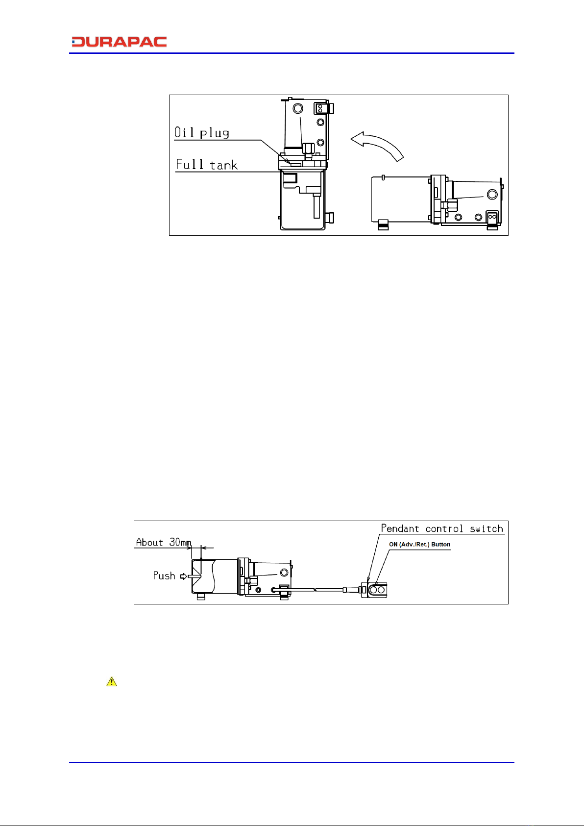
700 bar pressure on single acting cylinders and tools. The power unit has an internal ‘pop off’ valve
to indicate full pressure and remote pendant to actuate Advance/Retract functions. The power unit
is driven by a 0.35 kW, 230 Volt, 50/60 Hz single phase electric motor and may be used at any angle
due to the fully enclosed rubber lined reservoir. The power unit is lightweight and easily portable
using the shoulder strap and handle.
Special skill, knowledge and training may be required for a specific task and the product may not be
suitable for all jobs. The user must ultimately make the decision regarding suitability of the product
for any given task and assume the responsibility of safety for all in the work area. Contact a Durapac
representative if you are unsure of your power unit’s suitability for a particular application.
2.0 Receiving Instructions
It is recommended prior to use that an inspection be done by qualified personnel and that any
missing or damaged parts, decals, warning/safety labels or signs are replaced with Durapac
authorised replacement parts only. Any power unit that appears to be damaged in any way, is worn,
leaking or operates abnormally should be removed from service immediately until such time as
repairs can be made. Any power unit that has been or suspected to have been subject to a shock
load should be removed from service immediately until inspected by a Durapac authorised service
centre. Owners and operators of this equipment should be aware that the use and subsequent
repair of this equipment may require specialised training and knowledge.
3.0 Safety
Save these instructions. For your safety, read and understand the information contained within. The
owner and operator should have an understanding of this product and safe operating procedures
before attempting to use this product. Instructions and safety information should be conveyed in the
operator's native language before use of this product is authorised. Make certain that the operator
thoroughly understands the inherent dangers associated with the use and misuse of the product. If
any doubt exists as to the safe and proper use of this product as outlined in this factory authorised
manual, remove from service immediately.
DANGER:
To avoid personal injury keep hands and feet away from work area during operation
Do NOT handle pressurised hoses. Escaping oil under pressure can penetrate the skin
causing serious injury. If oil is injected under the skin, see a doctor immediately
Stay clear of loads supported by hydraulics. A cylinder, when used as a load lifting
device, should never be used as a load holding device. After the load has been raised
or lowered, it must always be supported mechanically

Instruction Manual
SPES3502AR Electric PU - V1.0 www.durapac.com Page 3 of 12
WARNING:
The system operating pressure must not exceed the pressure rating of the lowest
rated component in the system. Install pressure gauges in the system to monitor
operating pressure. It is your window to what is happening in the system
Always wear appropriate personal protective equipment (PPE) when operating
hydraulic equipment. The operator must take precaution against injury due to failure
of the tool or work piece(s)
Do NOT hold or stand directly in line with any hydraulic connections while pressurising
Do NOT attempt to disconnect hydraulic connections under pressure. Release all line
pressure before disconnecting hoses
All personnel must be clear before lowering load or depressurising the system
Do NOT attempt to lift a load weighing more than the capacity of the cylinder
IMPORTANT:
If at any stage, the safety related decals become hard to read, these must be replaced
Minimum age of the operator must be 18 years. The operator must have read and
understood all instructions, safety issues, cautions and warnings before starting to
operate the equipment. The operator is responsible for this activity towards other
persons
Do NOT lift hydraulic equipment by the hoses or couplers. Use the carrying handle or
other means of safe transport
Hydraulic equipment must only be serviced by a qualified hydraulic technician. For
repair service, contact the Durapac authorised service centre in your area. To protect
your warranty, use only high quality hydraulic oil
CAUTION:
KEEP HYDRAULIC EQUIPMENT AWAY FROM FLAMES AND HEAT. Hydraulic fluid can
ignite and burn. Excessive heat will soften packings and seals, resulting in fluid leaks.
Heat also weakens hose materials and packings. For optimum performance do not
expose equipment to temperatures of 55°C (131°F) or higher. Protect all equipment
from weld spatter
No alteration should be made to this device
3.1 Hydraulic Power Units
Do use a gauge or other load measuring instrument to verify load
Do NOT exceed the rated capacity of the power unit or any equipment in the system.
Burst hazard exists if connection pressure exceeds rated pressure
Do NOT operate the system with bent or damaged couplers or damaged threads
Do NOT subject the power unit and its components to shock loads
Use only Durapac approved accessories and components

Instruction Manual
SPES3502AR Electric PU - V1.0 www.durapac.com Page 4 of 12
Do NOT connect to an application which can return more oil to the reservoir than the
power unit reservoir can hold
Do NOT connect power unit to a hydraulic system that is powered by another pump
3.2 Hydraulic Hoses & Fluid Transmission Lines
Avoid short runs of straight line tubing. Straight line runs do not provide for expansion
and contraction due to pressure and/or temperature changes
Reduce stress in tube lines. Long tubing runs should be supported by brackets or clips.
Before operating the power unit, connections should be tightened securely and leak-
free. Over tightening can cause premature thread failure or high pressure fittings to
burst
Should a hydraulic hose ever rupture, burst or need to be disconnected, immediately
shut off the power unit and release all pressure. Never attempt to grasp a leaking
pressurised hose with your hands. The force of escaping hydraulic fluid can inflict
injury
Do NOT subject the hose to potential hazard such as fire, sharp objects, extreme heat
or cold or heavy impact
Do NOT allow the hose to kink, twist, curl, crush, cut or bend so tightly that the fluid
flow within the hose is blocked or reduced. Periodically inspect the hose for wear
Hose material and coupler seals must be compatible with the hydraulic fluid used.
Hoses also must not come in contact with corrosive materials such as battery acid,
creosote-impregnated objects and wet paint. Never paint a coupler or hose
FAILURE TO HEED THESE WARNINGS MAY RESULT IN PERSONAL INJURY AS WELL AS PROPERTY DAMAGE.
4.0 Installation
IMPORTANT: Always secure threaded port connections with high grade, non-hardening pipe
thread sealant. Teflon tape can be used if only one layer of tape is used and it is applied
carefully, two threads back, to prevent the tape from being introduced into hydraulic system,
which could cause jamming of precision-fit parts
To avoid power loss between the electrical outlet and the power unit motor, use the shortest
possible extension cord
4.1 Familiarise yourself with the specifications and illustrations in this owner’s manual. Know
your power unit, its limitations and how it operates before attempting to use. Refer to
the specification chart below or if in doubt, contact a Durapac representative.
10 bar 700 bar
SPES3502AR 0.35 230 50/60 4.5 1.6 700 2 0.2
Advance/Retract. Pop Off
valve indicates full pressure.
8.4
Maximum
Pressure
Rating
(bar)
Flow Rate
(Lpm)
Remote Pendant Function
2.4 mtr
Weight
(kg)
Model
Number
kW
Voltage
Hz
Amps
Usable Oil
Capacity
(L)

Instruction Manual
SPES3502AR Electric PU - V1.0 www.durapac.com Page 5 of 12
4.2 Make hydraulic connections –Clean all areas around the oil port of power unit and
cylinder. Clean all hose ends, couplers and union ends. Remove the manifold plug and
connect the 3/8”NPTF oil output port with a 700 bar hydraulic hose.
4.3 Check all system fittings and connections to be sure they are tight and leak free.
4.4 Check oil level in reservoir before operating power unit.
4.5 Power connection –Confirm the power unit’s voltage is the same as the voltage being
supplied by the site, the source is a stable supply and that the motor is correctly
grounded.
Ensure power is switched off prior to connection of hoses and equipment to prevent
early pressurisation
4.6 Remove air from the system –Air can accumulate in the hydraulic system during the
initial setup or after prolonged use, causing the cylinder to respond slowly or in an
unstable manner. Should removal of air from power unit be required, please follow the
steps in 6.2 –Bleeding Air from the System in the Maintenance Section.
5.0 Operation
IMPORTANT:
Always monitor pressure, load or position using suitable equipment. Pressure may be
monitored by means of an optional manifold and gauge. Correct application position
can only be determined by the operator of the equipment
Never set the relief valve to a higher pressure than the maximum rated pressure of the
power unit. Higher settings may result in equipment damage and/or personal injury
Do NOT remove the relief valve
Do NOT operate a power unit that is disconnected from the application. If operated in
this condition, the hose and connections will become pressurised. This increases the
chance of a burst hazard. Damage may also occur to the power unit and its
components
Although this power unit may be used at any angle, before use it must be secured or
supported to ensure that it does not slip and cause injury
This power unit is designed for indoor use, please protect from the elements if used
outside
The unlabelled second switch (below the ON switch) on the remote pendant is not
wired / does not work
5.1 Before Using the Power Unit
5.1.1 Check all system fittings and connections to be sure they are tight and leak free.
5.1.2 Check oil level in reservoir.

Instruction Manual
SPES3502AR Electric PU - V1.0 www.durapac.com Page 6 of 12
5.2 Power Unit Operation
5.2.1 Plug in power unit.
5.2.2 Press ON switch to run the motor and to Advance the cylinder.
5.2.3 Release ON switch to stop the motor and automatically Retract the cylinder.
Note –the cylinder retraction will occur after a slight pause because this power
unit is fitted with a pressure valve rather than a solenoid valve.
5.3 Relief Valve Adjustment
All power units contain a factory set internal relief valve to prevent over-pressurisation
of the system. A deck mounted adjustable pressure relief valve is also included and can
be set to lower working pressures (see Item 5, shown in Section 8.1 –High Level
Description of Parts).
Turn the adjusting screw a few turns (counter-clockwise) to decrease the pressure
setting to the desired level. Clockwise rotation of the adjusting screw will increase
pressure.
6.0 Maintenance
IMPORTANT:
Disconnect power supply before disassembly or repair
Check oil level regularly
Use only good quality hydraulic fluid. Do NOT use brake fluid, transmission fluid,
turbine oil, motor oil, alcohol, glycerine etc. Use of anything other than good quality
hydraulic oil will void warranty and damage the power unit, hose, and application. We
recommend Durapac Hydraulic Oil or equivalent
Equipment must only be serviced by a qualified hydraulic technician. For repair service,
contact your local Durapac authorised service centre
Damage to hydraulic hoses may not be detected during visual inspections. For this
reason, Durapac recommends that hydraulic hoses be replaced on a regular basis
Tighten connections as needed. Use non-hardening pipe thread compound when
servicing connections
Dirt, sand, etc. will quickly ruin any hydraulic system. Ensure that couplings are clean and
free of foreign matter. After each use, clean couplings and attach dust caps.
Maintenance is required when wear or leakage is noticed. Periodically inspect all
components to detect any problem that may require service and maintenance.
6.1 Adding Hydraulic Fluid
WARNING: Always add oil with cylinders fully retracted (or extended, if pull cylinders) or
the system will contain more oil than the reservoir can hold
6.1.1 Depressurise and disconnect hydraulic hose from application/cylinder.

Instruction Manual
SPES3502AR Electric PU - V1.0 www.durapac.com Page 7 of 12
6.1.2 With the power unit in its upright position (as shown below), remove the oil
plug located on the top plate of the reservoir.
Fig. 1 –Upright Position
6.1.3 Use a small funnel to fill with oil until reservoir is full.
6.1.4 Bleed air from system if necessary.
6.1.5 Wipe up any spilled fluid and reinstall the oil plug.
6.2 Bleeding Air from the System
6.2.1 Repeat Steps 6.1.1 to 6.1.3 (above), if required.
6.2.2 Ensure oil plug is closed.
6.2.3 Ensure the power unit is in its upright position (as shown above),invert
cylinder and place at a lower level than the power unit reservoir.
6.2.4 Using the pendant, extend and retract the cylinder several times without
putting a load on the system. Air should be released from the system.
6.2.5 If oil still cannot be delivered to develop pressure, place the power unit
horizontally (as shown below) and push the rubber lining through the 8mm
diameter hole on the tank cover end with a round ended rod (30mm or less),,
ensuring that damage is not done to the liner. Using the pendant, extend and
retract the cylinder several times.
Fig. 2 –Second Stage Air Removal
6.2.6 Recheck oil level after removing air.
6.3 Changing Hydraulic Fluid
For best results, change fluid once a year or every 300 hours of use
6.3.1 Repeat Steps 6.1.1 to 6.1.2 (above).
6.3.2 Pour used fluid into a sealable container.
6.3.3 Repeat Steps 6.1.3 to 6.1.5 (above).

Instruction Manual
SPES3502AR Electric PU - V1.0 www.durapac.com Page 8 of 12
6.3.4 Dispose of fluid in accordance with local regulations.
6.4 Replacing Carbon Brushes
Carbon brushes need to be replaced by a qualified technician
Replace when carbon brush has been worn down to 6mm in length (as shown below) or
every 150 hours of use. When worn, the motor will stop automatically
Fig. 3 –Carbon Brush Replacement
6.4.1 Remove rubber caps (x 2).
6.4.2 Use a screw driver to loosen and remove inside fitting screws so that carbon
brushes can be taken out.
6.4.3 Replace with new carbon brushes, fix the screws and rubber caps.
6.5 Storage
6.5.1 When not in use, depressurise and disconnect the power unit from the
application.
6.5.2 Wipe clean thoroughly and store in a clean, dry environment. Avoid
temperature extremes.
6.5.3 For transportation or long storage, replace the air vent plug with shipping
plug.
6.5.4 Shield power unit with a protective cover.

Instruction Manual
SPES3502AR Electric PU - V1.0 www.durapac.com Page 9 of 12
7.0 Troubleshooting
WARNING: Disconnect power supply before disassembly or repair
Problem
Cause
Solution
Motor will not start
Inadequate or faulty electrical
supply
Check the line voltage
Check the condition of the power
unit’s power cord
Check the condition of extension
cords
Check for tripped circuit breaker. Be
sure breaker is of adequate size
Contact a qualified electrician for
any necessary repairs
Carbon brush is worn
Refer to 6.4 –Replacing Carbon
Brushes
Noisy operation
Air trapped in system
Check all points where air may leak
into the system
Refer to 6.2 –Bleeding Air from the
System
Power unit reservoir too full
Drain fluid to correct level
Low fluid level in power unit
reservoir
Refer to 6.1 –Adding Hydraulic
Fluid
Fill and bleed the system
Power unit oil is over-
heating
Oil viscosity is too high
Refer to 6.3 –Changing Hydraulic
Fluid
Refill with a good quality hydraulic
oil
High pressure leakage on upper
pressure plate
Tighten plug
Low fluid level in power unit
reservoir
Refer to 6.1 –Adding Hydraulic
Fluid
Fill and bleed the system
Power unit runs but
will not pump oil
Power unit is not primed
Run power unit a few minutes
tipping from side to side
Externally adjustable relief valve
is not correctly set
Reset the relief valve to appropriate
level
Damaged o-ring
Send to a Durapac authorised
service centre for repair
Defective control valve
Send to a Durapac authorised
service centre for repair
Power unit does not
reach rated capacity
Low fluid level in reservoir
Secure load by other means
Depressurise power unit and hose,
remove application, then fill and
bleed the system
Leaking system components
Repair or replace as necessary
Poor performance
Fluid level in power unit is low
Secure load by other means
Depressurise power unit and hose,
remove application, then fill and
bleed the system

Instruction Manual
SPES3502AR Electric PU - V1.0 www.durapac.com Page 10 of 12
Problem
Cause
Solution
Application does not
extend, move or
respond to
pressurised fluid
Overload condition
Remedy overload condition
Loose couplers
Tighten couplers
Faulty couplers
Replace couplers
Malfunctioning power unit
Contact a Durapac authorised
service centre for repair
Application does not
fully extend (cylinder
or tools)
Reservoir overfilled
Secure load by other means
Depressurise power unit and hose,
remove application, then drain fluid
to proper level
Low fluid level in power unit
reservoir
Secure load by other means
Depressurise power unit and hose,
remove application, then fill and
bleed the system
Load above capacity of system
Use correct equipment
Application responds
slower than normal
Loose connection or coupler
Tighten couplers
Restricted hydraulic line or
fitting
Clean and replace if damaged
Power unit not operating
correctly
Check power unit’s operating
instructions
Repair or replace as necessary
Low fluid level in power unit
reservoir
Secure load by other means
Depressurise power unit and hose,
remove application, then fill and
bleed the system
Application responds
to pressurised fluid,
but system does not
maintain pressure
Leaky connection
Clean, reseal with thread sealant,
and tighten connection
Leaking cylinder seals
Replace worn seals. Look for
excessive contamination or wear.
Replace contaminated fluid
Power unit or valve not
operating correctly
Contact a Durapac authorised
service centre for repair
Overload condition
Remedy overload condition
Application does not
return fluid to power
unit (i.e. cylinder will
not retract)
Closed release valve
Secure load by other means
Open release valve
Loose couplers
Secure load by other means
Tighten couplers
Blocked hydraulic lines
Secure load by other means
Clean and flush lines
Weak or broken retraction
springs
Secure load by other means
Contact a Durapac authorised
service centre for repair
Internally damaged cylinder
Secure load by other means
Contact a Durapac authorised
service centre for repair
Power unit reservoir too full
Secure load by other means
Depressurise power unit and hose,
remove application, then drain fluid
to proper level

Instruction Manual
SPES3502AR Electric PU - V1.0 www.durapac.com Page 11 of 12
Item Description
1 Handle
2 Electric motor
3 Carbon brush
4 Tank cover
5 Relief valve
6 Power cable
7 Operation cord
8 Oil plug
9 Delivery port 3/8" NPTF
10 Pendant switch 2.4m
8.0 Parts Breakdown & List
8.1 High Level Description of Parts

Instruction Manual
SPES3502AR Electric PU - V1.0 www.durapac.com Page 12 of 12
9.0 Electric Schematic
10.0 Hydraulic Schematic
Table of contents
Other Durapac Portable Generator manuals

Durapac
Durapac 30 Series User manual

Durapac
Durapac 30 PEM3024 Series User manual

Durapac
Durapac DPA-16 User manual

Durapac
Durapac DPA-15D User manual

Durapac
Durapac DPA-38 User manual

Durapac
Durapac 15 Series User manual

Durapac
Durapac DPA-75 User manual

Durapac
Durapac 40 Series User manual

Durapac
Durapac PDM3054-Rail User manual

Durapac
Durapac 30 Series User manual