Durapac DPA-75 User manual

ABSOLUTE EQUIPMENT PTY LTD –2/186 Granite Street, GEEBUNG QLD 4034 –Australia
sales@absoluteequipment.com.au –Phone: +61 7 3865 4006 –Fax: +61 7 3102 6288
Maximum Operating Pressure –700 bar
Instruction Manual
Reciprocating Air Hydraulic Power Unit
Model –DPA-75

Instruction Manual
DPA-75 Air Hyd. Power Unit - V1.4 www.durapac.com Page 2 of 10
This is a safety alert symbol. It is used to alert you to potential personal injury hazards.
Obey all safety messages that follow this symbol to avoid injury or death
1.0 Product Information
DURAPAC –Reciprocating Air Hydraulic Power Units are engineered to meet Industrial Standards for
Performance and Safety. The DPA-75 model’s unique hydraulic circuit allows the quick displacement
of hydraulic fluid under no load conditions and easy pumping in loaded conditions. These air
actuated power units supply compressed hydraulic fluid to a compatible single-acting cylinder,
anywhere that 700 bar of fluid pressure is needed.
7.5 L usable oil reservoir
3 position treadle for adv/hold/retract functions
Dust cover protection for the release control valve
Release detent function enhances productivity
Convenient carry handle included
Recommended air pressure range 4-12 bar
Special skill, knowledge and training may be required for a specific task and the product may not be
suitable for all jobs. The user must ultimately make the decision regarding suitability of the product
for any given task and assume the responsibility of safety for all in the work area. Contact a Durapac
representative if you are unsure of your power unit’s suitability for a particular application.
2.0 Receiving Instructions
It is recommended prior to use that an inspection be done by qualified personnel and that any
missing or damaged parts, decals, warning/safety labels or signs are replaced with Durapac
authorised replacement parts only. Any power unit that appears to be damaged in any way, is worn,
leaking or operates abnormally should be removed from service immediately until such time as
repairs can be made. Any power unit that has been or suspected to have been subject to a shock
load should be removed from service immediately until inspected by a Durapac authorised service
centre. Owners and operators of this equipment should be aware that the use and subsequent
repair of this equipment may require specialised training and knowledge.
3.0 Safety
Save these instructions. For your safety, read and understand the information contained within. The
owner and operator should have an understanding of this product and safe operating procedures
before attempting to use this product. Instructions and safety information should be conveyed in the
operator's native language before use of this product is authorised. Make certain that the operator
thoroughly understands the inherent dangers associated with the use and misuse of the product. If
any doubt exists as to the safe and proper use of this product as outlined in this factory authorised
manual, remove from service immediately.
DANGER:
To avoid personal injury keep hands and feet away from work area during operation

Instruction Manual
DPA-75 Air Hyd. Power Unit - V1.4 www.durapac.com Page 3 of 10
Do NOT handle pressurized hoses. Escaping oil under pressure can penetrate the skin
causing serious injury. If oil is injected under the skin, see a doctor immediately
Stay clear of loads supported by hydraulics. A cylinder, when used as a load lifting
device, should never be used as a load holding device. After the load has been raised
or lowered, it must always be supported mechanically
WARNING:
The system operating pressure must not exceed the pressure rating of the lowest
rated component in the system. Install pressure gauges in the system to monitor
operating pressure. It is your window to what is happening in the system
Always wear appropriate personal protective equipment (PPE) when operating
hydraulic equipment. The operator must take precaution against injury due to failure
of the tool or work piece(s)
Do NOT hold or stand directly in line with any hydraulic connections while pressurising
Do NOT attempt to disconnect hydraulic connections under pressure. Release all line
pressure before disconnecting hoses
All personnel must be clear before lowering load or depressurising the system
Do NOT attempt to lift a load weighing more than the capacity of the cylinder
IMPORTANT:
If at any stage, the safety related decals become hard to read, these must be replaced
Minimum age of the operator must be 18 years. The operator must have read and
understood all instructions, safety issues, cautions and warnings before starting to
operate the equipment. The operator is responsible for this activity towards other
persons
Do NOT lift hydraulic equipment by the hoses or couplers. Use the carrying handle or
other means of safe transport
Hydraulic equipment must only be serviced by a qualified hydraulic technician. For
repair service, contact the Durapac authorised service centre in your area. To protect
your warranty, use only high quality hydraulic oil
CAUTION:
KEEP HYDRAULIC EQUIPMENT AWAY FROM FLAMES AND HEAT. Hydraulic fluid can
ignite and burn. Excessive heat will soften packings and seals, resulting in fluid leaks.
Heat also weakens hose materials and packings. For optimum performance do not
expose equipment to temperatures of 65°C (150°F) or higher. Protect all equipment
from weld spatter
No alteration should be made to this device
3.1 Hydraulic Power Units
Do use a gauge or other load measuring instrument to verify load
Do NOT exceed the rated capacity of the power unit or any equipment in the
system. Burst hazard exists if connection pressure exceeds rated pressure

Instruction Manual
DPA-75 Air Hyd. Power Unit - V1.4 www.durapac.com Page 4 of 10
Do NOT operate the system with bent or damaged couplers or damaged threads
Do NOT subject the power unit and its components to shock loads
Use only Durapac approved accessories and components
Do NOT connect to an application which can return more oil to the reservoir than
the power unit reservoir can hold
Do NOT connect the power unit to a hydraulic system that is powered by another
pump
3.2 Hydraulic Hoses & Fluid Transmission Lines
Avoid short runs of straight line tubing. Straight line runs do not provide for
expansion and contraction due to pressure and/or temperature changes
Reduce stress in tube lines. Long tubing runs should be supported by brackets or
clips. Before operating the power unit, connections should be tightened securely
and leak-free. Over tightening can cause premature thread failure or high pressure
fittings to burst
Should a hydraulic hose ever rupture, burst or need to be disconnected,
immediately shut off the power unit and release all pressure. Never attempt to
grasp a leaking pressurised hose with your hands. The force of escaping hydraulic
fluid can inflict injury
Do NOT subject the hose to potential hazard such as fire, sharp objects, extreme
heat or cold or heavy impact
Do NOT allow the hose to kink, twist, curl, crush, cut or bend so tightly that the fluid
flow within the hose is blocked or reduced. Periodically inspect the hose for wear
Hose material and coupler seals must be compatible with the hydraulic fluid used.
Hoses also must not come in contact with corrosive materials such as battery acid,
creosote-impregnated objects and wet paint. Never paint a coupler or hose
FAILURE TO HEED THESE WARNINGS MAY RESULT IN PERSONAL INJURY AS WELL AS PROPERTY DAMAGE.
4.0 Installation
IMPORTANT:
Always secure threaded port connections with high grade, non-hardening pipe thread
sealant. Teflon tape can be used if only one layer of tape is used and it is applied
carefully, two threads back, to prevent the tape from being introduced into hydraulic
system, which could cause jamming of precision-fit parts
To extend the life of your power unit, the air compressor should have a filter, regulator
and lubricator system that will provide clean, lubricated air to the power unit. Contact
your Durapac representative for the necessary accessories
4.1 Familiarise yourself with the specifications and illustrations in this owner’s manual.
Know your power unit, its limitations and how it operates before attempting to use.
Refer to the specification chart below or if in doubt, contact a Durapac representative.

Instruction Manual
DPA-75 Air Hyd. Power Unit - V1.4 www.durapac.com Page 5 of 10
4.2 Replace shipping plug (red) with air vent plug (black) before use.
4.3 Air Connection - Remove plastic cap from the air inlet port on the end of the power
unit, connect suitable air supply to air input port. Air input port is designed to fit the
popular 1/4" NPT air nipple (not included). Ensure that your air source can dedicate 7.8
cfm @ 4-12 bar/60-175 psi to each power unit being operated.
Figure 1 –DPA-38 used for illustration purposes
4.4 Remove air from the power unit –Air can accumulate in the hydraulic system during
the initial setup or after prolonged use, causing the cylinder to respond slowly or in an
unstable manner. Should removal of air from power unit be required, please follow the
steps in 6.2 –Bleeding Air from the System in the Maintenance Section.
4.5 Check all system fittings and connections to be sure they are tight and leak free.
4.6 Check oil level in reservoir before operating power unit.
5.0 Operation
IMPORTANT:
Always monitor pressure, load or position using suitable equipment. Pressure may be
monitored by means of an optional manifold and gauge. Load may be monitored by
means of a load cell and digital indicator. Correct application position can only be
determined by the operator of the equipment
Do NOT operate a power unit that is disconnected from the application. If operated in
this condition, the hose and connections will become pressurised. This increases the
chance of a burst hazard. Damage may also occur to the power unit and its
components
5.1 To extend the cylinder, depress on the foot pedal marked "Pump" (horizontal portion)
until desired pressure, load or position is reached.
No load Load
DPA-75 S/A 3/8"-NPTF 7,550 700 1,075 150 4-12 17.4
Air Pressure
Range (bar)
Weight
(kg)
Model
Number
Used
with
Cylinder
Oil Port
Thread
Usable Oil
Capacity
(cc)
Pressure
Rating
(bar)
Output Flow Rate
(cm3/min)

Instruction Manual
DPA-75 Air Hyd. Power Unit - V1.4 www.durapac.com Page 6 of 10
5.2 To hold the cylinder in position, release the foot pedal to deactivate the power unit.
5.3 To retract the cylinder, depress the release valve by stepping on the foot pedal marked
"Release" (raised, stirrup shaped portion).
6.0 Maintenance
IMPORTANT:
Check oil level regularly
Use only good quality hydraulic fluid. Do NOT use brake fluid, transmission fluid,
turbine oil, motor oil, alcohol, glycerine etc. Use of anything other than good quality
hydraulic oil will void warranty and damage the power unit, hose, and application. We
recommend Durapac Hydraulic Oil or equivalent
Equipment must only be serviced by a qualified hydraulic technician. For repair service,
contact your local Durapac authorised service centre
Damage to hydraulic hoses may not be detected during visual inspections. For this
reason, Durapac recommends that hydraulic hoses be replaced on a regular basis
Tighten connections as needed. Use non-hardening pipe thread compound when
servicing connections
Dirt, sand, etc. will quickly ruin any hydraulic system. Ensure that couplings are clean and free of
foreign matter. After each use, clean couplings and attach dust caps.
Maintenance is required when wear or leakage is noticed. Periodically inspect all components to
detect any problem that may require service and maintenance.
6.1 Adding Hydraulic Fluid
WARNING: Always add oil with cylinders fully retracted (or extended, if pull cylinders) or
the system will contain more oil than the reservoir can hold
6.1.1 Depressurise and disconnect hydraulic hose from application/cylinder.
6.1.2 With the power unit in its upright, horizontal position, remove the air vent plug
located on the top plate of the reservoir.
6.1.3 Use a small funnel to fill the reservoir to within 19mm (3/4") of the opening.
6.1.4 Bleed air from system if necessary.
6.1.5 Wipe up any spilled fluid and reinstall the air vent plug/reservoir cap.
6.2 Bleeding Air from the System
6.2.1 Repeat Steps 6.1.1 to 6.1.3 (above), if required.
6.2.2 Invert cylinder and place at a lower level than the power unit reservoir.
6.2.3 Extend and retract the cylinder several times without putting a load on the
system. Air will be released into the power unit reservoir.
6.2.4 Recheck oil level after removing air.

Instruction Manual
DPA-75 Air Hyd. Power Unit - V1.4 www.durapac.com Page 7 of 10
6.3 Changing Hydraulic Fluid
For best results, change fluid once a year or every 300 hours of use
6.3.1 Repeat Steps 6.1.1 to 6.1.2 (above).
6.3.2 Pour used fluid into a sealable container.
6.3.3 Repeat Steps 6.1.3 to 6.1.5 (above).
6.3.4 Dispose of fluid in accordance with local regulations.
6.4 Lubrication
When power unit is operated on a daily basis, it is recommended that an inline oiler
and air dryer is installed and SAE grade oil (5W to 30W) is used.
6.5 Storage
6.5.1 When not in use, depressurise and disconnect the hydraulic power unit from
the application.
6.5.2 Wipe clean thoroughly and store in a clean, dry environment. Avoid
temperature extremes.
6.5.3 For transportation or long storage, replace the air vent plug with shipping plug.
6.5.4 Shield power unit with a protective cover.

Instruction Manual
DPA-75 Air Hyd. Power Unit - V1.4 www.durapac.com Page 8 of 10
7.0 Troubleshooting
Problem
Cause
Solution
Application does not extend,
move or respond to
pressurised fluid
Overload condition
Remedy overload condition
Loose couplers
Tighten couplers
Faulty couplers
Replace couplers
Malfunctioning power unit
Contact a Durapac
authorised service centre
Repair or replace as
necessary
Inadequate air supply
Ensure air source can
dedicate 7.8 cfm @ 4-12
bar/60-175 psi
Application responds to
pressurised fluid, but system
does not maintain pressure
Overload condition
Remedy overload condition
Malfunctioning power unit or
valve
Contact a Durapac
authorised service centre
Repair or replace as
necessary
Leaking application/connection
Replace
application/connection
Application responds slower
than normal
Loose connection or coupler
Tighten connection or
coupler
Restricted hydraulic line or
fitting
Clean and replace if
damaged
Leaking application/connection
Replace
application/connection
Application does not return
fluid to power unit (i.e.
cylinder will not retract)
Malfunctioning coupler/
damaged application
Secure load by other
means
Depressurise power unit
and hose
Remove coupler and/or
application
Repair or replace as
necessary
Application does not fully
extend (cylinder or spreader)
Overfilled reservoir
Secure load by other
means
Depressurise power unit
and hose
Remove application
Drain fluid to proper level
Low fluid level in power unit
Secure load by other
means
Depressurise power unit
and hose
Remove application
Fill fluid to proper level
Poor performance
Low fluid level in power unit
Ensure proper fluid level

Instruction Manual
DPA-75 Air Hyd. Power Unit - V1.4 www.durapac.com Page 9 of 10
8.0 Parts Breakdown
Note: Not all components of the power unit are replacement items, but are illustrated as a
convenient reference of location and position in the assembly sequence.

Instruction Manual
DPA-75 Air Hyd. Power Unit - V1.4 www.durapac.com Page 10 of 10
Items marked with a * are contained within a standard Repair Kit.
Serial, model and part numbers need to be quoted when ordering parts.
9.0 Parts List
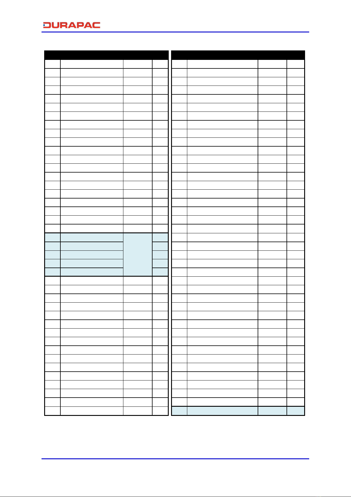
Item Description Part No. Qty Item Description Part No. Qty
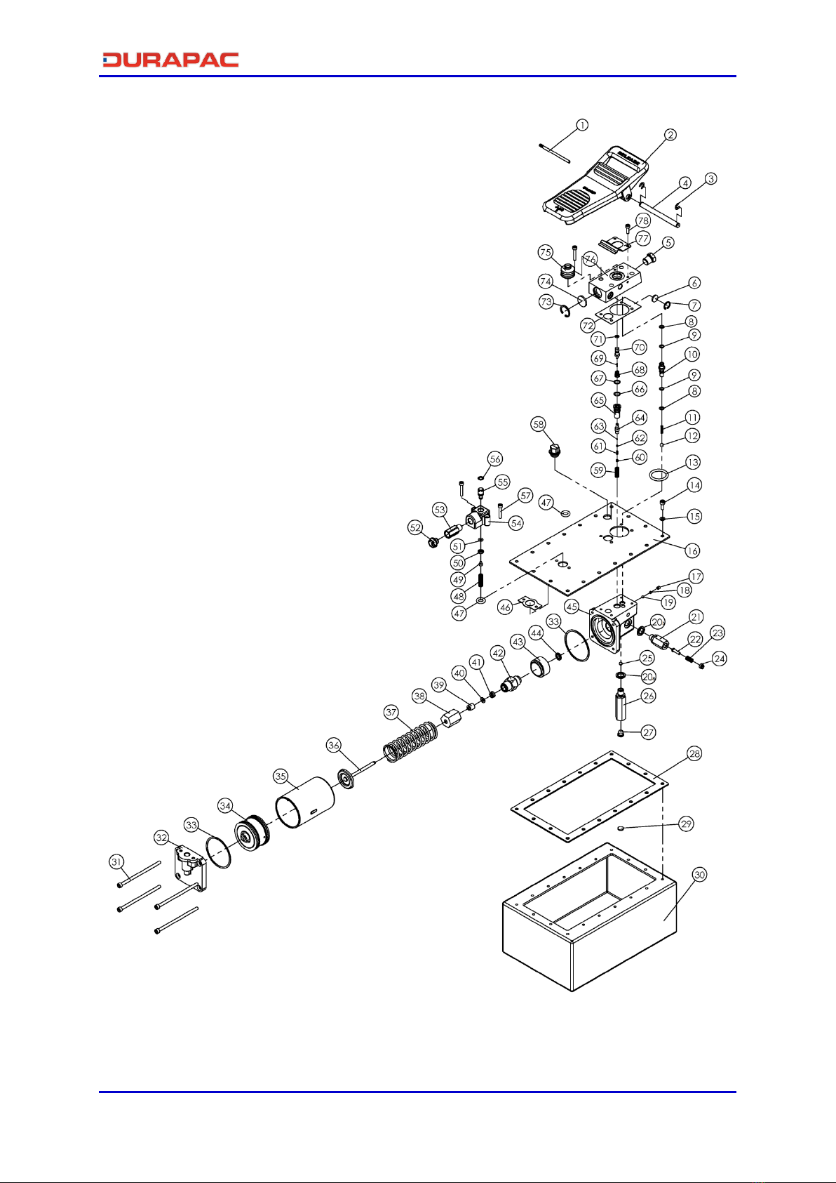
1 Steel bar ZBN1016 1 41 U-cup* ZBN1062 1
2 Foot pedal ZBN1017 1 42 Pump ZBN1095 1
3 E-clip* ZBN1034 2 43 Washer ZBN1063 1
4 Foot pedal bar ZBN1035 1 44 Special washer ZBN1064 1
5 Nut ZBN1036 1 45 Base ZBN1065 1
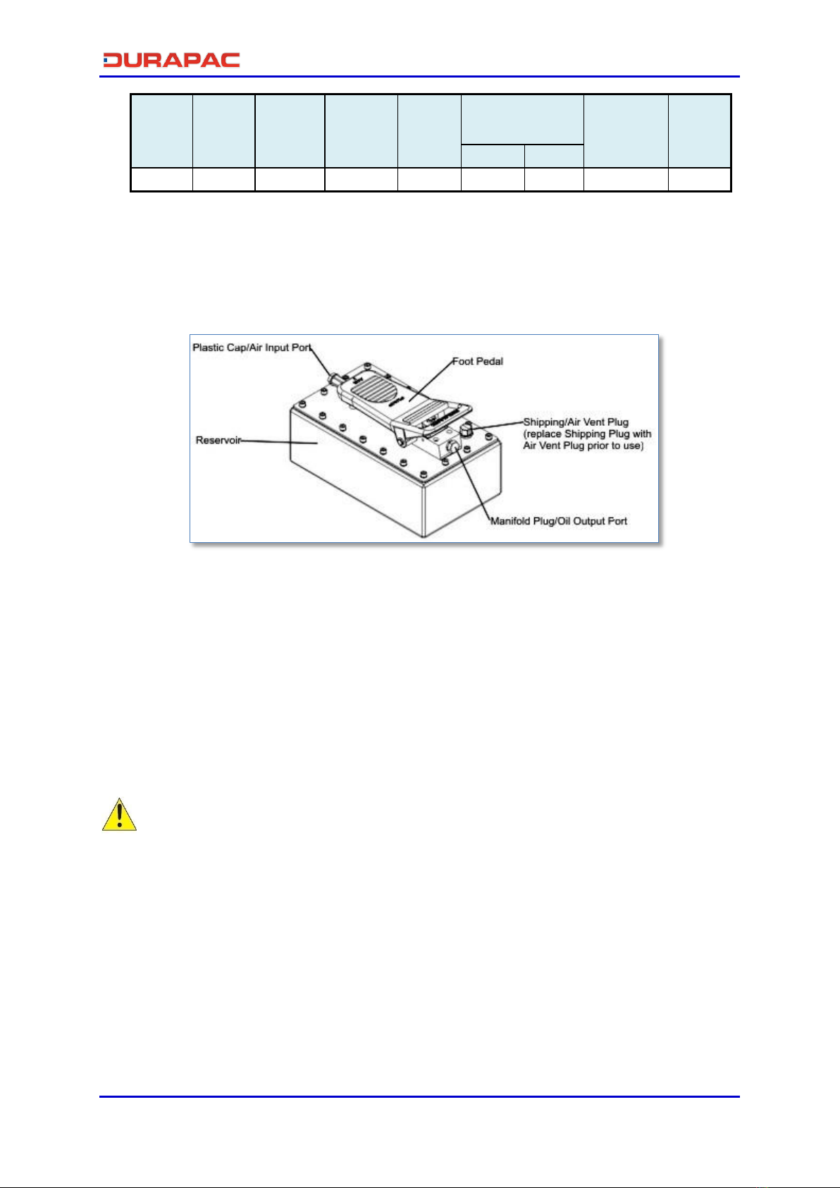
6 Silencer ZBN1013 1 46 Pad B ZBN1012 1
7 C-clip ZBN1003 1 47 O-ring ZBN1000 2
8 O-ring* ZBN1037 2 48 Compressing spring ZBN1066 1
9 Back-up ring* ZBN1038 2 49 Screw ZBN1067 1
10 Oil outlet valve ZBN1039 1 50 Air entrance cap ZBN1068 1
11 Compressing spring ZBN1040 1 51 O-ring ZBN1069 1
12 Steel ball ZBN1041 1 52 Plastic cover ZBN1007 1
13 O-ring ZBN1001 1 53 Connector ZBN1156 1
14 Screw ZBN1161 18 54 Air entrance base ZBN1070 1
15 Washer ZBN1091 18 55 Air entrance valve ZBN1014 1
16 Oil tank cover ZBN1162 1 56 O-ring ZBN1071 1
17 Screw ZBN1043 1 57 Screw ZBN1072 6
18 Steel ball block ZBN1044 1 58a Shipping plug (red) ZBN1073 1
19 Steel ball ZBN1045 1 58b Air vent plug (black) ZBN1167 1
20a Special washer* ZBN1046 1 59 Compressing spring ZBN1074 1
20b Special washer* 1 60 Screw ZBN1075 1
21 High pressure valve 1 61 Compressing spring* ZBN1076 1
22 Nail 1 62 Steel ball block ZBN1077 1
23 Compressing spring 1 63 Steel ball ZBN1078 1
24 Pressure adjust. nut 1 64 Release valve ZBN1079 1
25 Steel ball ZBN1051 1 65 Release base ZBN1080 1
26 Oil entrance valve ZBN1163 1 66 O-ring* ZBN1081 1
27 Filter ZBN1002 1 67 Back-up ring* ZBN1082 1
28 Pad ZBN1164 1 68 Bevel compress. Spring ZBN1083 1
29 Magnet ZBN1092 1 69 Release nail ZBN1084 1
30 Reservoir ZBN1166 1 70 Release bar ZBN1085 1
31 Screw ZBN1053 4 71 O-ring* ZBN1086 1
32 Motor cover ZBN1054 1 72 Pad A* ZBN1087 1
33 Cylinder washer ZBN1055 2 73 C-clip ZBN1004 1
34 Air piston assembly ZBN1005 1 74 Silencer ZBN1006 1
35 Cylinder ZBN1056 1 75 Dust cap ZBN1018 1
36 Piston assembly ZBN1093 1 76 Oil outlet base ZBN1088 1
37 Compressing spring ZBN1058 1 77 Leaf spring ZBN1015 1
38 Piston cover ZBN1059 1 78 Screw ZBN1042 2
39 Bush ZBN1094 1 Repair kit ZBN1010 1
40 Back-up ring ZBN1061 1 High Pressure Valve Assy ZBN1124 1
High
Pressure
Valve
Assy
Table of contents
Other Durapac Portable Generator manuals

Durapac
Durapac 30 Series User manual

Durapac
Durapac DPA-16 User manual

Durapac
Durapac DPA-38D User manual

Durapac
Durapac SPES3502AR User manual

Durapac
Durapac DPA-18 User manual

Durapac
Durapac DPA-15D User manual

Durapac
Durapac DPR-223S User manual

Durapac
Durapac PEM4024 User manual

Durapac
Durapac PES1513 User manual

Durapac
Durapac 30 PEM3024 Series User manual