dymax BlueWave 200 User manual

BlueWave®200 Version 3.0 User Guide
UV Light-Curing Spot Lamp System
■Instructions for Safe Use
■Setup and Operation
■Maintenance
■Ordering Spare Parts and Accessories

2
Dymax BlueWave® 200 Version 3.0 User Guide
About Dymax
UV/Visible light-curable adhesives. Systems for light curing, fluid dispensing, and fluid packaging.
Dymax manufactures industrial adhesives, light-curable adhesives, epoxy resins, cyanoacrylates, and activator-cured adhesives.
We also manufacture a complete line of manual fluid dispensing systems, automatic fluid dispensing systems, and light-curing systems.
Light-curing systems include LED light sources, spot, flood, and conveyor systems designed for compatibility and high performance
with Dymax adhesives.
Dymax adhesives and light-curing systems optimize the speed of automated assembly, allow for 100% in-line inspection, and increase
throughput. System designs enable stand-alone configuration or integration into your existing assembly line.
Please note that most dispensing and curing system applications are unique. Dymax does not warrant the fitness of the product for the
intended application. Any warranty applicable to the product, its application, and use is strictly limited to that contained in the Dymax
standard Conditions of Sale. Dymax recommends that any intended application be evaluated and tested by the user to ensure that desired
performance criteria are satisfied. Dymax is willing to assist users in their performance testing and evaluation by offering equipment trial
rental and leasing programs to assist in such testing and evaluations. Data sheets are available for valve controllers or pressure pots upon
request.

3
Dymax BlueWave® 200 Version 3.0 User Guide
Contents
Introduction.................................................................................................................................................... 5
Introduction to the User Guide ....................................................................................................................................... 5
Where to Get Help .......................................................................................................................................................... 5
Safety.............................................................................................................................................................. 5
General Safety Considerations ........................................................................................................................................ 5
Specific Safety Considerations......................................................................................................................................... 5
Dymax UV Light-Curing System Safety Considerations ................................................................................................... 6
Product Overview ........................................................................................................................................... 8
Description of the BlueWave 200.................................................................................................................................... 8
Unpacking the BlueWave 200 ......................................................................................................................... 9
Unpacking and Inspecting Your Shipment....................................................................................................................... 9
Parts Included with the BlueWave 200 Spot Lamp.......................................................................................................... 9
Setting Up the BlueWave 200 ....................................................................................................................... 10
Becoming Familiar with the Controls ............................................................................................................ 11
Turning the BlueWave 200 On ...................................................................................................................... 12
Setting an Operating Mode........................................................................................................................... 13
Introduction to Operating Modes ................................................................................................................................. 13
Choosing an Operating Mode........................................................................................................................................ 13
Operating in Manual Mode........................................................................................................................... 17
Manual Mode Description............................................................................................................................................. 17
Procedure ...................................................................................................................................................................... 17
Operating in Timer Mode.............................................................................................................................. 18
Timer Mode Description................................................................................................................................................ 18
Procedure to Adjust Timer ............................................................................................................................................ 18
Operating in PLC Mode ................................................................................................................................. 20
PLC Mode Description ................................................................................................................................................... 20
Start-Up Screen for PLC Mode....................................................................................................................................... 20
Using the PLC Switch ..................................................................................................................................................... 21
Wiring the PLC Interface................................................................................................................................................ 23
PLC Front Panel Emergency Stop................................................................................................................................... 26
Troubleshooting the PLC Interface ................................................................................................................................ 26
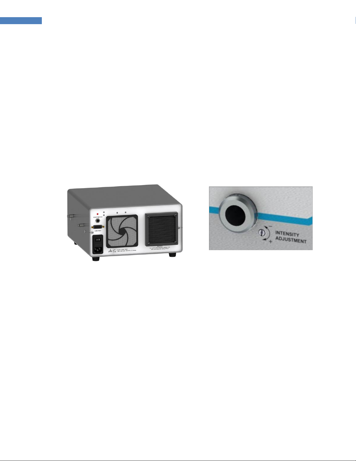
Setting the Intensity...................................................................................................................................... 27
Setting Up the Curing Process ....................................................................................................................... 27
Methods ........................................................................................................................................................................ 27
Maintaining Process Control ......................................................................................................................................... 28
Maintaining the BlueWave 200..................................................................................................................... 28
Bulb Replacement Warning........................................................................................................................................... 28
Bulb Replacement Procedure........................................................................................................................................ 28
Lightguide...................................................................................................................................................................... 30
Fan Filter........................................................................................................................................................................ 30
Fuse Replacement ......................................................................................................................................................... 30
System Cleaning ............................................................................................................................................................ 31

4
Dymax BlueWave® 200 Version 3.0 User Guide
Solving Problems .......................................................................................................................................... 31
Troubleshooting ............................................................................................................................................................ 31
Frequently Asked Questions.......................................................................................................................................... 32
Diagnostic Display ......................................................................................................................................................... 33
Spare Parts and Accessories.......................................................................................................................... 34
Spare/Replacement Parts.............................................................................................................................................. 34
Options/Accessories...................................................................................................................................................... 34
Specifications................................................................................................................................................ 35
System Specifications .................................................................................................................................................... 35
Bulb Spectral Output ..................................................................................................................................................... 36
Definition of Terms ....................................................................................................................................... 37
Warranty ...................................................................................................................................................... 38
Replacement Bulb Warranty ......................................................................................................................................... 38
Index............................................................................................................................................................. 39

5
Dymax BlueWave® 200 Version 3.0 User Guide
Introduction
Introduction to the User Guide
This guide describes how to assemble, use, and maintain the BlueWave® 200 Rev. 3.0 light-curing spot lamp
system safely and efficiently. Dymax prepared this user guide for experienced process engineers, technicians,
and manufacturing personnel. If you are new to UV light-curing equipment and do not understand the
instructions, contact Dymax Application Engineering to answer your questions before using the equipment.
Where to Get Help
Dymax Customer Support and Application Engineering teams are available in the United States, Monday
through Friday, from 8:00 a.m. to 5:30 p.m. Eastern Standard Time. You can also email Dymax at
[email protected]. Contact information for additional Dymax locations can be found on the back cover of this
user guide.
Additional resources are available to ensure a trouble-free experience with our products:
Detailed product information on www.dymax.com
Dymax adhesive Product Data Sheets (PDS) on our website
Material Safety Data Sheets (MSDS) provided with shipments of Dymax adhesives
Safety
WARNING! If you use this UV light-curing system without first reading and understanding
the information in this user guide, injury can result from exposure to high-intensity UV light. To
reduce the risk of injury, read and ensure you understand the information in this user guide
before assembling and operating the Dymax BlueWave spot lamp.
To use this system safely, it must be set up and operated in accordance with the instructions
given by Dymax. Using the system in any other manner will impair the protection of the system.
Dymax assumes no liability for any changes that may impair the protection of the system.
General Safety Considerations
All users of Dymax light-curing systems should read and understand this user guide before assembling and
using the system.
To learn about the safe handling and use of light-curable formulations, obtain and read the MSDS for each
product. Dymax includes an MSDS with each adhesive sold. In addition, fluid product MSDS can be requested
on our website.
Specific Safety Considerations
The BlueWave 200 is designed to maximize operator safety and minimize exposure to UV light. To use the
BlueWave 200 safely, it must be set up and operated in accordance with the instructions in this user guide.
Please also read and understand the safety considerations unique to UV light-curing systems.

6
Dymax BlueWave® 200 Version 3.0 User Guide
CAUTIONS & WARNINGS! To prevent eye injury from ultra-violet energy, always wear
UV-blocking protective goggles or a face shield when working with or near the BlueWave 200.
Long-sleeved shirts or a lab coat are also recommended to protect the arms and use of UV-
opaque gloves will protect the hands.
With the internal filter installed, the BlueWave 200 emits UVA and visible light. Never look
directly at the light source while the unit is on.
Always observe safety requirements.
There is risk of electrical shock if cover is removed.
Cover is warm to the touch when the system is in operation.
Dymax UV Light-Curing System Safety Considerations
Operators must understand these four concepts to use the UV light-curing system safely: UV exposure, high-
temperature surfaces, ozone, and bright, visible light. Each is described below.
UV Exposure
Standard Dymax UV light-curing systems and bulbs have been designed to primarily emit UVA light (Figure 1).
UVA light is generally considered the safest of the three UV ranges: UVA, UVB, and UVC. Although OSHA does
not currently regulate ultraviolet light exposure in the workplace, the American Conference of Governmental
Industrial Hygienists (ACGIH) does recommend Threshold Limit Values (TLVs) for ultraviolet light. The strictest
interpretation of the TLV (over the UVA range) for workers’ eyes and skin is 1 mW/cm2(intensity), continuous
exposure. Unless workers are placing bare hands into the curing area, it is unusual to exceed these limits. To
put the 1 mW/cm2limit into perspective, cloudless summer days in Connecticut regularly exceed 3 mW/cm2of
UVA light and also include the more dangerous UVB light (primarily responsible for sun tans, sun burns, and
skin cancer) as well.
Figure 1. UV Spectrum
The human eye cannot detect “pure” UV light, only visible light. A radiometer should be used to measure
stray UV light to confirm the safety of a UV light-curing process. A workstation that exposes an operator to
more than 1 mW/cm2of UVA continuously should be redesigned.

7
Dymax BlueWave® 200 Version 3.0 User Guide
UV light-curing of adhesives can be a regulatory compliant, “worker-friendly” manufacturing process when the
proper safety equipment and operator training is utilized. There are two ways to protect operators from UV
exposure: shield the operator and/or shield the source.
Shield the Operator
UV-Blocking Eye Protection - UV-blocking eye protection is recommended when operating UV light-curing
systems. Both clear and tinted UV-blocking eye protection is available from Dymax.
UV-Blocking Skin Protection -Where the potential exists for UV exposure upon skin, opaque, UV-blocking
clothing, gloves, and full-face shields are recommended.
Shield the Source of UV
Any substrate that blocks UV light can be used as a shield to protect workers from stray UV light. The following
materials can be used to create simple shielding structures or blind corners:
Sheet Metal -Aluminum, steel, stainless steel, etc. Sheet metal should be coated black or black anodized to
minimize reflection of UV and visible light toward operators.
Rigid Plastic Film -Transparent or translucent/UV-blocking plastics (typically polycarbonate or acrylic) are
commonly used to create shielding where some level of transparency is also desired. These rigid plastic films
are water-clear or tinted.
Flexible Film -UV-blocking, flexible urethane films can be used to quickly create workstation shielding. This
UV-blocking, flexible urethane film is available from Dymax, call for assistance.
High-Temperature Surfaces
Surfaces exposed to high-intensity curing lights will rise in temperature. The intensity, distance, exposure
time, cooling fans, and the type/color of the surface can all affect the actual surface temperature. In some
cases, exposed surfaces can reach temperatures capable of producing a burn or causing damage to a
substrate. In these cases, care must be taken to ensure a more moderate surface temperature or appropriate
protection and training for operators.
Ozone
Standard Dymax bulbs (UVA type) generate an insignificant amount of UVC and therefore essentially no
ozone. Some UV light-curing systems, like those used to cure UV inks, emit primarily “shortwave” (UVB and
UVC) energy. Upon exposure to UVC light (specifically <240 nm), oxygen molecules (O2) split into oxygen
atoms (O) and recombine with O2to create ozone O3. The current, long-term ozone concentration limit
recommended by ACGIH, NIOSH, and OSHA is 0.1 ppm (0.2 mg/m3).
Bright, Visible Light
The bright, visible light emitted by some UV light-curing systems can be objectionable to some workers and
can cause eyestrain. Tinted eye protection and/or opaque/tinted shielding can be utilized to address this
concern.

8
Dymax BlueWave® 200 Version 3.0 User Guide
Summary
UV light sources can be more “worker friendly” than many commonly accepted industrial processes, provided
the potential concerns are addressed. Contact your Dymax representative for information regarding the
proper use of Dymax UV light-curing systems.
Product Overview
Description of the BlueWave 200
The BlueWave 200 is a high-intensity, UV light-curing spot lamp system used for small-area curing of
adhesives, coatings, and potting materials. It emits up to an 8-mm diameter spot of UV light from a liquid
lightguide (sold separately). The lightguide can be hand-held for complete mobility or clamped into position
on assembly equipment or workstations for repetitive operations.
The system consists of an anodized aluminum housing containing an electronic power supply, circuit
protection, bulb/reflector assembly, internal light filter for extended lightguide life, thermostatically-
controlled cooling fan, and LCD display. The shutter can be controlled through externally-supplied signals in
PLC Mode, with a foot pedal or button press in Manual Mode, or through a built-in timer triggered by a foot
pedal or button press in Timer Mode.
The power supply operates on line voltages between 100 and 240 VAC, and frequency between 50 and 60 Hz.
It is auto-ranging and is specially designed to provide proper rated voltage and current to the 200-Watt lamp.
A cooling fan with a control loop is provided to keep the lamp housing and internal components of the power
supply at the optimum operating temperature. The cooling fan must not be covered or otherwise blocked.
Ideal operation of this equipment suggests at least 12" (305 mm) of clearance behind the system for proper
ventilation. Confirm that the intake fan is not feeding from the exhaust of other equipment.
The UV source is a 200-Watt, medium-pressure arc metal-halide bulb mounted in a reflector and focused to
provide optimum light output. The BlueWave 200 is rated for continuous operation. The bulbs used to power
all high-intensity UV light-curing spot lamps degrade with use. Intensity, therefore, decreases as the bulb
ages. Using the system’s intensity control feature, users can eliminate this variation by manually increasing
intensity to offset this degradation. During operation a user can adjust the output intensity using a tool or
removable knob. If the bulb extinguishes due to a momentary power failure, the BlueWave 200 must be
turned off, allowed to cool, and then restarted to re-ignite the bulb. The LCD display will indicate when the
bulb must be replaced.
A thermal shutdown sensor is provided for internal temperature control of the BlueWave 200. A cover switch
and lightguide status switch increase the safety of the unit. If any of these sensors prevent the system from
operating as intended, specific warnings appear on the LCD display.
When the BlueWave 200 is operating in PLC Mode, the LCD display shows the state of the signals which
control the BlueWave 200 to help set up and verify correct operation of the system.

9
Dymax BlueWave® 200 Version 3.0 User Guide
Unpacking the BlueWave 200
Unpacking and Inspecting Your Shipment
When your BlueWave 200 arrives, inspect the boxes for damage and notify the shipper of box damage
immediately.
Open each box and check for equipment damage. If parts are damaged, notify the shipper and submit a claim
for the damaged parts. Contact Dymax so that new parts can be shipped to you immediately.
Check that the parts included in your order match those listed below. If parts are missing, contact your local
Dymax representative or Dymax Customer Support to resolve the problem.
NOTE: Lamps are shipped with the bulb/reflector installed.
Figure 2. BlueWave 200 Rev 3.0 Components
Parts Included with the BlueWave 200 Spot Lamp
■BlueWave 200 Rev. 3.0 Spot Lamp (1)
■Power Cord (2)
41015 –North American Version with 115V Power Cord
41014 –Asian Version with Type G Plug
41013 –No Power Cord (NOTE: For European customers, the appropriate power cord will be added)
■Foot Pedal (3)
■Protective Goggles (4)
■Hex Key (5)
■Screwdriver (6)
■Intensity Adjustment Knob and Screw (7)
■BlueWave 200 User Guide (8)
1
2
3
4
5
6
7
8

10
Dymax BlueWave® 200 Version 3.0 User Guide
Setting Up the BlueWave 200
1. Connect the Power Cord to the Power Receptacle on the rear of the BlueWave 200. Plug the Power Cord
into a grounded wall outlet.
2. If you will be using a Foot Pedal, connect the Foot Pedal to the Foot Pedal Connection (Figure 3) on the
rear of the BlueWave 200. A ground stud is also provided on the back of the BlueWave 200 if additional
grounding is desired.
3. Remove the protective cover from the BlueWave 200’s Lightguide Mount (Figure 4).
NOTE: Always have a Lightguide or the protective cap engaged in the Lightguide Mount. UV light can
escape when the Shutter is activated.
Figure 3. Cable Connections,
BlueWave 200 Rev 3.0 Rear Panel
Figure 4. Lightguide Mount,
Protective Cover Removed
4. Remove the Protective End Caps from the Lightguide. Visually inspect the two ends of the Lightguide to
verify that no foreign material is present. The ends of a Dymax liquid-filled Lightguide can be cleaned with
isopropyl alcohol as required to remove foreign material and deposition from outgassing.
5. Insert the large end of the Lightguide into the Lightguide Mount until it snaps into place (Figure 5). A
Lightguide Seated Indicator Icon will illuminate when the Lightguide is properly installed and the
BlueWave 200 is turned on.
WARNING! Engage the Lightguide in the Bezel before the light is turned on, and remove the
Lightguide from the Bezel only after the light is turned off to avoid the possibility of exposure to the light.
Lightly tighten the setscrew for safety.
6. Fasten the Lightguide into place by lightly tightening the Setscrew located on the Lightguide Mount
(Figure 6). A Hex Wrench is provided with the system for this purpose. The Setscrew should be tightened
gently to prevent damage to the Lightguide.
IMPORTANT: To ensure proper operation of the Shutter, be sure to completely insert the Lightguide
into the Lightguide Mount prior to tightening the Setscrew. Be sure to lightly tighten the Setscrew to
ensure the Lightguide remains in place during use.

11
Dymax BlueWave® 200 Version 3.0 User Guide
NOTE: Multi-Leg Lightguides should be balanced by rotating the Lightguide to obtain the desired UV
intensity of each leg before lightly tightening the Setscrew.
Figure 5. Insert Lightguide into
Lightguide Mount
Figure 6. Gently Tighten Setscrew on
Lightguide Mount with Hex Wrench
Becoming Familiar with the Controls
There are 4 simple controls which can adjust all features of the BlueWave 200 (Figure 7).
Figure 7. Front Panel Controls
■LCD Display –Displays operating mode, menus, settings, instructions and special messages.
■Bulb On Button –Pressing this button turns the bulb on (except in PLC Mode).
■Bulb Off Button —Pressing this button turns the bulb off. In PLC Mode, a press stops the BlueWave 200
and puts it in safe state.
LCD Display
Up & Down Arrows
Set Button
Run Button
Bulb On/Off Button

12
Dymax BlueWave® 200 Version 3.0 User Guide
■Run Button —Pressing this button will start a timed or manual curing cycle. In PLC Mode, it will open the
shutter if the PLC has not inhibited the shutter.
■Set Button —Pressing this button will change the unit’s mode, enter menu selections, and/or enter a
timer value depending on which menu is showing. A long press is necessary to change to PLC Mode.
■Up and Down Arrow Buttons —These buttons are used to adjust timer and select menu items.
Turning the BlueWave 200 On
1. Turn on the power by moving the On/Off Switch on the back panel to the on position (Figure 8).
2. The LCD Display will turn on and show the product configuration screen (Figure 9).
NOTE: If you have already set the BlueWave 200 up for PLC operation according to the instructions in
“Operating in PLC Mode” (Page 20), the bulb will be controlled by the PLC and the starting screens will be
slightly different. See “Start-Up Screen for PLC Mode”(Page 20).
Figure 8. Back Panel On/Off Switch
Figure 9. Product Configuration Screen
3. Turn on the internal UV Bulb by pressing the On Button located on the front panel.
CAUTION! This is an arc, not a filament Bulb. Once ignited, it must be left on for a minimum of 10
minutes to vaporize elements in the Bulb. If not, the Bulb may be difficult to re-ignite. Each re-ignition
increases the rate of Bulb degradation.
NOTE: You can turn off the Bulb at any time by pressing the Off Button on the front panel. The Bulb must
be allowed to cool at least five minutes before it can be re-ignited. If the Bulb fails to ignite, an error
message will appear on the LCD Display. Refer to “Troubleshooting” (Page 31).
Press to turn on power

13
Dymax BlueWave® 200 Version 3.0 User Guide
Bulb life is reduced each time the system’s bulb is turned
on. Avoid repeated cycles that shorten bulb life by
leaving the unit on through breaks.
If the amount that the Bulb has been on exceeds 2,000
hours, the BlueWave 200 will shut down and display a
special screen prompting you to replace the Bulb. Refer
to “Bulb Replacement Warning” (Page 28).
4. It can take up to 300 seconds (5 minutes) for the Bulb’s
temperature to stabilize. (Figure 10)
5. The BlueWave 200 continually checks the performance
of the Bulb in addition to keeping track of its usage. If
any problems are detected, the LCD will show special
screens. Refer to “Solving Problems” (Page 31).
Figure 10. Bulb Warm-Up Screen
Setting an Operating Mode
Introduction to Operating Modes
Your BlueWave 200 has three basic operating modes: Manual Mode, Timer Mode, and PLC Mode.
Manual Mode: The shutter opens whenever the foot pedal or the run button on the front panel is pressed.
When the shutter is open, UV light passes through the lightguide. The shutter remains open only as long as the
foot pedal or run button is pressed. When the foot pedal and run button are released, the shutter closes and
no UV light passes through the lightguide.
Timer Mode: The shutter opens for a specific time period each time the foot pedal or run button is pressed.
You must set the specific time by adjusting the timer’s value on the screen. Momentarily pressing the foot
pedal or run button starts the timer and opens the shutter. When the shutter is open, UV light passes through
the lightguide. When the timer counts down to zero, the shutter closes, and the timer resets to the value that
you set and is ready for another exposure cycle.
PLC Mode: An external PLC (Programmable Logic Controller) controls the unit. The PLC provides Input Signals
to the BlueWave 200 to control the bulb and shutter. The PLC monitors the status of the unit by reading
Output Signals provided by the BlueWave 200. The PLC is typically programmed to start other machinery when
the BlueWave 200 becomes ready, or perhaps start the BlueWave 200 when other machinery is ready. The
Input Signals and Output Signals are present through the 15-pin connector marked “Com Port” located on the
back panel.
NOTE: A timed exposure can be interrupted with the Foot Pedal or the Button on the front panel.
Choosing an Operating Mode
NOTE: Upon power-up, your BlueWave 200 will default to its last configuration settings.

14
Dymax BlueWave® 200 Version 3.0 User Guide
Follow the instructions in “Turning the BlueWave 200 On”(Page 12). The BlueWave 200 will power up in Manual,
Timer, or PLC Mode (Figure 11).
Figure 11. Mode Start-up Screens (Left to Right: Manual Mode, Timer Mode, PLC Mode)
NOTE: If the BlueWave 200 powers up in PLC Mode,you cannot change modes from the front panel controls.
Refer to the instructions on Page 17.
To Change from Manual Mode to Timer Mode:
1. From the Manual Mode Menu (Figure 11), press and release the Button.
2. Use the or Arrows to select “TIMER MODE”. “TIMER MODE” will flash when it has been selected.
(Figure 12)
3. Press and release the Button.
4. The BlueWave 200 will show the Adjust Timer Menu with the last used timer value (Figure 11). If the value
on the timer is correct, then simply press the Button. If the value needs to be changed, press the
or Arrows to correct the Timer’s value. Press and release the Button after the correct value is on
the display.
NOTE: Holding either key down changes the value quickly. Single presses of either key adjust the timer in
0.1 second steps.
5. The system is now in Timer Mode (Figure 14).
Figure 12. Switching To
Timer Mode
Figure 13. Adjust Timer
Mode
Figure 14. Timer Mode
Screen
Flashing

15
Dymax BlueWave® 200 Version 3.0 User Guide
To Change from Manual Mode to PLC Mode:
CAUTION! Always wear protective goggles or a face shield when working near UV light. Never
look directly at the light exiting the lightguide. The PLC is capable of opening the shutter at any
time, including when the bulb becomes ready in PLC mode or when a user selects PLC Mode from
the front panel controls. Ensure the PLC is not commanding the Shutter to open when selecting PLC
Mode.
1. Ensure that the PLC Dip Switch is set to “ENABLED”. Refer to “Using the PLC Switch”(Page 20).
2. Press and hold the Button until the screen displays the PLC option. (Figure 15)
NOTE: If you do not see “PLC MODE” on the screen, then you did not hold the button down for a long
enough time. Use the and Arrows to select “CANCEL” and press the Button. No changes are
made and you can try again.
3. Use the and Arrows to select “PLC MODE”. When selected, “PLC MODE”will flash.
4. Press and release the Button. The screen should look like Figure 16.
NOTE: If the PLC Switch was not set correctly, the screen in Figure 17 will appear. Turn off the BlueWave
and refer to “Using the PLC Switch” (Page 20) for instructions on how to set the PLC Dip Switch.
Figure 15. Entering PLC
Mode
Figure 16. PLC Mode
Messages may vary depending on
PLC input signals
Figure 17. Message to
Set PLC Switch
To Change from Timer Mode to Manual Mode:
1. From the Timer Mode Menu (Figure 18), press and release the Button.
2. Use the and buttons to select “MANUAL MODE”. “MANUAL MODE” will flash when selected.
(Figure 19)
3. Press and release the Button.
4. The system is now in Manual Mode and has the screen shown in the Figure 20.

16
Dymax BlueWave® 200 Version 3.0 User Guide
Figure 18. Timer Mode
Menu
Figure 19. Switching To
Manual Mode
Figure 20. Manual Mode
Screen
To Change from Timer Mode to PLC Mode:
CAUTION! Always wear UV-blocking protective goggles or a face shield when working near
UV light. Never look directly at the light exiting the lightguide. The PLC is capable of opening the
shutter at any time, including when the bulb becomes ready in PLC mode or when a user selects
PLC Mode from the front panel controls.
1. Ensure that the PLC Dip Switch is set to “ENABLED”. Refer to “Using the PLC Switch”(Page 20).
2. Press and hold the Button until the screen changes to Figure 21.
NOTE: If you do not see “PLC MODE” on the screen, then you did not hold the button down for a long
time. Use the and Arrows to select “CANCEL” and press the Button. No changes are
made and you can try again.
3. Use the and Arrows to select “PLC MODE”. It will flash when selected.
4. Press and release the Button. The screen should look like Figure 22.
NOTE: If the PLC Switch was not set correctly you will see the screen in Figure 23. Turn off the system and
refer to “Using the PLC Switch” (Page 20) for instructions on how to set the PLC Dip Switch.
Figure 21. Entering PLC
Mode
Figure 22. PLC Mode
Messages may vary depending on
PLC input signals
Figure 23. Message to
Set PLC Switch
Flashing

17
Dymax BlueWave® 200 Version 3.0 User Guide
To Change from PLC Mode to Manual Mode or Timer Mode:
NOTE: You cannot exit PLC Mode by pressing any keys on the front panel. You must follow the procedure
below.
1. Refer to “Using the PLC Switch”(Page 20).
2. Set the switch to “PLC MODE DISABLED”.
3. Re-attach the covers and screws.
4. Plug the AC Cord into a source of power.
5. Turn the BlueWave 200 on using the On/Off Switch on the back panel.
6. Press the On Button on the unit’s front panel.
7. After the Bulb warm-up sequence is complete, the BlueWave 200 will return to Timer Mode or Manual
Mode, depending on how it was used before entering PLC Mode.
Operating in Manual Mode
Manual Mode Description
Manual Mode means that the shutter opens whenever the foot pedal or the run button on the front panel is
pressed. When the shutter is open, UV light passes through the lightguide. The shutter remains open only as
long as the foot pedal or run button is pressed. When the foot pedal and run button are released, the shutter
closes and no UV light passes through the lightguide.
We recommend you follow the instructions in “Setting the Intensity”(Page 27).
Procedure
CAUTION! Always wear protective goggles or a face shield when working near UV light. Never
look directly at the light exiting the lightguide.
1. Ensure the BlueWave 200 is in Manual Mode (Figure 24).
NOTE: If the BlueWave 200 is not in Manual Mode, follow the instructions in “Choosing an Operating
Mode” (Page 13).
2. Position the Lightguide end no closer than 0.25" [0.64 cm] from the material being cured. Positioning the
Lightguide End too close can cause the Lightguide End to become cloudy from vapors coming off the
curing material. This cloudiness can reduce UV output by as much as 50%.
3. Press and hold the Foot Pedal or the Button on the front panel to open the Shutter.

18
Dymax BlueWave® 200 Version 3.0 User Guide
NOTE: If the Lightguide is not inserted, the Shutter will not open. The LCD Screen will display a temporary
message to insert the Lightguide (Figure 25).
4. To stop exposure, release the Foot Pedal or the Button on the front panel.
Figure 24. Manual Mode Screen
Figure 25. Lightguide Error Screen
Operating in Timer Mode
Timer Mode Description
Timer Mode means that the shutter opens for a specific time period each time the foot pedal or run button is
pressed. You must set the specific time by adjusting the timer’s value on the screen. Pressing the foot pedal or
run button starts the timer and opens the shutter. When the shutter is open, UV light passes through the
lightguide. When the timer counts down to zero, the shutter closes. Once the exposure cycle is completed, the
timer is automatically reset to the value that you set. The BlueWave 200 is immediately ready to accept
another foot pedal or run button press to open the shutter.
NOTE: A timed exposure can be interrupted with the Foot Pedal or the Button on the front panel.
We recommend you follow the instructions in “Setting the Intensity” (Page 27) periodically.
Procedure to Adjust Timer
CAUTION! Always wear protective goggles or a face shield when working near UV light. Never
look directly at the light exiting the lightguide.
1. Ensure the BlueWave 200 is in Timer Mode. (Figure 26)
NOTE: If the BlueWave 200 is not in Timer Mode, follow the instructions in “Choosing an Operating Mode”
(Page 13).
2. If the time on the screen is correct, skip to Step 8. Otherwise you need to adjust the Timer to the correct
value by following the next step.
3. Press and release the Button.
4. Use or Arrows so that “ADJUST TIMER” is flashing. (Figure 27)

19
Dymax BlueWave® 200 Version 3.0 User Guide
5. Press and release the Button.
6. Press the or Arrows to adjust the Timer value to the correct value. (Figure 28)
NOTE: Holding either key down changes the value quickly. Single presses of either key adjust the timer in
0.1 second steps.
Figure 26. Timer Mode
Screen
Figure 27. Adjust Timer
Menu Selection
Figure 28. Adjusting the
Time
7. After the correct value is showing on the screen, press the Button.
8. Position the Lightguide End no closer than 0.25" [0.64 cm] from the material being cured. Positioning the
Lightguide End too close can cause the Lightguide End to become cloudy from vapors coming off the
curing material. This cloudiness can reduce UV output by as much as 50%.
9. Press the Foot Pedal or the Button on the front panel to start the Timer.
NOTE: An exposure cycle can be cancelled at anytime by momentarily pressing the Button or Foot
Pedal.
If the Lightguide is not inserted, the Shutter will
not open. The LCD Screen will display a temporary
message to insert the Lightguide as shown below.
10. The Shutter opens and the Timer starts counting
down to zero.
NOTE: When the Timer reaches 0, the Shutter
closes automatically, and the Timer is reloaded
with the value that was last used. The BlueWave
200 is immediately ready to accept another press
of the Foot Pedal or the Button.
Figure 29. Lightguide Error
Screen

20
Dymax BlueWave® 200 Version 3.0 User Guide
Operating in PLC Mode
PLC Mode Description
CAUTION! Always wear protective goggles or a face shield when working near UV light.
Never look directly at the light exiting the lightguide. The PLC is capable of opening the shutter at
any time, including when the bulb becomes ready in PLC mode or when a user selects PLC Mode
from the front panel controls.
PLC Mode means that an external PLC (Programmable Logic Controller) controls the system. The PLC provides
Input Signals to the BlueWave 200 to control the bulb and shutter. The PLC monitors the status of the unit by
reading Output Signals provided by the BlueWave 200. The PLC is typically programmed to start other
machinery when the BlueWave 200 becomes ready, or perhaps start the BlueWave 200 when other machinery
is ready. The Input Signals and Output Signals are present on a special connector on the back of the BlueWave
200.
NOTE: Output Signals are always provided in Manual Mode and Timer Mode to allow simple interfacing to
alarms, counters, other interlocks, etc. even if a PLC will not be controlling the BlueWave 200. However, the
input signals will be ignored in Manual Mode and Timer Mode.
Start-Up Screen for PLC Mode
In PLC Mode, the BlueWave 200 displays a special start-up screen while it conducts internal diagnostics
for a few seconds. As soon as unit finishes its tests, it can be immediately controlled by the PLC. The
BlueWave 200 will always return to PLC Mode after power is turned off and on, or after power outages,
until a specific procedure is followed to exit PLC Mode.
Figure 30. Start-Up Screen for PLC Mode
Other manuals for BlueWave 200
8
Table of contents
Other dymax Medical Equipment manuals