Dyna-Flo 350 Parts list manual

Model 350/351 Control Valves
Dyna-Flo Control Valve Services Ltd.
Phone: 780 •469 •4000 Toll Free: 1 •866 •396 •2356 Fax: 780 •469 •4035 Website: www.dynaflo.com
P-350M0620A 1
Operation, Parts, and Instruction Manual
TABLE OF CONTENTS
General 2 Lapping 14
Scope 2 Assembly 16
Specifications 3 Stud Installation 16
Unpacking 5 Plug Seal Assembly 16
Installation 6 Trim Parts Assembly 20
Air Piping 6 Bonnet Installation 21
Periodic Inspection 6 Packing Installation 22
Actuator Removal 7 Globe Valve Cross Section - Figure 34 27
Maintenance 8 Low Noise Trim Cross Section - Figure 38 30
Packing Maintenance 8 Body to Bonnet Stud Torque - Table 4 31
Disassembly 9 Packing Nut Torque - Table 5 31
Packing Removal 9 Valve Stem Connection Information - Table 4 31
Bonnet Removal 9 Parts 32
Trim Parts Removal 11 Model Builder 44
Packing Parts Removal 12
Plug Seal Removal 13
Figure 1 350 Control
Valve & DFC Actuator

Dyna-Flo Control Valve Services Ltd.
Phone: 780 •469 •4000 Toll Free: 1 •866 •396 •2356 Fax: 780 •469 •4035 Website: www.dynaflo.com
Model 350/351 Control Valves
P-350M0620A 2
Operation, Parts, and Instruction Manual
NOTICE These instructions are meant to be used with the Dyna-Flo 350/351 Technical Bulletin as they refer to
Figures and Tables therein. If you do not have the Technical Bulletin, contact Dyna-Flo immediately, or
visit www.dynaflo.com
Each control valve is factory checked. Check the calibration for the specific application, before a valve
is put into service.
It is the intention of this document to provide users with an accurate guide for safe installation and
maintenance of the 350 Control Valves. Revisions and updates are available at above mentioned website.
GENERAL
The following instructions are to be thoroughly reviewed and understood prior to installing, operating or performing
maintenance on this equipment. Work on this equipment should be performed by experienced personnel. Throughout
the manual, safety and caution notes appear and must be strictly followed, to prevent serious injury or equipment
malfunction.
SCOPE
The control valve configuration and construction materials were selected to meet particular pressure, temperature, and process
conditions. Some material combinations are limited in their pressure and temperature ranges. Do not apply any other conditions to
the valve without first contacting your Dyna-Flo sales office.
This manual is written to be a practical and useful guide maintaining the Dyna-Flo 350/351 Control Valve.
Throughout this manual, unless otherwise specified, references to the Model 350 & 351 will also refer to their “H” configurations as
well. To request a copy of the 350H/351H bulletin, contact your Dyna-Flo Sales Office.
SAFETY CAUTION
Only well trained experienced technicians should perform these procedures. Use safe work practices and lock out
procedures when isolating valves and actuators. It is also important to wear the proper protective equipment when
performing any installation or maintenance activity. Use only parts and materials rated for the process being used,
operating conditions, and environmental conditions products will be used in.
To avoid personal injury or installation damage as a result of the sudden release of process pressure or damage to
equipment, do not install the valve assembly where service conditions could exceed the limits stated in this manual,
sales bulletin or on the equipment nameplates. Use government codes, accepted industry standards and good piping
practices, and select proper pressure-relieving equipment for protection of your installation. Always be aware of
flammable process and instrument gas.
Always be aware of the hazards of actuators, especially spring-loaded actuators. Be sure that the actuator is
de-energized or in the failed position before performing any maintenance procedure.
These valves have dangerous pinch points. Never put your hands inside the valve unless you are certain that the plug
and stem will not move.

Model 350/351 Control Valves
Dyna-Flo Control Valve Services Ltd.
Phone: 780 •469 •4000 Toll Free: 1 •866 •396 •2356 Fax: 780 •469 •4035 Website: www.dynaflo.com
P-350M0620A 3
Operation, Parts, and Instruction Manual
SPECIFICATIONS
Configurations
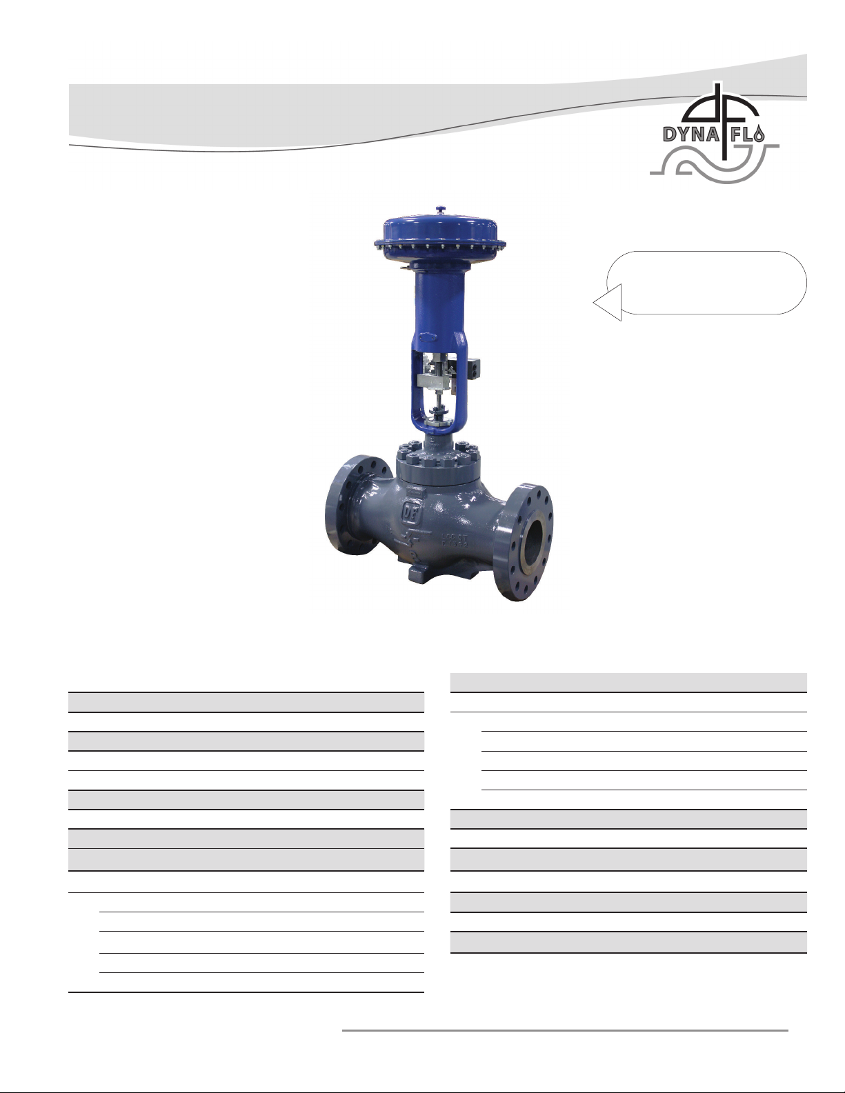
The Model 350/351 control valve is a high capacity single
port, globe style valve, with a bolted type bonnet.
The Model 350H/351H control valve is a high capacity, high
pressure single port, globe style valve, with a bolted
type bonnet.
The standard valve plug action is push down to close.
PTFE Seat and Metal Seat Available.
Consult your Dyna-Flo sales office for other available
configurations.
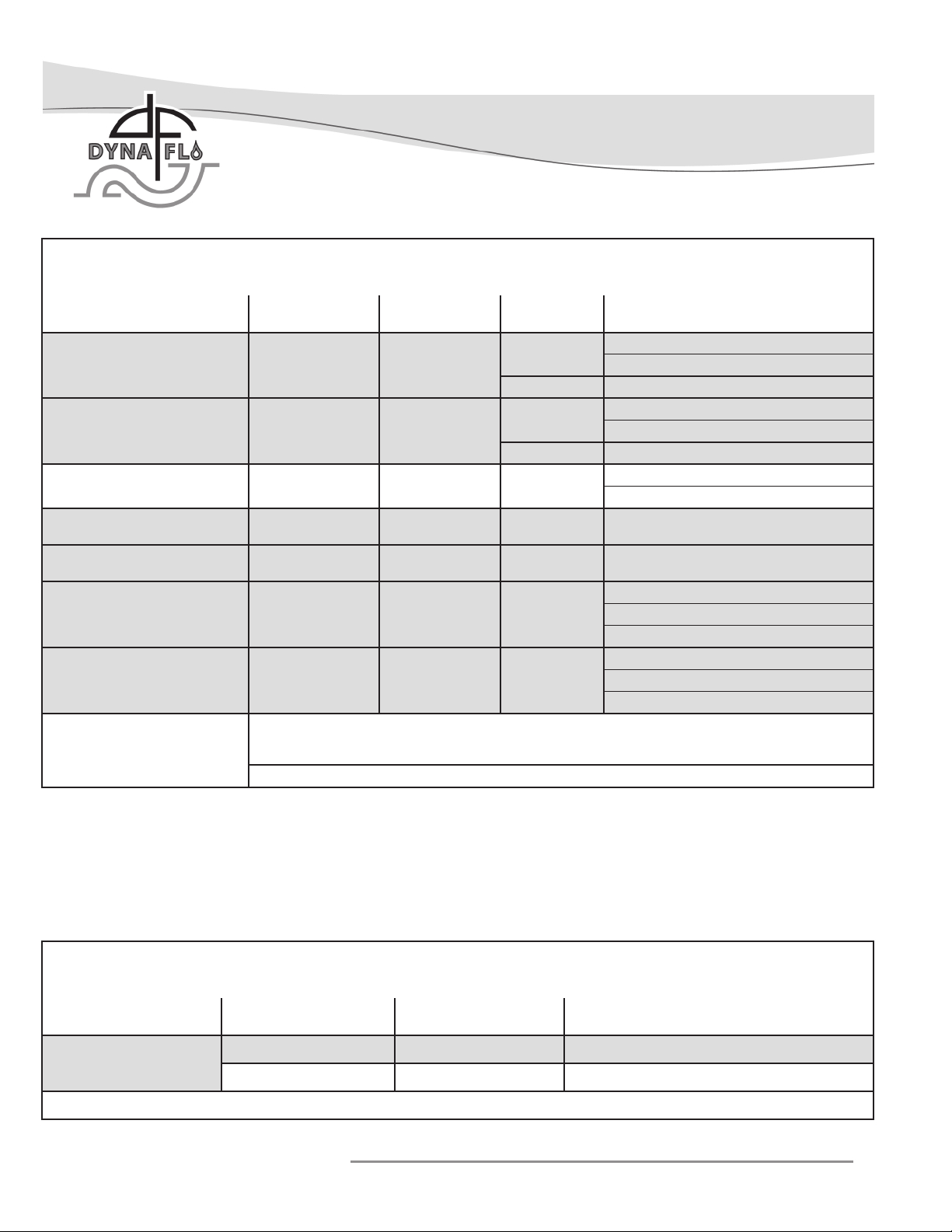
Sizes and Connection Styles
Models: 350, 350H, 351, and 351H
Size:
350, 351: 6x4”, 8x6”, 10x8”, 12x6”, and 12x8”
350H, 351H: 8x6”
Body: Globe
Rating:
350, 351: ASME 150 / 300 / 600
350H, 351H: ASME 900
Connections: RF / RTJ / BWE - Refer to Tables 1 and 2 for
available configurations.
Maximum Inlet Temperature and Pressures
Flanged valves consistent with ASME Class rating as per
ASME B16.34, unless limited as follows:
Temperature Limits: Tables 10, 12, 13, and 14 of Bulletin.
Standard Valve Trim: Figures 11, 12, and 13 of Bulletin.
Low-Noise Valve Trim: Figure 14 of the Sales Bulletin.
Anti-Cavitation Trim: Figure 15 of the Sales Bulletin.
Maximum Pressure Drops
Maximum pressure drop is the same as maximum inlet
pressure unless restricted by the following:
Standard Valve Trim: Figures 11, 12, and 13 of Bulletin.
Anti-Cavitation Trim: Figure 15 of Sales Bulletin.
Low-Noise Valve Trim: Figure 14 of the Sales Bulletin.
NOTE: 8x6 control valves are limited to ASME Class 600 pressure drops
unless used with Anti-Cavitation trim, 8x6 Anti-Cavitation valves are
capable of full Class 900 pressure drops.
Dimensions
Valve and Actuator Outline Dimension Diagram
Refer to Figure 2 of the Sales Bulletin.
Valve and Actuator Assembly Dimensions
Refer to Tables 7 to 9 of the Sales Bulletin.
Characteristic and Flow Direction
•Equal Percentage (Standard) - Flow Down
•Quick Opening - Flow Down
•Linear - Flow Down
•Low-Noise (Linear) - Flow Up
•Anti-Cavitation 1-Stage (Linear) - Flow Down
•Anti-Cavitation 2-Stage (Linear) - Flow Down
Approximate Valve Body Weights
Refer to Table 3.
Materials
Body and bonnet material options include:
LCC (A350-LF2 optional* bonnet material)
WCC (A350-LF2 optional* bonnet material)
WC9 (A182-F22 optional* bonnet material)
CF8M (A182-F316 optional* bonnet material)
*NOTE: Dyna-Flo reserves the right to substitute a cast
material with the forged bar equivalent in the event a casting
is not available.
Refer to Figure 10 of Sales Bulletin for valve construction
material temperature limitations.
Refer to Tables 11 & 12 of the Sales Bulletin for trim
selections.
Cross-Section of the Model 350 & 351 Control Valves
Refer to Figure 34.
Port Diameters and Maximum Valve Plug Travel
Refer to Tables 3 to 5 of the Sales Bulletin.
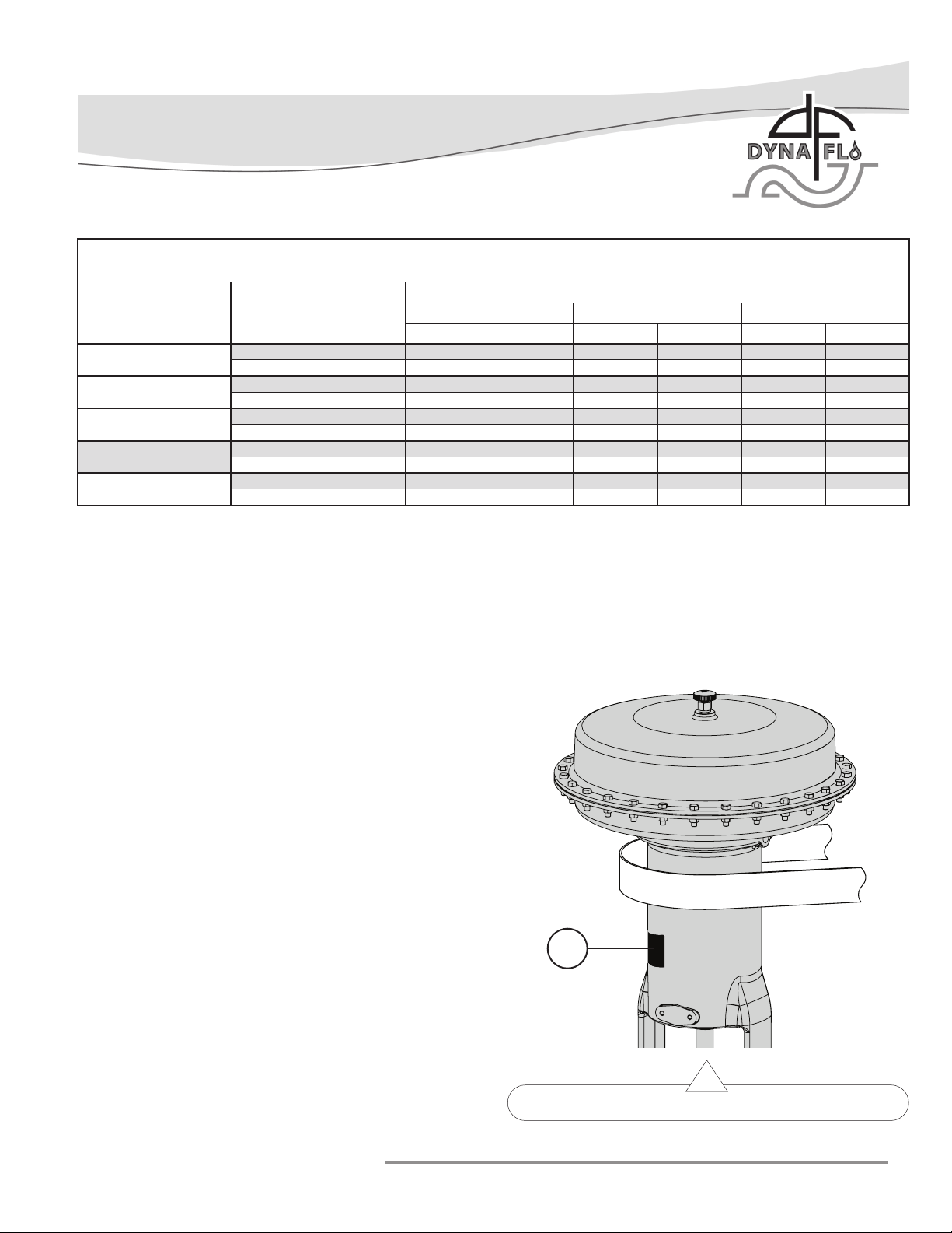
Packing Type
The Standard packing is PTFE V-ring. Live-loaded low
emission, graphite, KALREZ®, and other packing
arrangements are available. Refer to Figures 29, 31, 32, 33.
Maximum Valve Sizing Coefficients
For full list of coefficients refer to document P-CVSM.
Service Application
Refer to Tables 11, 12, & 14 of the Sales Bulletin.
For more information and other options contact your Dyna-Flo
sales office.

Dyna-Flo Control Valve Services Ltd.
Phone: 780 •469 •4000 Toll Free: 1 •866 •396 •2356 Fax: 780 •469 •4035 Website: www.dynaflo.com
Model 350/351 Control Valves
P-350M0620A 4
Operation, Parts, and Instruction Manual
Table 2
Available Valve Configurations for Class VI Shut-Off (in accordance with ASME / FCI 70.2)
Valve Model Port Size
Inch Valve Seat Minimum Seat Load
350
≥3.4375≤7 Metal 300 lbs./lineal inch
≥3.4375≤7 PTFE Consult Dyna-Flo
Note: Class VI shut-off requires special seal materials. Refer to Table 12 of Bulletin for Class VI trim materials.
Table 1
Available Valve Configurations and Shut-Off Class
Valve Model Valve Size
Inch ASME Class Valve Seat Shut-Off Class
(in accordance with ASME / FCI 70.2)
350 6x4, 8x6, 10x8,
12x6, 12x8 150 / 300 / 600 Metal IV (Standard)
V(1) (Optional)
PTFE V (Optional)
350H 8x6 900 Metal IV (Standard)
V(1) (Optional)
PTFE V (Optional)
350 with
Anti-Cavitation 1-Stage
6x4, 8x6, 10x8,
12x6, 12x8 600 Metal IV (Standard)
V (Optional)
350 with
Anti-Cavitation 2-Stage
6x4, 8x6, 12x6,
12x8 600 Metal or
PTFE V
350H with
Anti-Cavitation 2-Stage 8x6 900 Metal or
PTFE V
351 6x4, 8x6, 10x8,
12x6, 12x8 150 / 300 / 600 Metal
II (Standard)
III (Optional)
IV(2)(Optional)
351H 8x6 900 Metal
II (Standard)
III (Optional)
IV(2)(Optional)
Notes:
1- Class V shut-off requires spring-loaded seal ring, radius-seat plug, and wide-bevel seat ring.
Not available for 8 inch port and quick opening trim. Not available with S31600 plug and seat
ring.
2- Class IV shut-off requires multiple graphite piston rings.

Model 350/351 Control Valves
Dyna-Flo Control Valve Services Ltd.
Phone: 780 •469 •4000 Toll Free: 1 •866 •396 •2356 Fax: 780 •469 •4035 Website: www.dynaflo.com
P-350M0620A 5
Operation, Parts, and Instruction Manual
Table 3
Approximate Valve Body Weights
Valve Size
(inch) Connection
ASME Class
150 / 300 600 900
lb Kg lb Kg lb Kg
6x4 Flanged 330 150 430 195 - -
Buttweld - - 270 122 - -
8x6 Flanged 625 284 680 308 1,350 612
Buttweld - - 600 272 1,000 454
10x8 Flanged 1,250 567 1,640 744 - -
Buttweld - - 1,130 512 - -
12x6 Flanged 1,102 500 1,590 721 - -
Buttweld - - 1,160 526 - -
12x8 Flanged 1,440 653 1,890 857 - -
Buttweld - - 1,450 658 - -
UNPACKING VALVE FROM SHIPPING
CONTAINER
Special Tools Required:
• Properly Rated Lifting Straps (2 – 4 Straps) refer to Table 3
and appropriate actuator manual for assembly weights.
• Lifting Device (Example: Crane)
Check the packing list, verify that the list includes all the
materials in the shipping container before unpacking. Valve
information can be found on the nameplate (Key 45). Refer to
Figure 2 for nameplate location.
When lifting the valve from shipping container, place properly
rated lifting straps securely around the neck of the actuator,
refer to Figure 2 for strap placement. Straps should be placed
to avoid damage to tubing and other mounted accessories.
For valve assemblies without an attached actuator, use caution
when lifting or positioning straps so as not to damage the valve
stem.
Lift the valve/actuator assembly using proper lifting techniques. Figure 2 Actuator Lifting Suggestions
LIFTING STRAP
45

Dyna-Flo Control Valve Services Ltd.
Phone: 780 •469 •4000 Toll Free: 1 •866 •396 •2356 Fax: 780 •469 •4035 Website: www.dynaflo.com
Model 350/351 Control Valves
P-350M0620A 6
Operation, Parts, and Instruction Manual
AIR PIPING
WARNING:
Property damage, environmental harm, and personal injury
can result from the use of supply gas other than clean,
non-corrosive, oil and moisture free air. Do not exceed the
supply pressure indicated on the serial plate located on the
actuator (Key 45).
Before You Begin:
Note: Standard actuators accept ¼” (6 mm) NPT connections.
• Refer to the appropriate actuator instruction manual when
necessary.
Piping Installation Steps:
1Use 3/8” (outside diameter) tubing (or equivalent) for air
lines.
2Install the required line vents, valves, drains, seals, and
filters to the actuator.
PERIODIC INSPECTION
Special Equipment Required:
• Bypass or block valves.
Before You Begin:
• Read Safety Caution (Page 2).
• Use safe work practices and lock out procedures.
• Disconnect supply lines (air or gas), electric power, or control
signal to the actuator. Sudden movement of actuator can
cause damage or injury, make sure actuator will not operate.
• Vent any pneumatic actuator loading pressure and relieve
any actuator spring preload if present.
• Relieve process pressure and drain the process fluid from up
and down stream of valve.
• Be aware of potentially hazardous process material that may
be present in-line and in-valve. Isolate the valve from
process pressure. Use a bypass or block valve if necessary,
or completely shut off the process.
INSTALLATION
Before You Begin:
• Read the General and Scope section of this manual (Page 2).
• Read Safety Caution (Page 2).
• Sudden movement of actuator can cause damage or injury.
It helps to have the actuator de-energized.
• Use safe work practices and lock out procedures before
placing valve in-line.
NOTE: For butt weld valve bodies, depending on the body
material, post-weld heat treatment might be required. Soft
parts, seals, some metal trim, threading and shrink-fit parts
can be damaged by post-weld heat treatment. If post-weld heat
treatment is required, it is recommended that all internal valve
parts be removed from the valve body. Contact Dyna-Flo for
more information.
Parts Required:
• Appropriate Line Flange Nuts and Bolts
• Appropriate Line Flange Gaskets
• If the valve has small internal flow passages such as
Anti-Cavitation or Low-Noise trim, the installation of an
upstream strainer should be considered to prevent clogging
of these small passages.
Installation Steps:
1Check the packing box bolting (Key 27 & 39) for proper
tightness. Refer to Packing Installation on Page 22 for
proper packing tightening instructions.
2The valve assembly may be installed in any position
unless limited by vibration considerations, it is however
recommended that the valve be installed with the valve
stem (Key 5) perpendicular to the ground. NOTE: For
some non-vertical orientations, the valve actuator may
need to be supported.
3 Install the valve with flow through the valve in the
direction shown by the flow arrow on the valve body.
4Install the appropriate line flange gaskets.
5Apply Permatex®Nickel Anti-Seize to the threads of the
flange studs and install them.
6When possible, before tightening the line bolting, stroke
the valve and check for smooth operation through the full
stroke. Unsteady valve stem movement could be an
indication of an internal problem.
7Tighten the line flange bolting in even increments in a
crisscross pattern until the correct line bolt torque
specification is reached.

Model 350/351 Control Valves
Dyna-Flo Control Valve Services Ltd.
Phone: 780 •469 •4000 Toll Free: 1 •866 •396 •2356 Fax: 780 •469 •4035 Website: www.dynaflo.com
P-350M0620A 7
Operation, Parts, and Instruction Manual
Inspection Steps:
1Check for visible signs of leakage around all seal and
gasket areas.
2Check the valve for damage, especially damage caused by
corrosive fumes or process drippings.
3Clean and repaint the areas as required.
4Ensure all accessories, mounting brackets, and fasteners
are secure.
5Clean any dirt and foreign material from the valve stem
(Key 5).
1Refer to the appropriate actuator instruction manual for
more information regarding the actuator being removed.
2If the valve has been removed from the pipeline, place
the valve assembly on a flat work surface that can support
the weight.
3Before the actuator is removed, support the actuator using
lifting hooks or straps rated to support the weight of the
actuator.
4If the actuator is a spring and diaphragm actuator,
determine if that actuator is fail open or fail closed. Fail
closed actuators will need to be energized to remove
downward force from the stem connector. Connect a supply
line to the inlet port of the actuator, be sure not to exceed
the maximum casing pressure. Refer to Figure 3 for
recommended needle valve and gauge setup.
5Remove the stem connector (Refer to Figure 5).
6For DFC/DFO: Use a blunted heavy chisel to loosen the
yoke nut (Key 42). Unscrew the yoke nut and remove the
actuator from the valve. If the actuator was energized dur
ing removal, de-energize the actuator (Refer to Figure 4).
For DFLP: Remove the actuator mounting nuts (Key 48)
(Refer to Figure 4a).
7Remove the jam nut and hex nut (Keys 40 & 41) and travel
indicator from the valve stem (Key 5).
Figure 3 Needle Valve with Gauge setup
ACTUATOR REMOVAL
Note: Actuator removal does not require that the valve be
removed from the pipeline.
Tools Needed:
• Properly Rated Lifting Straps or Chains
• Lifting Device (Example: Crane)
Before You Begin:
• Read Safety Caution (Page 2).
• Use safe work practices and lock out procedures.
• Disconnect supply lines (air or gas), electric power, or control
signal to the actuator. Sudden movement of actuator can
cause damage or injury, make sure actuator will not operate.
• Vent any pneumatic actuator loading pressure and relieve
any actuator spring preload if present.
Figure 4 Yoke Nut being loosened with a Chisel
42
43

Dyna-Flo Control Valve Services Ltd.
Phone: 780 •469 •4000 Toll Free: 1 •866 •396 •2356 Fax: 780 •469 •4035 Website: www.dynaflo.com
Model 350/351 Control Valves
P-350M0620A 8
Operation, Parts, and Instruction Manual
MAINTENANCE
Note: Seals, soft parts, and packing (including live loaded
packing) should all be inspected frequently for leaks, wear and
damage. Maintenance to the valve can be performed while the
valve is still in-line, the actuator must be removed to replace
packing (Refer to Page 7 for Actuator Removal instructions).
Before you begin:
• Read Safety Caution (Page 2).
• Determine if the valve has standard or live loaded packing
(Refer to Figures 29, 31, 32, & 33).
• Follow Steps 1 – 6 of Before You Begin from PERIODIC
INSPECTION (Page 7).
Packing Maintenance
If the packing is leaking, proper tightening of the packing may
correct the leak. If re-tightening the packing to the proper
specifications does not stop the leakage it is possible that the
stem or wall of the packing box is damaged. Replace or repair
parts as necessary. For instructions on packing removal only,
refer to the Disassembly, Packing Removal section on Page 9.
1Determine the type of packing installed in the valve. Refer
to Figures 29, 31, 32, & 33 for packing styles.
For Single PTFE V-Ring Packing (Spring-Loaded):
Tighten the packing nuts (Key 39) evenly in an alternating
pattern until the shoulder of the packing follower (Key 36)
makes contact with the top face of the bonnet (Key 24) and
torque value in Table 5 is reached. Refer to Figure 29.
For Double PTFE V-Ring and Graphite Packing:
Tighten the packing nuts (Key 39) evenly in an alternating
pattern to the minimum recommended torque specifications
listed in Table 5 on Page 30, continue tightening until
leakage stops or the maximum torque specification is reached.
If leakage continues after reaching the maximum
recommended torque the packing will need to be replaced,
do not tighten the packing past the maximum recommended
torque as this will cause excessive packing friction.
For Live-Loaded Packing:
Refer to the Sliding Stem Live-Loaded Packing Manual (P-LLPS)
for proper maintenance procedures.
Figure 5 Packing Nut and Stem Connector Detail
Figure 4a DFLP Mounting Nuts & Bolts
39
STEM
CONNECTOR
40
41
48
49

Model 350/351 Control Valves
Dyna-Flo Control Valve Services Ltd.
Phone: 780 •469 •4000 Toll Free: 1 •866 •396 •2356 Fax: 780 •469 •4035 Website: www.dynaflo.com
P-350M0620A 9
Operation, Parts, and Instruction Manual
DISASSEMBLY
Before You Begin:
• Read Safety Caution (Page 2).
• Use safe work practices and lock out procedures.
• Remove the actuator from the valve (Refer to Actuator
Removal Instructions, Page 7).
• Relieve process pressure and drain the process fluid from up
and down stream of valve.
• Be aware of potentially hazardous process material that may
be present in-line and in-valve. Isolate the valve from
process pressure. Use a bypass or block valve if necessary, or
completely shut off the process.
PACKING REMOVAL
For Live Loaded Packing refer to Figure 32 and the Live Loaded
Sliding Stem Packing Manual (P-LLPS).
Special Tools Required:
• Mechanics Pick Set
NOTE: Packing box parts are easier to remove after the bonnet
(Key 24) has been separated from the valve body (Key 1) and
the valve stem (Key 5) has been removed. If the packing is all
that needs to be removed, it is possible to extract packing box
parts carefully using a mechanics pick set.
WARNING: Process medium and pressure may become stored
in the packing, use caution when removing packing parts.
1Remove the packing nuts (Key 39).
2Remove the upper wiper (Key 37) if present, graphite
packing does not include an upper wiper.
3Remove the packing follower (Key 36).
4It is recommended to proceed to the Bonnet Removal
section to continue with valve disassembly. If the packing
is all that needs to be removed, remove the contents of the
packing box (Keys 28 to 35) using a mechanics pick set
being careful not to damage the valve stem (Key 5) or
wall of the packing box of the bonnet (Key 24). For packing
reassembly refer to the Packing Installation section (Page
22).
Figure 6 Packing Removal (Steps 1 - 3)
BONNET REMOVAL
WARNING: Process medium and pressure may be trapped
inside the valve body (Key 1). Use caution when removing the
valve bonnet (Key 24). Refer to Safety Caution on Page 2.
1Loosen the bonnet nuts (Key 36) 1 full turn after contact
between the nuts and the top surface of the bonnet (Key
24) has been broken. Do not remove the bonnet nuts until
any trapped process pressure has been vented. Refer to
Figure 7.
2Break the contact between the valve body (Key 1) and the
bonnet (Key 24) by rocking the bonnet. Use a pry bar or
blunt chisel to help with the separation if necessary.
39
36
38
37
27
24
5

Dyna-Flo Control Valve Services Ltd.
Phone: 780 •469 •4000 Toll Free: 1 •866 •396 •2356 Fax: 780 •469 •4035 Website: www.dynaflo.com
Model 350/351 Control Valves
P-350M0620A 10
Operation, Parts, and Instruction Manual
DISASSEMBLY (Continued)
BONNET REMOVAL (Continued)
3If no process fluid or gas escapes from the body-to-bonnet
joint, proceed by completely removing the bonnet nuts
(Key 26).
4Carefully lift the bonnet (Key 24) from the valve body (Key
1), be sure that the valve stem (Key 5) and plug (Key 3)
assembly do not drop from the bonnet and get damaged.
Also, if the valve plug and stem assembly begin to lift when
lifting the bonnet, it may be necessary to gently tap the
stem from the bonnet using a rubber mallet as the bonnet
is being lifted. NOTE: Use extra caution removing a bonnet
from a valve with a bonnet spacer (Key 23).
5The bonnet gasket (Key 21) may stick to the bonnet during
removal. Remove the bonnet gasket.
Figure 7 Bonnet Removal (Steps 1 - 2)
Figure 8 Bonnet Removal (Steps 3 - 4)
26
24
27
21
5
2
1
26
24
STEP 1
CHISEL

Model 350/351 Control Valves
Dyna-Flo Control Valve Services Ltd.
Phone: 780 •469 •4000 Toll Free: 1 •866 •396 •2356 Fax: 780 •469 •4035 Website: www.dynaflo.com
P-350M0620A 11
Operation, Parts, and Instruction Manual
Figure 9 Bonnet Removal (Valves with Bonnet Spacer)
DISASSEMBLY (Continued)
BONNET REMOVAL (Continued)
6Remove the bonnet spacer (Key 23) if included as part of
the valve assembly. For valves with load rings, refer to the
Trim Parts Removal section below.
TRIM PARTS REMOVAL
1 Remove the metal shim (Key 20) and spiral wound
gasket (Key 19) if they haven’t already been removed.
Refer to Figures 10.
2Remove the valve stem (Key 5) / valve plug (Key 3)
assembly from the valve body (Key 1), refer to Figure 10.
Refer to the Plug Seal Removal section for disassembly
instructions.
3 Carefully remove the cage (Key 18).
4Remove the seat ring (Key 14) and seat ring gasket (Key
13). For Soft Seat valves: Remove the disk retainer (Key
17), PTFE disk (Key 16), disk seat (Key 15), and seat ring
gasket (Key 13). Refer to Figure 11.
5Clean and inspect all parts for damage, especially gasket
seal surfaces. Replace all damaged parts and gaskets with
new parts as necessary, gaskets cannot be reused.
For Low Noise Trim: Remove the valve stem (Key 5) / valve
plug (Key 3), cage retainer (Key 46) or cage retainer assembly
(Key 47) for Low Noise D3 trim, cage (Key 18) and seat ring
(Key 14). Refer to Figure 38.
26
24
21
23
2
46
1
5

Dyna-Flo Control Valve Services Ltd.
Phone: 780 •469 •4000 Toll Free: 1 •866 •396 •2356 Fax: 780 •469 •4035 Website: www.dynaflo.com
Model 350/351 Control Valves
P-350M0620A 12
Operation, Parts, and Instruction Manual
Figure 10 Standard Trim Parts Removal (Steps 1 - 6)
DISASSEMBLY (Continued)
PACKING PARTS REMOVAL
WARNING: Compressed gasses could be trapped between
packing rings.
NOTE: For Live Loaded Packing refer to Figure 32 and the Live
Loaded Sliding Stem Packing Manual (P-LLPS).
1 Using a blunt or rounded tool/rod, carefully tap the
packing parts (Keys 28 to 38) out of the packing bore of
the bonnet (Key 24). A mechanic’s pick set can also be
used to pull packing parts from the bore. Refer to Figure
12.
2Clean and inspect the bonnet for damage, pay particular
attention to the packing bore surface and the gasket
sealing surface. Replace or repair the bonnet as necessary.
Metal packing parts can be reused if they are not
damaged, all other packing parts should be replaced.
Figure 11 Soft Seat Parts Removal
21
A
19 A
A 20
18
17
15
16
13 A
PLUG / STEM
ASSEMBLY
5
3
19
18
13
20
2
1
14

Model 350/351 Control Valves
Dyna-Flo Control Valve Services Ltd.
Phone: 780 •469 •4000 Toll Free: 1 •866 •396 •2356 Fax: 780 •469 •4035 Website: www.dynaflo.com
P-350M0620A 13
Operation, Parts, and Instruction Manual
Figure 12 Packing Parts Removal (Step 1)
BLUNT
ROD
24
DISASSEMBLY (Continued)
PLUG SEAL REMOVAL
For Model 350 Two-Piece Plug Seal Ring Assemblies:
NOTE: 8 inch valve assemblies have only one-piece plug seals,
they only use a seal ring (Key 8).
1Using a sharp knife, lightly cut the surface of the seal ring,
then pry or twist the cut groove with a small screwdriver.
This will break the seal ring and allow for easy removal
without damaging the seal groove of the plug.
Figure 13 Two-Piece Plug Seal Ring Removal (Model 350)
For Model 350 Three-Piece Seal Ring Assemblies:
NOTE: 8 inch valve assemblies have only one-piece plug seals,
they only use a seal ring (Key 8).
1Carefully remove the retaining ring (Key 10) from the plug
groove, a pick set or flat screw driver may be required to
pry the spiral rings of the retaining ring apart to assist
removal. Refer to Figure 14.
2Remove the backup ring (Key 9).
3Remove the seal ring (Key 8).
2Use the same process as described in Step 1 to remove the
backup ring (Key 6). WARNING: Seal ring groove in the
plug (Key 3) is a critical area and damage to the area may
reduce or eliminate the sealing function of the plug. Refer
to Figure 13.
7
6
3A
DETAIL A
WARNING: AREA IN
BOLD IS A CRITICAL
AREA. DAMAGE TO THE
AREA MAY REDUCE OR
ELIMINATE THE SEALING
FUNCTION OF THE PLUG.

Dyna-Flo Control Valve Services Ltd.
Phone: 780 •469 •4000 Toll Free: 1 •866 •396 •2356 Fax: 780 •469 •4035 Website: www.dynaflo.com
Model 350/351 Control Valves
P-350M0620A 14
Operation, Parts, and Instruction Manual
DISASSEMBLY (Continued)
PLUG SEAL REMOVAL (Continued)
For Model 350 Three-Piece Plug Seal Ring Assemblies
with Anti-Extrusion Rings:
1Carefully remove the retaining ring (Key 10) from the plug
groove, a pick set or flat screw driver may be required to
pry the spiral rings of the retaining ring apart to assist
removal. Refer to Figure 14.
2Remove the backup ring (Key 9).
3 Remove the anti-extrusion ring (Key 11). The anti-
extrusion ring is two pieces and only included in valve
assemblies rated for over 450°F (232°C).
4Remove the seal ring (Key 8).
For Model 351 Valves (Refer to Figure 15):
1Remove the piston rings (Key 12). NOTE: Piston rings are
broken in half and can be easily pulled apart.
Figure 14
Three-Piece Plug Seal
Removal (Model 350 Only)
For All Models:
Clean and inspect all parts for damage, especially the stem
(Key 5) and plug (Key 3) surfaces. Minor scratches can be
buffed or lapped out, major scratches (scratches that will stop
a finger nail) will need to be machined or replaced. Replace all
damaged parts and soft parts with new parts.
Figure 15 Model 351 Piston Ring Removal
LAPPING
Expect a certain amount of leakage in valves with metal
seats. In some cases where leakage has become excessive,
lapping can improve sealing performance. Before performing
the lapping process, insure all trim parts have been thoroughly
cleaned and are free of debris. Do not lap soft seat valves.
NOTE: Spiral wound gaskets (Key 19) make their seal by being
crushed and cannot be reused, this includes gaskets required to
be used during the lapping process. It may be desirable to use
an already crushed gasket in the lapping process to be replaced
with new gaskets during reassembly.
CAUTION: Once lapping has been performed with a previously
crushed gasket, it is important to mark the position and
alignment of all trim parts (Keys 3, 14, and 18) before
removal and reassembly. If trim parts are reassembled out of
their lapped alignment excessive leakage may result.
10
9
8
3
5
11*
*Only included in valve
assemblies rated over
450°F (232°C).
5
12
3

Model 350/351 Control Valves
Dyna-Flo Control Valve Services Ltd.
Phone: 780 •469 •4000 Toll Free: 1 •866 •396 •2356 Fax: 780 •469 •4035 Website: www.dynaflo.com
P-350M0620A 15
Operation, Parts, and Instruction Manual
LAPPING (Continued)
Special Tools Required:
• Soft felt marker
• Two wrenches that will slide over the valve stem (Key 5)
• 400 – 600 grit (fine grit) Loctite®Clover®compound (Key D)
Lapping Procedure
1Install the used seat ring gasket (Key 13) into the valve
body (Key 1).
2Install the seat ring (Key 14). Mark the position of seat
ring using the marker.
3Install the cage (Key 18). Mark the position of cage using
the marker.
4Do not install any plug seals into the valve plug (Key 3).
Apply fine grit Clover®compound to the seating surface of
the valve plug. Install the valve plug/stem assembly
(Keys 3, 4, 5) into the valve. Mark the position of the
plug/stem assembly using the marker.
5Install used bonnet gaskets (Keys 19, 20, & 21).
6Carefully lift the bonnet (Key 24) into place and secure the
bonnet using half of the bonnet nuts (Key 26). Mark the
position of the valve plug (Key 3) on the bonnet (Key 24)
using the marker.
7Install the packing follower (Key 36).
8Install the jam nut (Key 40) on to the valve stem (Key 5)
and build a handle as shown in Figures 16 and 18
using the two wrenches and the hex nut (Key 41).
9Rotate the valve plug (Key 3) back and forth about
a quarter of a full rotation (only a small amount of
movement is required, do not make full rotations)
over the seat ring (Key 14) using the wrench handles.
10 If a seat leak test is to be performed after lapping to test
valve shut off, disassemble the lapping setup after a few
cycles of back and forth plug movement. Clean the lapping
compound from inside the valve. Replace the used
gaskets (Keys 13, 19, 20, & 21) with new gaskets and
reassemble the valve for testing. NOTE: Another set of
new gaskets will need to be used for the final valve
assembly if the lapping procedure needs to be repeated
after seat leak testing.
Figure 16 Lapping Procedure Setup (Steps 1 - 8)
Figure 17 Lapping Compound Application
40
36
24
5
41
26
2
1
19 18
3
13
14
WRENCH
WRENCH
5
3
APPLY FINE
GRIT CLOVER®
COMPOUND
(KEY D) TO
THE SEATING
SURFACE OF
THE PLUG

Dyna-Flo Control Valve Services Ltd.
Phone: 780 •469 •4000 Toll Free: 1 •866 •396 •2356 Fax: 780 •469 •4035 Website: www.dynaflo.com
Model 350/351 Control Valves
P-350M0620A 16
Operation, Parts, and Instruction Manual
Figure 18 Lapping Procedure Setup (Steps 8 - 10)
STUD INSTALLATION
1If the studs (Key 2) were replaced, removed, or never
installed, apply nickel anti-seize (Key A) to the threads
of the end of the stud without a material stamp.
2Thread the studs (Key 2) into the valve body (Key 1)
nickel anti-seize coated end first, until they are completely
threaded into the valve body.
PLUG SEAL ASSEMBLY
For Model 350 Two-Piece Plug Seal Ring Assemblies:
Note: Two-piece seals are not available for 8 inch valves.
1Apply Lubriplate®No. 105 (Key C) to the surface of the
backup ring (Key 6).
2Carefully slide the backup ring (Key 6) over the top of the
valve plug (Key 3) and into the groove. Refer to Figure
19.
3Apply Lubriplate®No. 105 (Key C) to the seal ring (Key
7). Carefully slide the seal ring over the top edge of the
valve plug (Key 3) and into the groove, refer to Figure 19.
4Allow time for the seal ring (Key 7) to shrink back to its
original size after installation.
5Before installing the plug/stem assembly into the valve,
apply Lubriplate®No. 105 (Key C) to the outside surface
of the plug (Key 3) as shown in Figure 19.
For Model 350 Three-Piece Plug Seal Ring Assemblies:
1Apply Lubriplate®No. 105 (Key C) to the surface of the
seal ring (Key 8).
2Install the seal ring (Key 8) onto the valve plug (Key 3),
refer to Figure 20 for proper seal ring orientation. NOTE:
8 inch valves are technically one-piece plug seals, 8 inch
valve assemblies use a seal ring only and do not make use
of a backup ring (Key 9) or retaining ring (Key 10).
4Apply Lubriplate®No. 105 (Key C) to the backup ring
(Key 9) and install the backup ring onto the valve plug
(Key 3).
5Apply Lubriplate®No. 105 (Key C) to the retaining ring
(Key 10) and install the retaining ring into the retaining
ring groove on the valve plug (Key 3).
6Install the plug assembly into the cage (Key 18).
ASSEMBLY
Before You Begin:
• Read Safety Caution (Page 2).
• Use safe work practices and lock out procedures.
• Clean and inspect all parts.
• Replace or repair damaged parts. Replace all soft parts
(Seals, o-rings, gaskets, live loaded packing).
Lubricants Required:
• Permatex®Nickel Anti-Seize or equivalent (Key A)
• Dow Corning Molykote®111 or equivalent (Key B)
• Lubriplate®No. 105 Grease or equivalent (Key C)
41
40
26
1
24
2
27
36
5
WRENCH
WRENCH

Model 350/351 Control Valves
Dyna-Flo Control Valve Services Ltd.
Phone: 780 •469 •4000 Toll Free: 1 •866 •396 •2356 Fax: 780 •469 •4035 Website: www.dynaflo.com
P-350M0620A 17
Operation, Parts, and Instruction Manual
Figure 19 Two-Piece Plug Seal Assembly (Model 350 Only)
Figure 20 Three-Piece Plug Seal Assembly (Model 350 Only)
5
7 C
6 C
33C
NOTE: APPLY GREASE
TO ENTIRE OUTSIDE
SURFACE OF PLUG
BEFORE INSTALLATION.
6
7
10C
9C
8C
3C
9
10
8
SPRING-LOADED SEAL RING
FOR FLOW DOWN VALVES
THE “CUP” OF THE SEAL RING
(KEY 8) FACES DOWN.
SPRING-LOADED
SEAL RING
FOR FLOW UP
VALVES THE “CUP”
OF THE SEAL RING
(KEY 8) FACES UP.
NOTE: APPLY
GREASE TO
ENTIRE
OUTSIDE
SURFACE OF
PLUG.
SPRING-LOADED SEAL RING
FOR BI-DIRECTIONAL
VALVES THE “CUP” OF THE
SEAL RINGS (KEY 8) FACE
EACH OTHER.
9
9
5

Dyna-Flo Control Valve Services Ltd.
Phone: 780 •469 •4000 Toll Free: 1 •866 •396 •2356 Fax: 780 •469 •4035 Website: www.dynaflo.com
Model 350/351 Control Valves
P-350M0620A 18
Operation, Parts, and Instruction Manual
Figure 21 Plug Seal Assembly with Anti-Extrusion Ring
ASSEMBLY (Continued)
PLUG SEAL ASSEMBLY (Continued)
For Model 350 Three-Piece Plug Seal Ring Assemblies
with Anti-Extrusion Rings:
1Apply Lubriplate®No. 105 (Key C) to the surface of the
seal ring (Key 8).
2Install the seal ring (Key 8) onto the valve plug (Key 3),
refer to Figure 21 for proper seal ring orientation. NOTE:
8 inch valves are technically one-piece plug seals, 8 inch
valve assemblies use a seal ring only and do not make use
of a backup ring (Key 9) or retaining ring (Key 10).
3Apply Lubriplate®No. 105 (Key C) to the anti-extrusion
ring (Key 11) and install the anti-extrusion ring on to the
valve plug as shown in Figure 21. NOTE: Anti-extrusion
rings are only used for valve assemblies rated to exceed
450ºF (232ºC).
4Apply Lubriplate®No. 105 (Key C) to the backup ring
(Key 9) and install the backup ring onto the valve plug
(Key 3).
5Apply Lubriplate®No. 105 (Key C) to the retaining ring
(Key 10) and install the retaining ring into the retaining
ring groove on the valve plug (Key 3).
6Allow time for the seal ring material to shrink back to its
original size after being stretched over the valve plug
before installing the plug assembly into the cage (Key 18).
For Model 351 Valves:
NOTE: Replacement piston rings (Key 12) come in one piece.
Before installation it is necessary to break the piston ring into
two pieces. Do not saw or cut the piston rings. Use caution
when breaking piston rings as they can be easily damaged.
Piston Ring Vise Break Method:
Piston rings (Key 12) can be broken into two pieces using a vise
with smooth jaws or jaw softeners.
Special Tools Required:
- Vise
- Electrical Tape
1Wrap electrical tape once around the outside diameter of
the piston ring (Key 12). Electrical tape will help contain
the piston ring while it is being broken. Refer to Figure 23.
2Place the piston ring into the jaws of the vise as shown in
Figure 24.
3Slowly compress the piston ring in the vise until the ring
snaps on both sides. If one side of the piston ring snaps
first, continue compressing the piston ring until the other
side snaps as well. Refer to Figure 22 for installation.
Piston Ring Scoring Break Method:
If no vise is available, piston rings (Key 12) can be scored with
a knife and broken over a hard surface. Do not saw or cut the
piston rings in half.
1Wrap electrical tape once around the outside diameter of
the piston ring (Key 12). Electrical tape will help contain
the piston ring while it is being broken. Refer to Figure 23.
2Score (do not cut) the top surface of the piston ring.
3Place half of the piston ring over the edge of a hard surface
(such as a table edge) so that the score marks are in a
parallel line with the edge of the hard surface.
4Apply downward pressure to both sides of the piston ring
until it snaps in half.
5Remove the electrical tape. Install each half of the broken
piston ring into the piston ring groove in the valve plug
(Key 3). Refer to Figure 22.
10
C
9
C
11
C
8
3
NOTE: KEY
11 IS TWO
PIECES AND
MUST BE
ARRANGED
AS SHOWN.
FLOW DOWN
ORIENTATION
FLOW UP
ORIENTATION

Model 350/351 Control Valves
Dyna-Flo Control Valve Services Ltd.
Phone: 780 •469 •4000 Toll Free: 1 •866 •396 •2356 Fax: 780 •469 •4035 Website: www.dynaflo.com
P-350M0620A 19
Operation, Parts, and Instruction Manual
Figure 23 Model 351 Piston Ring Vise Break Method (Step 1) Figure 24 Model 351 Piston Ring Vise Break Method (Step 2)
Figure 22 Model 351 Piston Ring Installation
NOTE: APPLY GREASE TO ENTIRE OUTSIDE SURFACE
OF PLUG.
125
C
3
NOTE: STAGGER THE
BREAKS IN THE PISTON
RINGS.

Dyna-Flo Control Valve Services Ltd.
Phone: 780 •469 •4000 Toll Free: 1 •866 •396 •2356 Fax: 780 •469 •4035 Website: www.dynaflo.com
Model 350/351 Control Valves
P-350M0620A 20
Operation, Parts, and Instruction Manual
ASSEMBLY (Continued)
TRIM PARTS ASSEMBLY
NOTE: The spiral wound gasket (Key 19) makes its seal by
being crushed and cannot be reused.
1Apply nickel anti-seize (Key A) to the seat ring pocket
of the valve body (Key 1). Install the seat ring gasket (Key
13) into the valve body (Key 1). Apply nickel anti-seize
(Key A) to the top of the seat ring gasket (Key 13). Refer
to Figure 25.
4 Install the seat ring (Key 14) into the valve body (Key 1).
For Soft Seat Valves: Install the disk seat (Key 15) onto
the seat ring gasket (Key 13). Install the PTFE disk (Key
16) onto the disk seat. Install the disk retainer (Key 17)
onto the PTFE disk. Refer to Figure 11.
5Install the cage (Key 18).
6Apply Lubriplate®No. 105 (Key C) to the side of the valve
plug (Key 3) (Refer to Figures 19, 20, 21, & 22). Install the
valve plug assembly into the cage (Key 18) (Refer to Figure
25).
7Apply nickel anti-seize (Key A) to the gasket surface of
the cage (Key 18) and top surface of the spiral wound
gasket (Key 19), metal shim (Key 20), and bonnet gasket
(Key 21). Install the gaskets and shim as shown in Figure
25.
For 8 Inch Valves: Apply nickel anti-seize (Key A)
to the gasket seating surface of the valve body (Key 1)
and top surface of the bonnet gasket (Key 21) and install.
Install the load ring (Key 22). Refer to Figure 37.
For Low-Noise Valves: Install the bonnet spacer (Key
23) as shown in Figure 38. Apply nickel anti-seize (Key A)
to the gasket seating surface of the bonnet spacer (Key
23) and top surface of the bonnet gasket (Key 21) and
install. Install the load ring (Key 22).
Figure 25 Trim Parts Assembly
ASSEMBLY (Continued)
BONNET INSTALLATION
Before You Begin:
• Read Safety Caution (Page 2).
• Clean and inspect all parts.
• Replace or repair damaged parts. Replace all soft parts
(Seals, o-rings, gaskets, live loaded packing).
A 21
20 A
A 19
A
A
14
18 2
5
7
3
13 A
1
A
This manual suits for next models
3
Table of contents
Other Dyna-Flo Control Unit manuals

Dyna-Flo
Dyna-Flo 570 Parts list manual

Dyna-Flo
Dyna-Flo 361 Parts list manual

Dyna-Flo
Dyna-Flo 4000 Parts list manual

Dyna-Flo
Dyna-Flo 570 Parts list manual

Dyna-Flo
Dyna-Flo 390 Parts list manual

Dyna-Flo
Dyna-Flo 590 Parts list manual

Dyna-Flo
Dyna-Flo DF269 Parts list manual

Dyna-Flo
Dyna-Flo 360 Parts list manual

Dyna-Flo
Dyna-Flo 590 Parts list manual
Popular Control Unit manuals by other brands

National Instruments
National Instruments PXIe-6591R Getting started guide

Vetter
Vetter Smartfork operating instructions

Humminbird
Humminbird Helix Series installation guide

SMC Networks
SMC Networks AV2000 manual

Bosch
Bosch DCU 220 Original instructions

Matrix Orbital
Matrix Orbital GLK24064-25 Technical manual