Dyna-Flo Control Valve Services Ltd.
Phone: 780 •469 •4000 Toll Free: 1 •866 •396 •2356 Fax: 780 •469 •4035 Website: www.dynaflo.com
Model 590 Control Valve
P-590M0817A 8
Operation, Parts, and Instruction Manual
PERIODIC INSPECTION
Special Equipment Required:
• Bypass or block valves.
Before You Begin:
• Read Safety Caution (Page 2).
• Use safe work practices and lock out procedures.
• Disconnect supply lines (air or gas), electric power, or control
signal to the actuator. Sudden movement of actuator can
cause damage or injury, make sure actuator will not operate.
• Vent any pneumatic actuator loading pressure and relieve
any actuator spring preload if present.
• Relieve process pressure and drain the process fluid from up
and down stream of valve.
• Be aware of potentially hazardous process material that may
be present in-line and in-valve. Isolate the valve from
process pressure. Use a bypass or block valve if necessary,
or completely shut off the process. For dual seal valves,
relieve internal pressure by removing the pipe plug (Key 37).
See Figure 38 on Page 32.
Inspection Steps:
1Check for visible signs of leakage around all seal and
gasket areas.
2Check the valve for damage, especially damage caused by
corrosive fumes or process drippings.
3Clean and repaint the areas as required.
4Ensure all accessories, mounting brackets, and fasteners
are secure.
5Clean any dirt and foreign material from the valve shaft
(Key 17).
MAINTENANCE
Note: Shaft seals or live loaded packing and ball seals (Key 30)
should all be inspected frequently for leaks, wear and
damage. Maintenance to the shaft seals or live loaded packing
can be made while the valve is still in-line, the actuator must
be removed for drive shaft (Key 17) seal/pacing maintenance
(See Page 12 for Actuator Removal instructions).
Note: Perform ball seal (Key 30) maintenance when the control
valve will not properly shut off. Ball seal maintenance can be
performed without removing the actuator from the valve. Ball
seal maintenance cannot be performed with the valve in-line.
When removing the valve from pipe line be sure it is in the
OPEN position, verify the valve is open using the indicator
scale (Key 24) before removing from line.
Note: When testing the seal integrity of the valve using the
pipe plug port (dual seal configuration), it is recommended that
the pipe plug (Key 37) be replaced by a hand valve. A hand
valve will allow valve pressure to be relieved safely during
seat leak rate testing. See Figure 38 for pipe plug location.
Before You Begin:
• Read Safety Caution (Page 2).
• Determine if valve has shaft seals or live loaded packing
(See Figures 31 & 37).
• Determine if valve is single seal or dual seal (See Figures 37
& 38).
• Follow Steps 2 – 5 of PERIODIC INSPECTION Before you
begin.
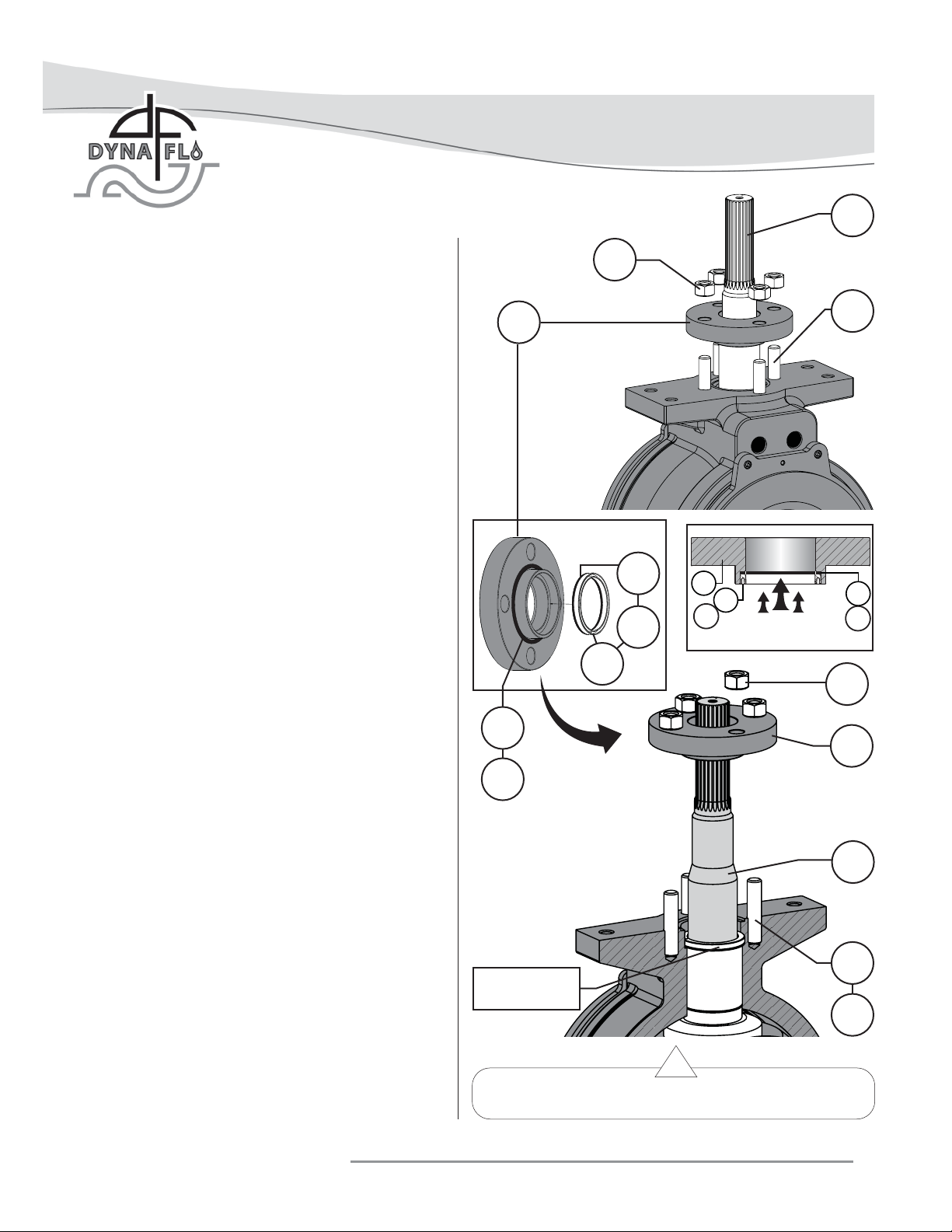
SHAFT SEAL MAINTENANCE
Note: It is recommended that the follower shaft seal and the
drive shaft seal be replaced at the same time. The actuator
must be removed for drive shaft seal maintenance. For live
loaded packing see Page 25.
Special Tools Required:
• Mechanics Pick Set
Lubricants Required:
• Anti-Seize Compound (Key A)
• Silicone-based O-Ring Compound (Key B)
• White Petroleum Grease (Key C)