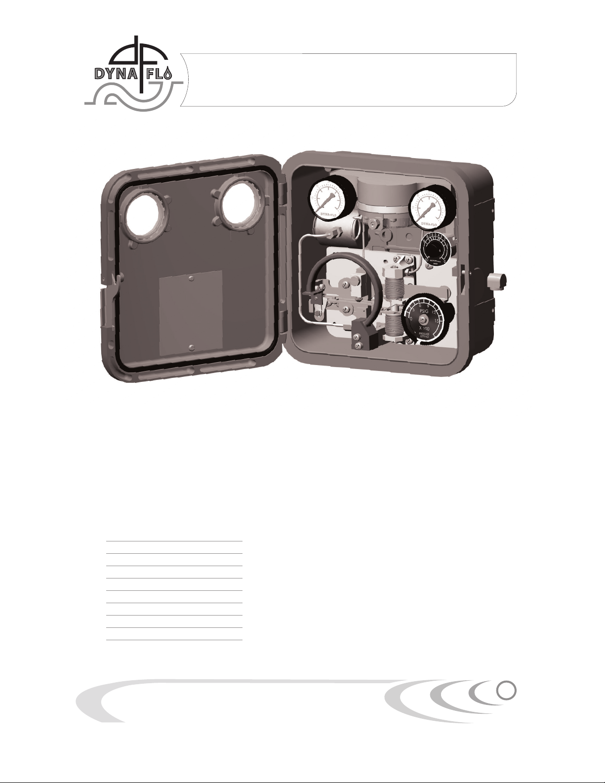
Model
4000 Pressure Controller
Operation, Parts and Instruction Manuals
Dyna-Flo Control Valve Services Ltd.
Edmonton, Alberta, CANADA
Website: www.dynaflo.com
Phone: 780 • 469 • 4000
Toll Free: 1 • 866 • 396 • 2356
Fax: 780 • 469 • 3149
Instruction Manual October 2005
8
Relay Manifold
Replacement
Refer to Figure 4.
A Always shut down the supply, control and p
process pressure line to the controller.
B Disconnect the relay tubing (Key 58) from the
relay manifold (Key 56).
C Remove the relay manifold (Key 56) from the
case by unscrewing the 2 retaining screws
(Key 39 - not shown) on the back of the case.
D Remove the gauges, proportional band, and
elbow fitting from the manifold. Install the
gauges, proportional band, and elbow fitting
into the new replacement manifold.
E Replace the relay manifold o-rings (Key 57).
Place the o-rings on the inlet and outlet fittings
on the relay manifold. With the manifold in
place, insert and fasten the 2 screws (Key 39-
not shown) from the backside of the case.
F Connect the tubing, and check all connections
for leaks.
G Perform calibration procedure.
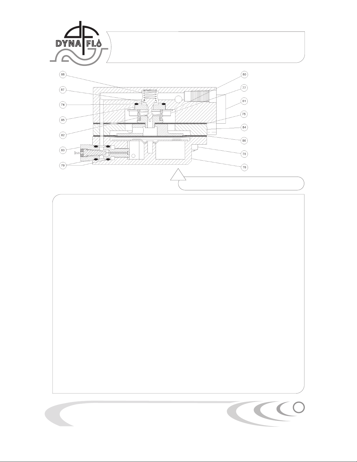
Relay Reconditioning
Refer to Figure 3.
Disassembly
A Complete steps A through D of relay manifold
replacement.
B Unscrew the orifice assembly (Key 83). Remove
the o-rings (Key 79) from the orifice assembly.
C Place the relay manifold on the work surface
with the casing screws facing up. Remove the
casing screws (Key 78), in a criss-cross
pattern.
D Remove and separate the lower casing (Key
76) bottom diaphragm (Key 86), spacer ring
(Key 84), diaphragm assembly (Key 75), relay
spring (Key 82), and valve plug spring (Key 88)
from the relay manifold (Key 81).
E Inspect the valve seats (under a good light) for
roughness due to corrosion. One seat is located
in the diaphragm assembly (Key 75), and the
other seat is located on the seat ring (Key 85),
which is found in the relay manifold (Key 81).
Replace the diaphragm assembly or seat ring
if seats are damaged or worn.
F To install a replacement seat ring (Key 85) in
the relay manifold, remove the 3 screws (Key
77) and washers (Key 80) retaining the seat
ring. Remove the seat ring (Key 85), and o-ring
(Key 74) from the seat pocket in the relay
manifold.
G Inspect diaphragms and gaskets, and replace
them if necessary.
H Replace the spring and valve plug if they show
signs of corrosion.
I The lower diaphragm is part of the diaphragm
assembly and must be replaced as an assembly.
J Clean all parts thoroughly before re-assembling.
Re-assembly
A With the opening in the relay manifold facing
up, place the valve plug spring in the bottom of
the manifold. Carefully place the valve plug on
top of the spring, such that the plug is pointing
up.
B Install the seat o-ring in the pocket of the relay
manifold. Carefully place the seat ring on top
of the o-ring, ensuring the plug is sticking
through the seat ring.
C With the seat ring in place, install the 3
screws and washers that retain the seat ring.