All rights reserved. Reproduction or issue to third parties in any form whatsoever is not permitted without written authority from the proprietors.
7
3) Operation and Installation
3.1) General
The general sensor connector configuration is given below;
Cable Code/Pin Configuration:
• Red : V + Power supply voltage +6 to +20VDC.
• Black : Ground Power GND
• White : Signal Out
• Blue : nc Not Connect
WARNING
Never connect the power supply and the power ground to white.
Never connect the power supply to the power ground.
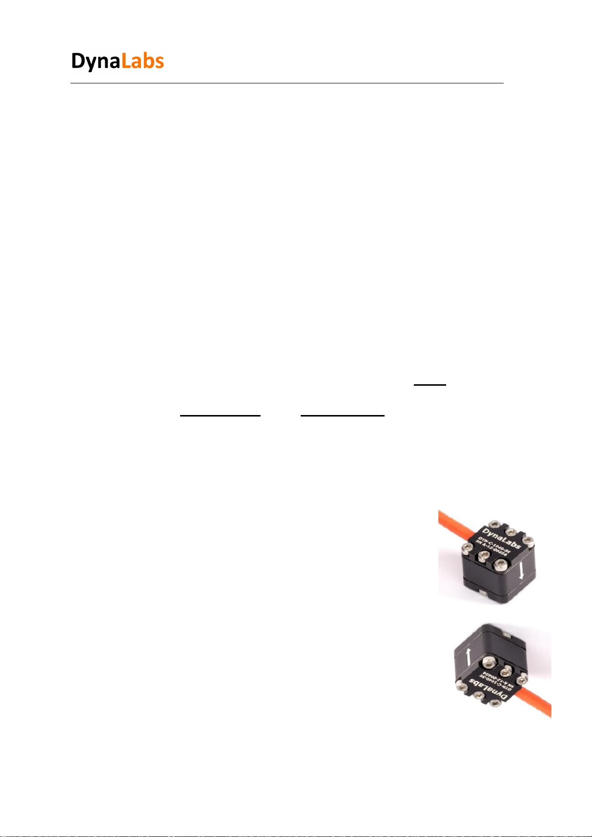
4) Sensor Static Calibration Verification
Using gravity, voltage values are measured in the + and - directions, providing a
value of 1 g. The measurement should be made as follows;
When the sensitivity value of 1000SE series sensors are entered
to the data acquisition system, the sensor shows +1 g
with the effect of gravity in the direction of the arrow sign.
When the sensor is in the opposite direction of the arrow,
it shows -1 g with the effect of gravity.
Using gravity, the voltage values that provide 1 g in the + and -
directions are measured and compared with the catalog value.
The calibration value should be close to the catalog value with a
10% tolerance. Sensor catalog sensitivity values are given in
Table 1.