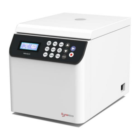
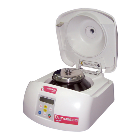
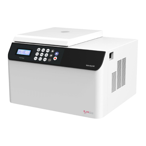
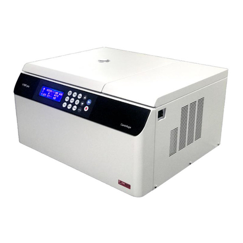
Dynamica VELOCITY15R Pro User manual

Benchtop Centrifuge
Instruction manual
Model VELOCITY15R Pro Benchtop Centrifuge
V1.0
VELOCITY15R Pro


VELOCITY15R Pro BENCHTOP CENTRIFUGE
Thank you very much for choosing Dynamica Velocity15R Pro centrifuge. Please
carefully read through this instruction manual before using this centrifuge.
Appearance or specification is subject to change without notice.
Dynamica


i
Safety Reminder
Symbol is the general international safety sign, please read carefully the following
safety precautions. Follow the instructions and procedures described in this manual to
operate this centrifuge safely.
⚫Read all safety Warnings and Cautions in this manual carefully.
⚫Safety messages are labeled as follows. The safety symbol is in combination
with words of “WARNING” and “CAUTION” to notify users the potential danger; Please
read those instruction carefully before using the centrifuge for the first time.
WARNING: Personal danger
Warning notes indicate any condition or practice, which if not strictly observed, could
result in personal injury or possible death.
CAUTION: Instrument damage
Caution notes indicate any condition or practice, which if not strictly observed or
remedied, could result in damage or destruction of the equipment.
NOTE: Need to be noted generally.
⚫Do not operate the centrifuge in a way which is not described in this manual. Please
contact our service personnel if you have any question.
WARNING:
⚫This centrifuge is not explosion-proof. Never use explosive or flammable samples.
⚫Do not install the centrifuge in or near places where inflammable gases are
generated or chemicals are stored.
⚫Make sure to prepare necessary safely measures before using samples that are
toxic, radioactive or contaminated with pathogenic micro-organisms.
⚫If the instrument, the rotor and or accessories that has been contaminated by
solutions with toxic, radioactive or pathogenic materials, clean it according to the
decontamination procedure that you specified.
⚫If the contaminated equipment requires service of Dynamica or authorized agency
of Dynamica, either at the customer’s site, Dynamica or at the agent facilities, sterilize
and decontaminate it in advance. Make sure to notify the service representatives of the
use of such materials.
⚫Do not touch the power cord or switch with wet hands to avoid electrical shocks.
⚫Users or any hazardous materials are recommended to keep 30cm away from the

ii
centrifuge when it is operating.
⚫Never forcedly release the door lock while the rotor is rotating.
Unauthorized repairs, disassembly, and other services applied to the centrifuge are
strictly prohibited.
CAUTION:
⚫The centrifuge must be located on the firm and level table.
⚫Be careful not to get your fingers or hands caught between the door hook and the
table when closing the door.
⚫When opening the door, make sure the angle between door and the shell is more
than 70 degree.
⚫Do not move or relocate this centrifuge while the rotor is rotating.
⚫If there is liquid in the chamber, dry it immediately to avoid contaminating the
sample.
⚫Keep the chamber clean and remove any objects before running the instrument.
⚫Cautions on rotors:
1)Always check for corrosion and damages on the rotor surface before using it. Do
not use the rotor or bucket if such abnormality is found.
2)Do not run this centrifuge over the allowable maximum speed of the rotor, buckets,
and adapters. If their maximum speeds vary, run it at the lowest maximum speed
among them.
3)Do not exceed the allowable imbalance.
4)Make sure the tubes and bottles within their actual capacities.
5)Make sure all the buckets are the same type at all times.
6)If the rotor is provided with a cover, make sure it is tightly rotated on the rotor
before the operation.
7)Use recommended rotors only.
⚫If any abnormal condition occurs during operation, stop it immediately and contact
our service representative. Notify the service representative the error code.
⚫Earthquakes may cause damage to the centrifuge. Contact our service
representative if abnormality observed.

iii
Contents
Safety Reminder..........................................................................................................i
1 Specification......................................................................................................................1
2 Operational Condition.......................................................................................................2
2.1 Basic operational conditions...................................................................................2
2.2 Transport and storage condition.............................................................................2
3 Installation.........................................................................................................................3
3.1 Location..................................................................................................................3
3.2 Connection of the power cord and grounding........................................................3
4 Structure ...........................................................................................................................4
5 Operation panel ................................................................................................................6
6 Preparation of Rotor .........................................................................................................8
7 Operation........................................................................................................................10
7.1 Normal Operation.................................................................................................10
7.2 Pulse Operation....................................................................................................13
8 Maintenance ...................................................................................................................15
8.1 The daily maintenance .........................................................................................15
8.2 Periodic inspect and replace consumable parts ..................................................16
9 Troubleshooting ..............................................................................................................17
9.1 Common error list.................................................................................................17
10 Frequent problems and solutions.................................................................................18
10.1 How to open the door.........................................................................................18
11Applicable rotors and tubes...........................................................................................19
11.1 Table of applicable rotors....................................................................................19
11.2 Cleaning and sterilizing tubes and bottles..........................................................20
12 Rotating radius of applicable rotors..............................................................................22
13 Calculating relative centrifuge force (RCF)..................................................................22
14 Circuit connecting graph...............................................................................................23
15 Guarantee.....................................................................................................................24
After-sales Service.............................................................................................................24

1
Maximum speed
15,000rpm
Maximum RCF
22,302×g (FA15M)
Maximum capacity
10×5ml (FA15N)
Timer
1minute~99minute/HOLD mode
Temperature Range
-20℃~45℃
Driving system
AC Motor
Safety features
Cover door with dual-locks, over-speed protection, overheat
protection and imbalance protection, situation diagnosis
system
Power requirements
230V: Single phase, ~220-240V±10%, 50/60Hz±1Hz, 500VA
Dimensions (mm)
270mm×290mm×590 mm(H*W*D)
Weight
About 36kg
Additional features
Rotor auto identification, Instant running function,
Processing display
1 Specification

2
2 Operational Condition
2.1Basic operational conditions
1) Power: (230V) single phase, ~220-240V±10%, 50/60Hz±1Hz, 10A, standard sine
wave;
2) Install an emergency switch that turns off the main power supply in the event of
malfunction. It is ideal to install the emergency switch outside of the room or near the exit;
3) Environment temperature: 5℃~40℃;
4) Relative humidity: ≤80%;
5) No vibration and airflow around;
6) No electric dust, explosive and corrosive gases around;
2.2 Transport and storage condition
1) Storage temperature: -40℃~+55℃;
2) Relative humidity: ≤80%.

3
3 Installation
This section describes the instructions that you should abide by when installing the
centrifuge to ensure your safety and the optimum performance.
WARNING:
•This centrifuge may be damaged if it is connected to an improper power source.
•Check if the power source meets the requirements.
•Must take out rotor before moving the centrifuge.
•When transporting the machine, need to use trolley or need 2 persons to move the
machine together.
3.1 Location
1)Locate this centrifuge on a firm and level table, ensure the four feet of this centrifuge
stand on the table firmly.Avoid installing on the slippery table that conveys vibration.
2)Ideal environment temperature is 20℃±5℃. Temperature should not be over 30℃.
Avoid direct sunlight to the instrument.
3)Keep clearances of 10cm on both sides of the centrifuge and 30cm behind it to ensure
its cooling efficiency.
4)Do not install near by a heat-generating device or waterworks from where may drip or
splash. Such location may cause sample temperature fluctuation or malfunction of the
centrifuge.
WARNING: Users or any hazardous are recommend keeping 30cm away from the
centrifuge when it is running.
3.2 Connection of the power cord and grounding
WARNING:
•Do not touch the power cord with wet hands to avoid electrical shocks.
•This centrifuge must be properly earthed.
1) This centrifuge is equipped with a 3P flat plug. Grounding can be done by plugging the
3P plug into the outlet.
2) Rating current of the outlet should be more than 10A, and its earth terminal is installed
properly.

4
4 Structure
This instrument consists of door, centrifuge chamber, driving part, shell, equipment
driving part, sensor, rotor and other accessories. See as the following.
Front Rear
Inner Chamber
Inspection Window
Front panel
Door
Door hinge
Power cable
Fan cover
Lock hook
Door seal
Operation panel
Main shaft
Chamber seal
Chamber
Lock hole rubber

5

6
5 Operation panel
Figure 5-1 Operation Panel
NO.
Symbol
Name
Function
(1)
Door button
Press this button to open the door while stopped.
(2)
Pulse button
Accelerate the rotor while this button is pressed.
The rotor slow down and stop while this button is
released.
(3)
LCD Screen
Displays running parameters and status.
(4)
Adjusting
Knob
Adjusting the value of the parameters’setting &
changing (speed and time); short pressing aim to
choosing and confirming; long pressing aim to in or
out the setting status.
(5)
Start button
Make the rotor start rotating.
(6)
Stop button
Make the Rotor stop rotating.
LCD screen displays the main interface as figure 5-2. It shows parameters of the speed,
the temperature and the time.
The interface displays the operation parameters when the rotor is running, the lower

7
place in the display showing the value of the parameters setting. The detail operation
information, please refer Section 7 for detail.
Figure 5-2 The LCD main interface
No.
Description
1
The identification number of the rotor
2
Rotating speed unit (RPM/×g)
3
Temperature Unit (℃)
4
Time unit (mm:ss)
5
Actual rotating speed
6
The chamber temperature
7
The real rotating time after approaching the setting speed
8
The setting value of the speed
9
The setting value of the time
10
The setting value of the temperature
11
The centrifuged progress (in green)
12
The rate of the acceleration and the deceleration (F-fast; S-slow)

8
6 Preparation of Rotor
WARNING:
•This centrifuge is not explosion-proof. Never use explosive or flammable samples.
•There are restriction on the usage of biological samples and radioactive
substances that require biological isolation such as pathogens and recombinant DNA
for safety purposes. User must prepare necessary safety measures before treating with
samples containing such substances.
1) Prepare the sample
2) Put the sample into tubes or bottles
CAUTION: Sample may leak from the gap between the bottle and its cap if the
bottle is fully filled up.
◼Do not exceed the capacity specified in the instruction manual.
3) Balance the centrifuge tubes or bottles
CAUTION: There are some cases where samples of different composition due in
different precipitation levels by centrifugation even if they are equal in volume, and such
operation may increase the level of imbalance. Properly arrange the tubes or bottles so
that the same sample is placed symmetrically.
◼See Table 6.1 for imbalance tolerance of each rotor.
◼Recommend that you use this centrifuge in a well-balanced condition to prolong its
life expectancy.
◼Never intentionally run the centrifuge under unbalanced condition even though the
allowable imbalance tolerance is not exceeded.
4) Inspect the rotor
CAUTION:
⚫If any abnormality such as corrosion or scratches is found, stop using the rotor and
contact our service representative.
⚫Only use the rotors we recommended.
◼Check whether the rotor have corrosion or scratch before using.
5) Set balanced tubes or bottles symmetrically on the rotor
CAUTION: Make sure that the cover is put on the rotor and fixed securely.
Otherwise, the rotor or its cover may be dropped off while the instrument is running.
That might damage the centrifuge or the rotor.

9
6) Confirm the ID code of the rotor
◼This instrument can identify rotors automatically. There is magnetic steel embedded
at the bottom of rotor.
◼Each rotor is assigned with an ID code. the function of over-speed protection and the
speed/RCF display can be realized.
◼The list of available rotor’s ID code, see Table 6.1.
Table 6.1 List of rotors
Rotor type
ID code
Max.
speed
(rpm)
Max. RCF
(×g)
Tube/bottle
Imbalance
tolerance(*)
Mass
Imbalance(g/tube)
FA15M
1
15,000
22,302
2 ml tube
0.2
FA15N
2
15,000
20,550
5 ml tube
0.2
FA15Q
3
15,000
19,328
0.2ml tube
0.1
FA15R
4
15,000
21,028
2ml cryogenic vial
0.2
* : The imbalance tolerance given in the table indicate the mass imbalance when the
centrifuge tubes are place symmetrically. The mass imbalance value offered is just for the
reference.

10
7 Operation
WARNING:
•Do not push or lean the machine when it is running.
•Do not run the centrifuge with fragments of tubes or dew drops left in the rotor
chamber. Those matters may get mixed with sample or may cause the rise of the rotor
retention temperature. Always keep the rotor chamber clean.
•If the centrifuge makes abnormal noise during its operation, stop it immediately
and contact our service representative. Notify the error code if displayed.
7.1 Normal Operation
1) Turn on the power switch.
◼The LCD screen displays a welcome interface, in the meantime, this centrifuge starts
a self-checking process for preparation. (Figure 7-1).
Initialization……
V 1.0
Figure 7-1 Initialization interface
NOTE: When the power is turned on, this centrifuge will take 3 seconds to self-check.
During this time, the centrifuge will have no response to the buttons.
The centrifuge will move to a preparing status after passing the self-checking step, and
display the running parameters of the last time. For example, the Figure 7-2 shows that
the speed was set to be 15000rpm, the temperature was 4℃,the running time was 3
minutes.
Figure 7-2 is only an example. User’s setting parameters and running parameters may be
different from that in the figure.

11
Figure 7-2 Preparation mode interface
◼The door is locked automatically.
After self-checking has passed, user can open the door by pressing “DOOR”button.
2) Carefully move the filled with sample tube into the rotor, tighten the rotor lid by hand.
3) Gently open the door and move the rotor into the drive shaft. Fix the rotor into the drive
shaft with the hex screw drive which offered in the main unit tool package. (tighten the hex
screw in the clockwise)
◼Installing the rotor into the drive shaft should be carefully, make sure there is no
incline.
4) Close the door and start running.
CAUTION:
•Make sure that the angle between the door and the table is more than 70 degree,
otherwise the door may fall and hurt your hands.
•Do not get your hands caught between the door hook and table when closing the
door.
5) Set the parameters.
CAUTION: Some buckets and adapters, and tubes, bottle and micro-plates that are
sold on the market have lower allowable speeds (allowable RCF) than the rotor. Use
them at the lowest allowable speed or less.
Press the knob, changing the speed mode between the RPM and RCF.
Please change the mode to “RPM”as speed setting; please change the mode to “×g”as
the RCF setting.
Long press the knob (3 seconds) to move into the parameters setting status.
a. Rate setting
Press the knob, changing the mode between the “F”(fast) and the “S”(slow). Then press
the knob to ensure the rate.
b. Speed setting
①Rotate the knob go to the speed setting. The number in the speed showing area turn

12
blue marked by gray. Press the knob, go to the speed setting, rotate the knob to increase
the speed setting value (increment is 100rpm or 100×g)
②Reach the target speed, press the knob to ensure the parameter value. The screen
lower part will show the target speed.
c. Temperature setting
①Rotate the knob go to the temperature setting. The number in the showing area turn
blue marked by gray. Press the knob, go to the temperature setting, rotate the knob to
increase the temperature setting value (increment is 1℃)
②Reach the target temperature, press the knob to ensure the value. The screen lower
part will show the target temperature.
d. Centrifuged time setting
①Rotate the knob go to the time setting, after the temperature setting completed. The
number in the time showing area turn blue marked by gray.
Press the knob, go to the time setting, rotate the knob to increase the time setting
value (increment is 1min)
②Reach the target time, press the knob to ensure the parameter value. The screen
lower part will show the target time.
All parameters completed, please long press the knob (3 seconds) to exit the setting
mode.
e. Continuous centrifuge
The unit could keep working till the “ ” button pressing, while make the time setting as
“HOLD”. Rotate the knob during the time setting, the “HOLD”could be found.
6) Start running.
Press “”button, to start the running.
◼The rotor identification number will be showing in the upper left side of the screen as
the speed up to 60rpm.
◼The timer will start to count the time while the target speed approaching.
◼Able to press the knob to exchange the unit between the “RPM”and the “×g”during
the rotating progress.
NOTE: The centrifuge may shake slightly when it is operated under 3000 rpm, this
does not indicate any problem.

13
◼The progress bar will be green and grow longer during the centrifuged working time.
◼All the parameters could able to change the value setting during the rotating. The
rotor will be in the new set speed value for the next rotating. The progress bar will be
changed after the time value reset.
7) Ending the running
The centrifuge will stop when it reaches the end of the setting time or “ ”button is
pressed.
Open the door, loosen the rotor by the hex screw driver in counter-clockwise, straight
upside to move the rotor from the rotor shaft.
WARNING: Do not open the door before the rotor stops.
After ending the operation, the centrifuge will save the operating parameters and recall
them when power switch is turning on again.
CAUTION: Please take out the rotor when you are not using the centrifuge. It can
avoid rotor corrosion and damaging the drive shaft.
◼Please open the chamber door and turn off the power to dry the rotor chamber at the
end of daily operation or while the centrifuge will not be used for a long time. Close it when
it is completely dry.
If there is anything wrong with the centrifuge, it will brake automatically and display the
error number on the right bottom of the Screen. The error warning will be display in the
lower place of the screen. User could find the error in the Table 9-1 and make corrective
actions accordingly.
7.2 Pulse Operation
NOTE:
•Under this mode, if user keeps pressing the button, the speed will rise until it
reaches the setting speed. If releases “”button, it starts to decelerate until it stops.
•Only when rotor is not rotating and the door is closed, the press is effective.
1) Turn on the power switch and set the rotor onto the drive shaft.
2) Check the set speed and change it when necessary.
3) Press “”button.
Table of contents
Other Dynamica Laboratory Equipment manuals
Popular Laboratory Equipment manuals by other brands

THORLABS
THORLABS MFF101 user guide

Agilent Technologies
Agilent Technologies 7250 Concepts guide

Velp Scientifica
Velp Scientifica ARE instruction manual

GYROZEN
GYROZEN mini user manual

Waters
Waters Xevo TQ-S Operator's, overview and maintenance guide

Endress+Hauser
Endress+Hauser Liquistation CSF39 operating instructions

Becton Dickinson
Becton Dickinson CLAY ADAMS CA6000 user manual

Integra
Integra ASSIST PLUS quick start guide

Showa Denko
Showa Denko Shodex IC SI-90 4E Operation manual

Forma Scientific
Forma Scientific 1122 manual

Miele professional
Miele professional E 957 operating instructions

Biobase
Biobase BBS-V800 user manual