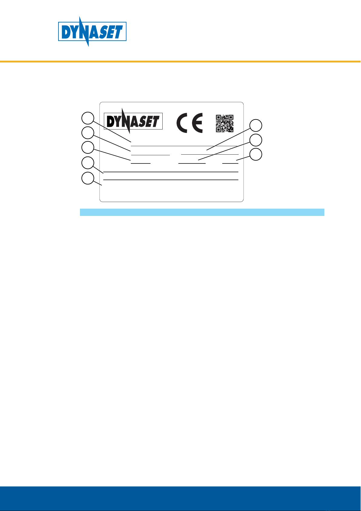
Dynaset HPW DUST 200 User manual

HPW DUST 200
HPW DUST 200 DOUBLE DUST
HPW DUST 220 DOUBLE DUST
HPW DUST 180 DOUBLE DUST
HPW DUST 130 DOUBLE DUST
rev 1.0
HIGH PRESSURE DUST SUPPRESSION
USER MANUAL
Download PDF version from www.Dynaset.com/manuals Keycode: F9KMKS


Dynaset Oy | Menotie 3, FI-33470 Ylöjärvi, Finland | tel: +358 3 3488 200 | inf[email protected] | www.dynaset.com 3
Congratulations!
You have just purchased DYNASET hydraulic equipment!
The equipment allows you to maximize the productivity and
efficiency of your mobile machine. Read this User Manual
before using your new equipment. It contains important
information that will help you to take the full advance of the
technical features avaible in your equipment.
Please contact us for any feedback you might have on our
products. Your feedback is important to us for improving our
products and customer service.
We are constantly developing and releasing new innovations.
Please visit on our website and social media channels for the
latest news and updates.
www.dynaset.com
info@dynaset.com
www.facebook.com/dynaset
www.youtube.com/dynasetoy
www.twitter.com/Dynaset_ofcl
www.instagram.com/dynaset_official
Subscribe to our newsletter. Follow the QR
code!

HIGH PRESSURE DUST SUPPRESSION
TABLE OF CONTENTS
1. GENERAL 7
1.1. PRODUCT INFORMATION 7
1.2. PRODUCT IDENTIFICATION 8
1.3. TYPE PLATE 9
1.4. HPWDUST SYSTEM LINEUP 9
1.5. MAIN COMPONENTS OF HPWDUST SYSTEM 10
2. SAFETY 11
2.1. SAFETY PRECAUTIONS 11
2.2. OPERATING SAFETY 12
2.3. MAINTENANCE SAFETY 12
2.4. WARNING LABELS 13
3. OPERATING PRINCIPLES 15
3.1. OPERATING DESCRIPTION 15
3.2. HPWDUST 16
3.3. HPWDUST DOUBLE DUST 17
3.3.1. DUAL WATER CIRCUIT DWC 17
3.3.2. SINGLE WATER CIRCUIT SWC 18
4. INSTALLATION OF THE HPW-DUST SYSTEM 19
4.1. INSTALLATION TO A HYDRAULIC LINE 19
4.2. HYDRAULIC FLUIDS 21
4.3. POSITIONING THE HPWDUST COMPONENTS 21
4.3.1. POSITIONING THE HPWPUMP 21
4.3.2. POSITIONING THE DUST SUPPRESSION NOZZLES 22
4.3.3. POSITIONING THE WATER SOLENOID VALVE 23
4.4. INSTALLATION TO A WATER LINE 24
4.5. CONTROL WIRING 25
4.5.1. HPWPUMP/DUST SUPPRESSION ONOFF SWITCH 25
4.5.2. HIGH POWER WATER SOLENOID VALVE PUSHBUTTON 25
4.5.3. HIGH POWER WATER MODE IN SIGLE WATER CIRCUIT 26

HIGH PRESSURE DUST SUPPRESSION
TABLE OF CONTENTS
5. OPERATION 29
5.1. BEFORE OPERATING THE HPWDUST SYSTEM 29
5.2. STARTING AND STOPPING THE HPWDUST SYSTEM 29
5.3. HIGH POWER DUST SUPPRESSION 29
5.4. WORKING IN COLD TEMPERATURES 30
6. MAINTENANCE 31
6.1. MAINTENANCE INTERVAL 31
6.2. HYDRAULIC FLUIDS 32
6.3. CLEAN THE HPWDUST SYSTEM 32
6.4. CLEAN WATER FILTER 33
6.5. TROUBLESHOOTING 33
7. MANUFACTURER’S LIMITED WARRANTY 35
8. PRODUCT DISPOSAL 37
9. DECLARATION OF CONFORMITY 39
10. TECHNICAL SPECIFICATIONS 41

Dynaset Oy | Menotie 3, 33470 Ylöjärvi | puh. 03 3488 200 | info@dynaset.com | www.dynaset.com
HIGH PRESSURE DUST SUPPRESSION
TABLE OF PICTURES
Picture 1: Type plate 9
Picture 2: Main components of HPW-DUST system 10
Picture 3: Operating principles 15
Picture 4: Basic HPW-DUST installation diagram 16
Picture 5: Dual Water Circuit installation diagram 17
Picture 6: Single Water Circuit installation diagram 18
Picture 7: Example installation to open centre hydraulic system 19
Picture 8: Example installation to closed centre hydraulic system without PC-SAE 20
Picture 9: Positioning the HPW-pump 21
Picture 10: Positioning the dust suppression nozzles 22
Picture 11: Positioning the water solenoid valve 23
Picture 12: Installation to a water line 24
Picture 13: HPW-pump’s on-o switch 25
Picture 14: High power water solenoid valve push-button 25
Picture 15: High power water mode in single water circuit 26
Picture 16: Before operating the HPW-DUST system 29
Picture 17: Location of leakage detectors in HPW 31
Picture 18: Clean water lter 33

7
Dynaset Oy | Menotie 3, FI-33470 Ylöjärvi, Finland | tel: +358 3 3488 200 | inf[email protected] | www.dynaset.com
HIGH PRESSURE DUST SUPPRESSION
GENERAL
7
1. GENERAL
This manual contains general information about assembly, installation, operation
and maintenance of DYNASET HPW DUST High Pressure Dust Suppression System.
ATTENTION!
Read this user manual before installation, use or maintenance of the HPW
DUST system to ensure proper handling, operation and maintenance right
from the beginning. Pay attention to warnings and safety instructions.
READ CHAPTER ”2. SAFETY” for more information.
1.1. PRODUCT INFORMATION
DYNASET HPW-DUST Dust Suppression System converts the hydraulic power of
a mobile machine into a high pressure water mist. It is integrated onto the base
machine’s attachment head or where the dust suppression is needed to get the
maximum effect. The system creates an effective high pressure dust control with
optimal water consumption. High pressure water uses less water and gives better
dust suppression performances with a smaller water drop size than traditional low
pressure dust suppression systems.
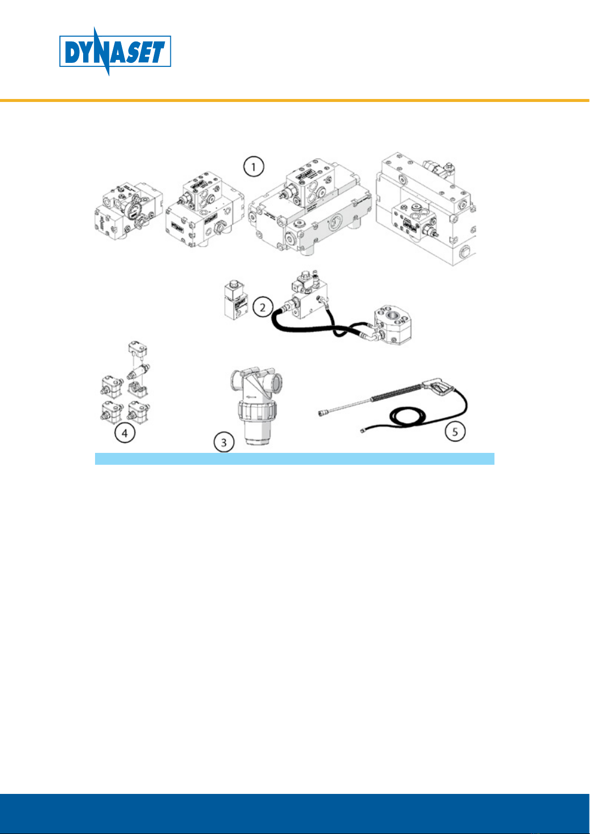
HPW-DUST has different nozzle and pump configurations to fit all vehicles and
dust suppression applications. The system can also be equipped with a Double
Dust boosting system that multiplies the dust suppression power. The HPW-DUST
also comes with a power washing pistol for all power washing applications.

8Dynaset Oy | Menotie 3, FI-33470 Ylöjärvi, Finland | tel: +358 3 3488 200 | inf[email protected] | www.dynaset.com
HIGH PRESSURE DUST SUPPRESSION
GENERAL
8
1.2. PRODUCT IDENTIFICATION
1. Product group HPW-DUST High Pressure Dust Suppression System.
2. WATER PUMP (Listed below)
HPW 200
Maximum pressure: 200 bar
Maximum flow: 30 l/min
Hydraulic pressure max: 210 bar
Hydraulic flow max: 40 l/min
HPW 220
Maximum pressure: 220 bar
Maximum flow: 50 l/min
Hydraulic pressure max: 210 bar
Hydraulic flow required: 70 l/min
HPW 180
Maximum pressure: 180 bar
Maximum flow: 90 l/min
Hydraulic pressure max: 210 bar
Hydraulic flow max: 115 l/min
HPW 130
Maximum pressure: 130 bar
Maximum flow: 180 l/min
Hydraulic pressure max: 250 bar
Hydraulic flow max: 140 l/min
3. DOUBLE DUST (optional)
Provides dual stage power output. Lower stage is typically set to one third from
higher power stage. Lower stage reduces water consumption and higher stage
gives extra boost for dust suppression when needed.

9
Dynaset Oy | Menotie 3, FI-33470 Ylöjärvi, Finland | tel: +358 3 3488 200 | inf[email protected] | www.dynaset.com
HIGH PRESSURE DUST SUPPRESSION
GENERAL
9
1.3. TYPE PLATE
Type plate is located on the HPW pump.
Type
Nr
Oil Flow
Manufacturer:
Dynaset Oy
33470 Ylöjärvi Finland
www.dynaset.com
Tel +358 3 3488200
YearPressure
Code
Made in Finland
POWERED BY HYDRAULICS
HPW 200/30 - 45 ST
45 l/min
12345-6789Dxxxxxxxxx
210 bar 11/15
Qw = 30 l/min
Pw = 200 bar
1
2
3
4
7
8
5
6
Picture 1: Type plate
The products type plate shows the following information.
1. Product identification key
2. Product code
3. Serial number
4. Maximum hydraulic flow
5. Maximum hydraulic pressure
6. Production month / year
7. Output water flow
rate and pressure.
8. Manufacturer’s contact
information
1.4. HPW-DUST SYSTEM LINE-UP
• HPW DUST 200
• HPW DUST 200 DOUBLE DUST
• HPW DUST 220 DOUBLE DUST
• HPW DUST 180 DOUBLE DUST
• HPW DUST 130 DOUBLE DUST
For specific characteristics of the HPW-DUST System line up READ CHAPTER “10.
TECHNICAL SPECIFICATIONS”

10 Dynaset Oy | Menotie 3, FI-33470 Ylöjärvi, Finland | tel: +358 3 3488 200 | inf[email protected] | www.dynaset.com
HIGH PRESSURE DUST SUPPRESSION
GENERAL
10
1.5. MAIN COMPONENTS OF HPW-DUST SYSTEM
Picture 2: Main components of HPW-DUST system
1. HPW-Pump
2. Control valves
3. Water intake filter
4. High pressure water nozzles
5. Spray gun with 10m hose

Dynaset Oy | Menotie 3, FI-33470 Ylöjärvi, Finland | tel: +358 3 3488 200 | inf[email protected] | www.dynaset.com 11
HIGH PRESSURE DUST SUPPRESSION
SAFETY
2. SAFETY
2.1. SAFETY PRECAUTIONS
ATTENTION!
Operators and maintenance personnel must always comply with local
safety regulations and precautions in order to close out the possibility of
damages and accidents.
The pressure in both hydraulic oil and water circuits of HPW-DUST system is
considerably high. Keep the condition of your equipment and hydraulic system
under constant observation.
WARNING
HIGH PRESSURE WATER AND OIL!
Can cause severe injuries.
Always wear appropriate clothing
and safety equipment.
Couplings, valves and hoses need to be kept tight and clean to avoid possible
leakages. Leaks in the hydraulic system must be repaired immediately to avoid
injuries caused by high pressure blowouts.
In order to avoid accidents, it is not allowed to clean or inspect HPW-DUST system
when hydraulic fluid circuit is pressurized. Prior to any cleaning, inspection and
service, hydraulic system of your base machine must be stopped and all hydraulic
fluid circuits must be depressurized.
Prevent nozzles, water circuit and pipeline from freezing. Draining and air flushing
of the water circuit have to performed before ambient temperature reaches 0°C
or lower.

Dynaset Oy | Menotie 3, FI-33470 Ylöjärvi, Finland | tel: +358 3 3488 200 | inf[email protected] | www.dynaset.com
12
HIGH PRESSURE DUST SUPPRESSION
SAFETY
2.2. OPERATING SAFETY
When operating the HPW-DUST system, beware of the unit parts warmed by hot
hydraulic oil.
WARNING
RISK OF BURNS!
The unit parts and hydraulic oil can
be hotter than 80 °C!
Wear personal safety equipment!
Never aim high pressure water at a person.
WARNING
HIGH PRESSURE WATER!
Never aim high pressure water at a person.
This can cause severe injuries.
ATTENTION!
Do not exceed the maximum pressure, temperature or load.
2.3. MAINTENANCE SAFETY
ATTENTION
Installation and service of hydraulic equipment must be performed by
qualified and experienced personnel only.

Dynaset Oy | Menotie 3, FI-33470 Ylöjärvi, Finland | tel: +358 3 3488 200 | inf[email protected] | www.dynaset.com 13
HIGH PRESSURE DUST SUPPRESSION
SAFETY
NOTE!
When carrying out any maintenance to HPW-DUST system keep the
components of the system clean. This is to ensure safe, reliable and longlife
operation of your equipment.
Hydraulic system of the base machine should be maintained according to the
service program.
2.4. WARNING LABELS
Product recipient is obligated to place warning labels on the DYNASET product.
Attach labels to visible and appropriate place onto or close to DYNASET product
where it’s easily seen. Clean surface with solvent detergent before attaching labels.
BEWARE OF HOT
SURFACE.
USE EAR PROTECTION
AND SAFETY
GOGGLES.
READ OPERA
TING
INSTRUCTIONS.
BEWARE OF HIGH
PRESSURE
SPLATTERS.
KEEP FROM
FREEZING.

Dynaset Oy | Menotie 3, FI-33470 Ylöjärvi, Finland | tel: +358 3 3488 200 | inf[email protected] | www.dynaset.com
14
HIGH PRESSURE DUST SUPPRESSION
SAFETY

Dynaset Oy | Menotie 3, FI-33470 Ylöjärvi, Finland | tel: +358 3 3488 200 | inf[email protected] | www.dynaset.com 15
HIGH PRESSURE DUST SUPPRESSION
OPERATING PRINCIPLES
3. OPERATING PRINCIPLES
3.1. OPERATING DESCRIPTION
1. The HPW-DUST Dust Suppression System uses the power from the base
machine’s hydraulic system.
2. The HPW-DUST patented piston-to-piston pump converts the hydraulic power
into high pressure water.
3. High pressure water is pumped to the carefully designed dust suppression
nozzles which create the high pressure water mist. High pressure water mist
increases the mass of the dust particles and forces the dust to fall onto the
ground.
Picture 3: Operating principles

Dynaset Oy | Menotie 3, FI-33470 Ylöjärvi, Finland | tel: +358 3 3488 200 | inf[email protected] | www.dynaset.com
16
HIGH PRESSURE DUST SUPPRESSION
OPERATING PRINCIPLES
3.2. HPW-DUST
DYNASET HPW-DUST System provides continuous dust suppression with 2 pairs
of nozzles. Dust suppression is controlled with hydraulic solenoid valve of the
HPW-Pump.
Picture 4: Basic HPW-DUST installation diagram
1. Basic nozzles

Dynaset Oy | Menotie 3, FI-33470 Ylöjärvi, Finland | tel: +358 3 3488 200 | inf[email protected] | www.dynaset.com 17
HIGH PRESSURE DUST SUPPRESSION
OPERATING PRINCIPLES
3.3. HPW-DUST DOUBLE DUST
DYNASETHPW-DUSTDoubleDustboostingSystemmultipliesthedustsuppression
power. Double Dust is implemented in two different ways:
3.3.1. DUAL WATER CIRCUIT (DWC)
Dual Water Circuit comes with basic and high power nozzle pairs. Basic pair of
nozzles provide continuous dust suppression. High power pair is controlled by
water solenoid valve and can be used when suppression boost is needed.
Picture 5: Dual Water Circuit installation diagram
1. Basic nozzles
2. High power nozzles
3. High power water
solenoid valve

Dynaset Oy | Menotie 3, FI-33470 Ylöjärvi, Finland | tel: +358 3 3488 200 | inf[email protected] | www.dynaset.com
18
HIGH PRESSURE DUST SUPPRESSION
OPERATING PRINCIPLES
3.3.2. SINGLE WATER CIRCUIT (SWC)
Single Water Circuit comes with one type of nozzles. The output water flow and
pressure is controlled with hydraulic valve kit. Hydraulic valve provides two
separate hydraulic flows to the HPW-pump. Lower hydraulic flow to the continuous
dust suppression and higher hydraulic flow to the high power dust suppression.
Picture 6: Single Water Circuit installation diagram
1. Basic nozzles 2. Hydraulic valve

Dynaset Oy | Menotie 3, FI-33470 Ylöjärvi, Finland | tel: +358 3 3488 200 | inf[email protected] | www.dynaset.com 19
HIGH PRESSURE DUST SUPPRESSION
INSTALLATION
4. INSTALLATION OF THE HPW-DUST SYSTEM
4.1. INSTALLATION TO A HYDRAULIC LINE
The HPW-DUST system is installed into the base machine’s existing hydraulic line.
It is recommended to use DYNASET HPW-VR-PA -pump in the installation.
In the picture 7is an example of installing the HPW-DUST system into a
open centre hydraulic line.
Picture 7: Example installation to open centre hydraulic system
1. DYNASET HPW-VR-PA -pump
2. Base machines variable
displacement pump
3. Open centre directional
control valves
4. Oil cooler
5. Oil filter
6. Oil tank
7. Solenoid valve
8. DYNASET PC-SAE pressure
compensator

Dynaset Oy | Menotie 3, FI-33470 Ylöjärvi, Finland | tel: +358 3 3488 200 | inf[email protected] | www.dynaset.com
20
HIGH PRESSURE DUST SUPPRESSION
INSTALLATION
In the picture 8is an example of installing the HPW-DUST system into a closed
centre hydraulic line without PC-SAE.
Picture 8: Example installation to closed centre hydraulic system without
PC-SAE
1. DYNASET HPW pump
2. Base machines variable
displacement pump
3. Closed centre directional
control valves
4. Oil cooler
5. Oil filter
6. Oil tank
7. Solenoid valve
8. DYNASET Shuttle valve
Ensure that the hydraulic flow of the base machine is sufficient to run the HPW-
DUST system. At least the nominal hydraulic flow must be available to get the
maximum dust suppression power.
This manual suits for next models
3
Table of contents