INSTRUCTIONS: REPLACEMENT/SAFETY GEAR; Code: DYN 32.03.00
Date: 29/06/2016 Revision: 00
3
1 BACKGROUND
Dynatech equipment is assembled according to customer specifications, so handling is not necessary. If the
shoe needs to be replaced, Dynatech offers customers this manual for the proper conduct of this work.
However, under no circumstances will Dynatech be held responsible for any error or deterioration in the
equipment following handling by non-Dynatech personnel, even if they follow the manual instructions.
- Dynatech or your nearest dealer must be contacted for the replacement shoes, according to the
necessary guide rail width.
- The following details must be provided:
oSafety gear model
oNew guide rail width (to select replacement shoe)
oSeries number
2 SHOE REPLACEMENT ACCORDING TO SAFETY GEAR MODEL
2.1 SERIES ASG-XXX UD/ ASG-XXX
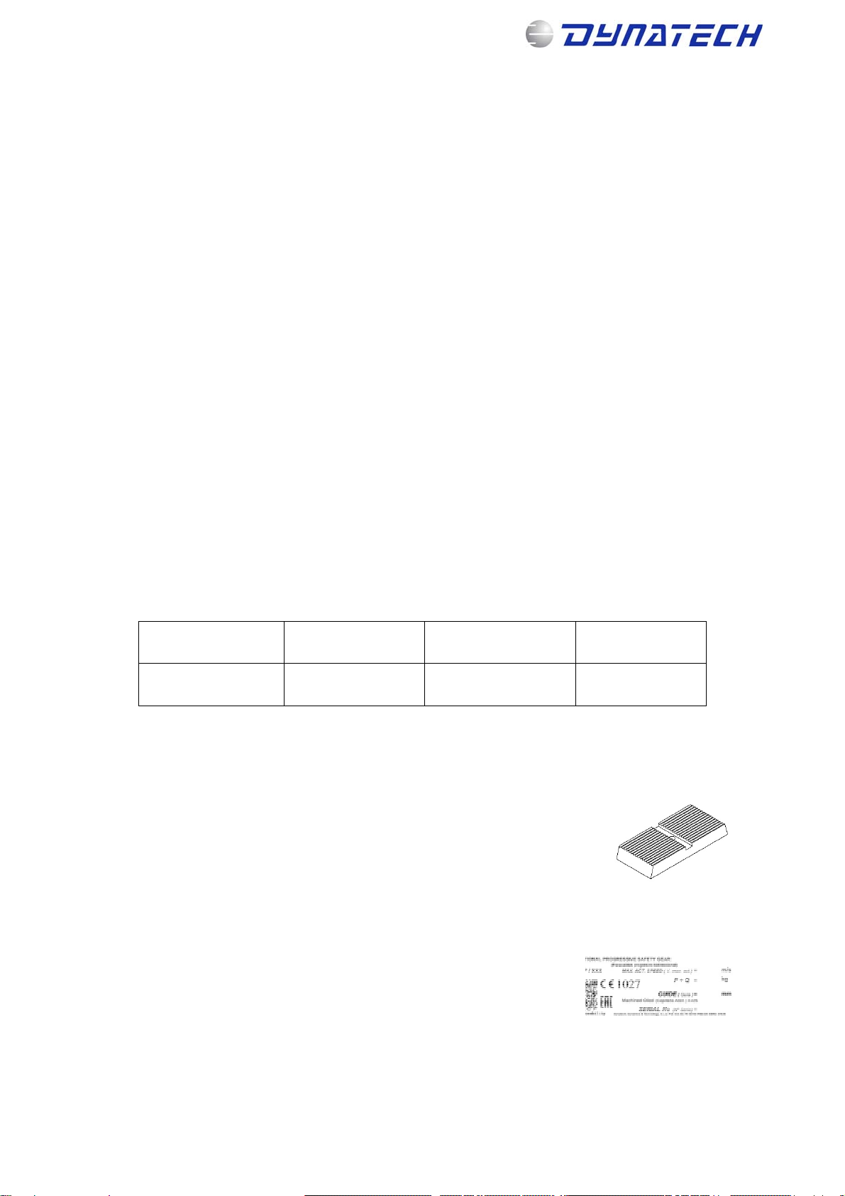
There are three safety gear types of this model, depending on the thickness of the shoe assembled. The
safety gear types refer to the guide rail centre position in relation to the frame attachment holes, which are in
accordance with the measurement recommended in the safety gear (DYN.32) usage and maintenance
instructions. Thus, the gap between the shoe and guide rail established by Dynatech is observed.
TYPE A B C
THICKNESS (mm) 7-8-9-10 11-12-13 14-15-16
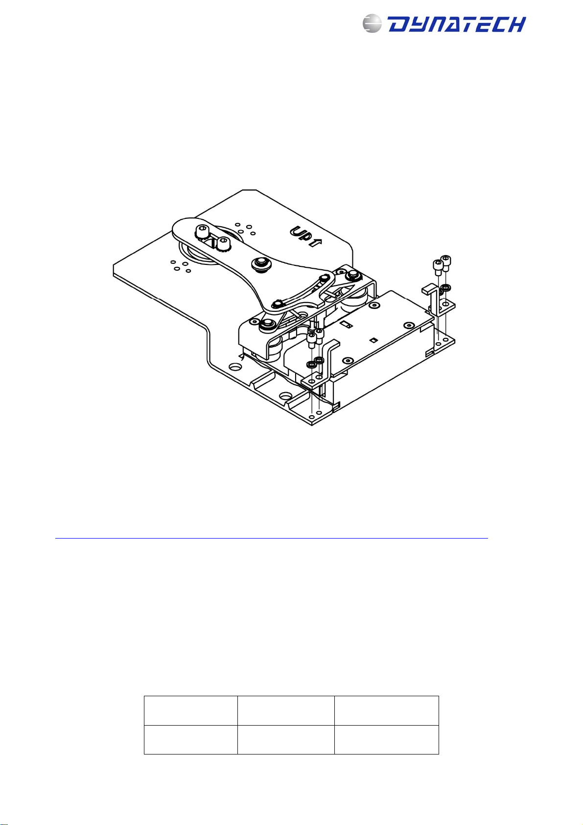
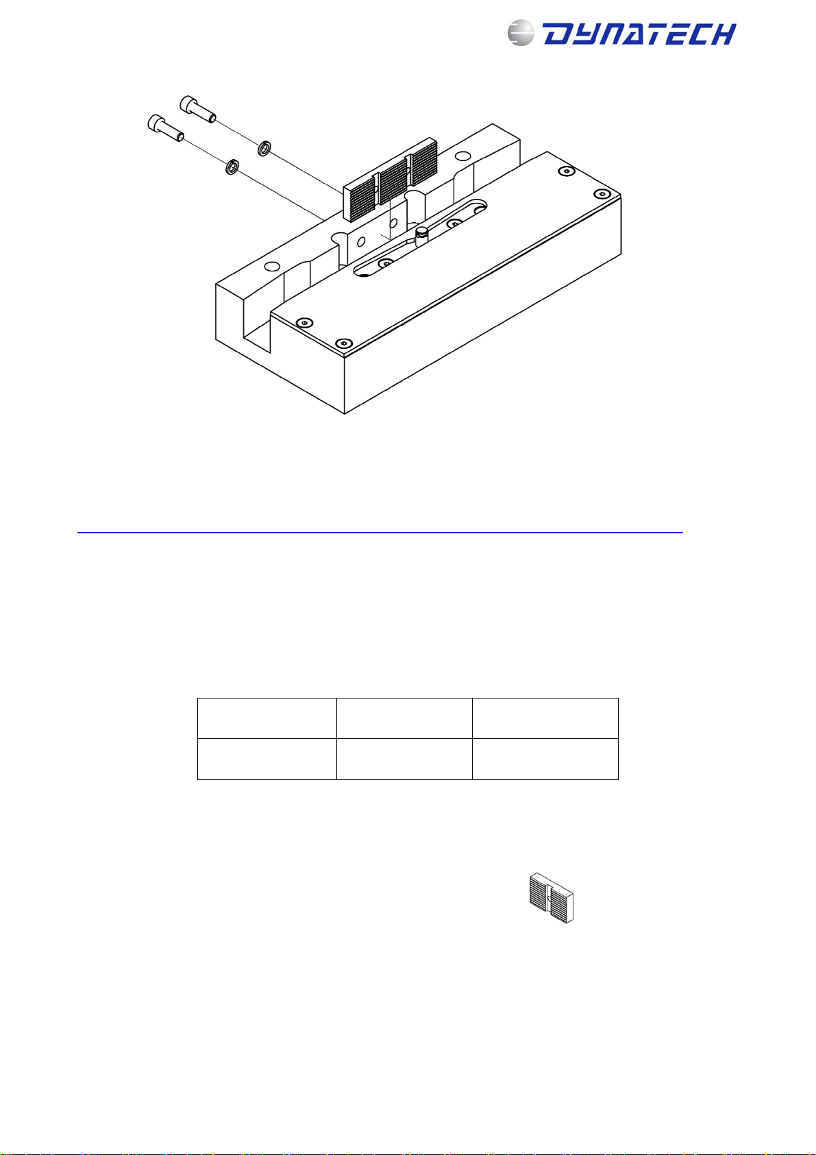
The steps for replacing the shoe to change the thickness are as follows:
1. The following must be available:
- Replacement shoe: with the new guide rail thickness.
- Stickers with the new guide rail thickness.