Dynatech PR-2500-UD Series Specification sheet

PARACAÍDAS PROGRESIVO DYNATECH/
DYNATECH PROGRESSIVE SAFETY GEAR/
PARACHUTE À PRISE AMORTIE DYNATECH/
BREMSFANGVORRICHTUNG DYNATECH/
PR-2500-UD
INSTRUCCIONES DE USO Y MANUTENCIÓN/
INSTRUCTIONS FOR USE AND MAINTENANCE/
INSTRUCTIONS D’USAGE ET ENTRETIEN/
GEBRAUCHS- UND WARTUNGSANLEITUNG/

INSTRUCTIONS : PR-2500-UD Cod : DYN 05.01.08
Date: 15/04/2016 Revision: 08
1
REVISION
08
DATE
15/04/2016
PRODUCED BY / APPROVED BY
P. Hernandez/J. Marco
SECTION
DESCRIPTION
Effective date of
change
2.1
The safety gear identification label is updated according to the
2014/33/EU Directive
20/04/2016
-
The certificate number according to the UNE-EN 81-20, UNE-EN
81-50 and 2014/33/EU Directive is included
Not applicable
6
The general plan is updated
Not applicable
REVISION
07
DATE
19/02/2015
PRODUCED BY / APPROVED BY
J. Marco/O. Lacámara
SECTION
DESCRIPTION
Effective date of
change
3.3.1
Pictures updated
Not applicable
REVISION
06
DATE
30/05/2014
PRODUCED BY / APPROVED BY
J. Marco/O. Lacámara
SECTION
DESCRIPTION
Effective date of
change
-
The entire manual was reviewed
Not applicable


INSTRUCTIONS : PR-2500-UD Cod : DYN 05.01.08
Date: 15/04/2016 Revision: 08
2
INSTRUCTIONS FOR USE AND MAINTENANCE
_____________________________________________________
1GENERAL INSTRUCTIONS .................................................................................................................................... 3
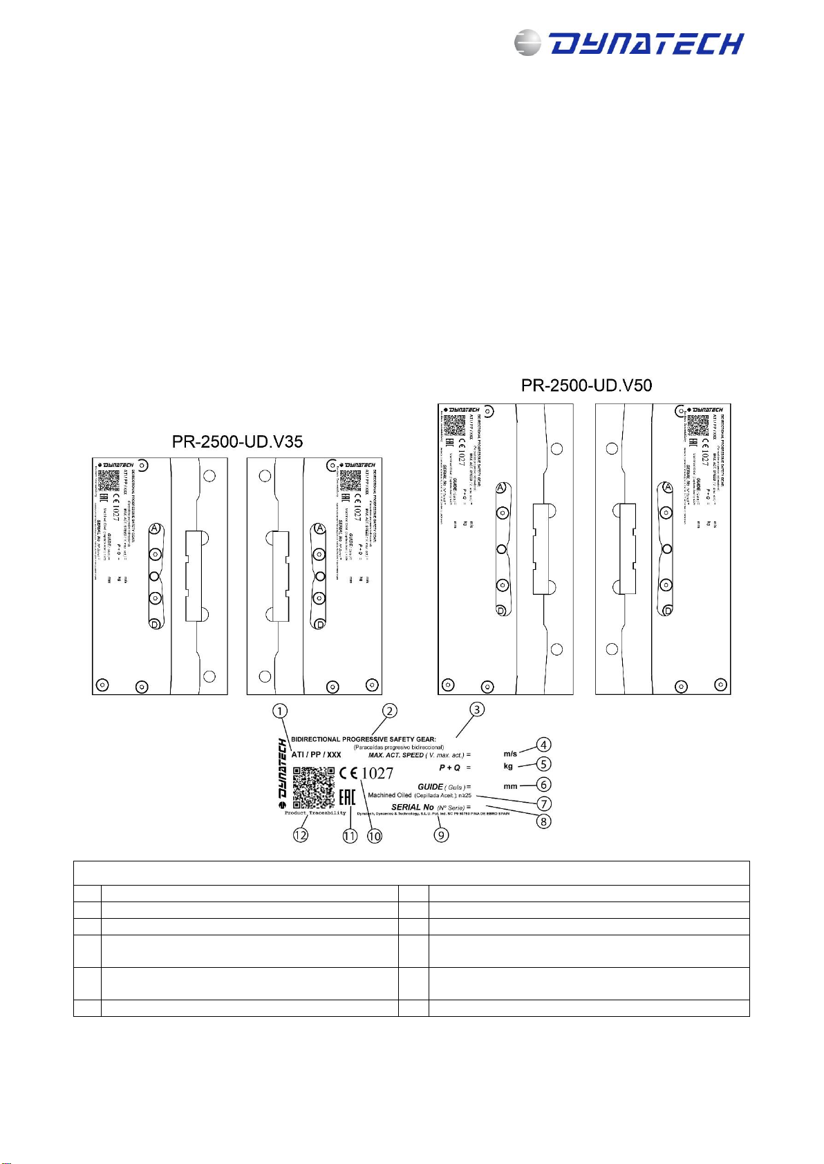
2SAFETY GEAR IDENTIFICATION AND CHARACTERISATION ................................................................................... 3
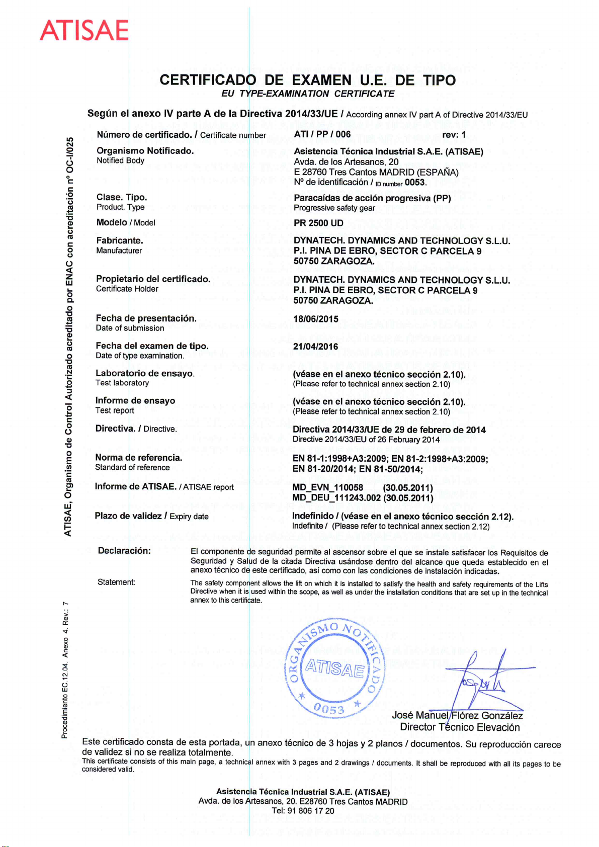
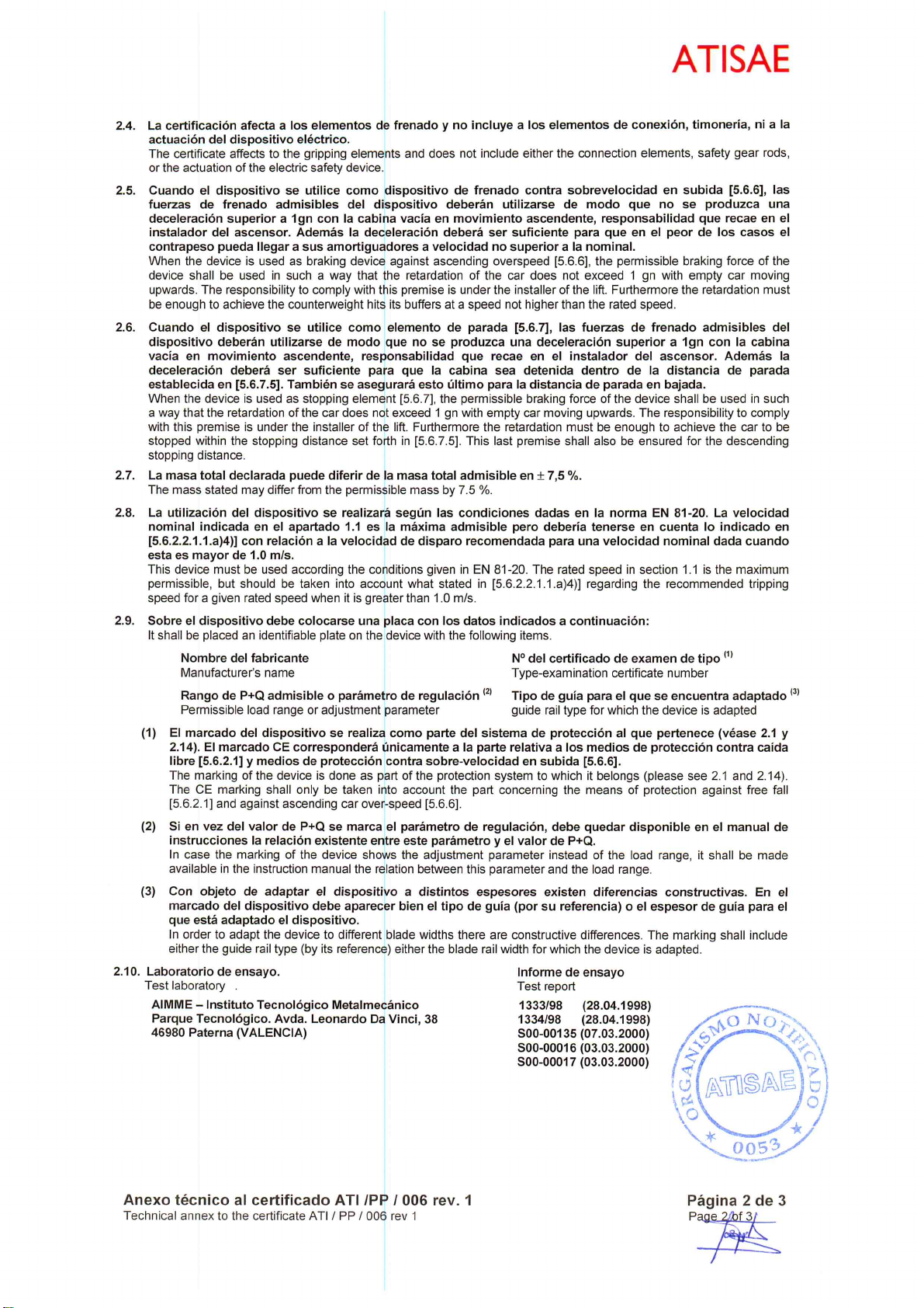
2.1 IDENTIFICATION .................................................................................................................................................. 3
2.2 SAFETY GEAR’S FEATURES AND USE .................................................................................................................... 4
2.3 RANGE OF USE..................................................................................................................................................... 4
3INSTALLATION AND ADJUSTMENT ...................................................................................................................... 4
3.1 ASSEMBLY ON THE FRAME .................................................................................................................................. 4
3.2 SAFETY GEAR ADJUSTMENT ................................................................................................................................ 6
3.3 COUPLING THE DRIVING BAR .............................................................................................................................. 7
3.3.1 USING DYNATECH’S T-2 DRIVING BAR ........................................................................................................ 7
3.3.2 USING DYNATECH’S T-3 DRIVING BAR ........................................................................................................ 8
4INSPECTIONS AND MAINTENANCE...................................................................................................................... 8
4.1 CHECKING THE SAFETY GEARS ............................................................................................................................ 8
4.2 PRECAUTIONS ..................................................................................................................................................... 9
4.3 MAINTENANCE.................................................................................................................................................... 9
4.3.1 LIST OF MAINTENANCE OPERATIONS ......................................................................................................... 9
4.3.2 CORROSION................................................................................................................................................. 9
4.4 STORAGE AND SERVICE LIFE ................................................................................................................................ 9
5UCM...................................................................................................................................................................10
5.1 UCM SYSTEM’S PRELIMINARY DESIGN. ............................................................................................................. 10
5.2 SAFETY GEAR BRAKING DISTANCE CALCULATION ............................................................................................. 10
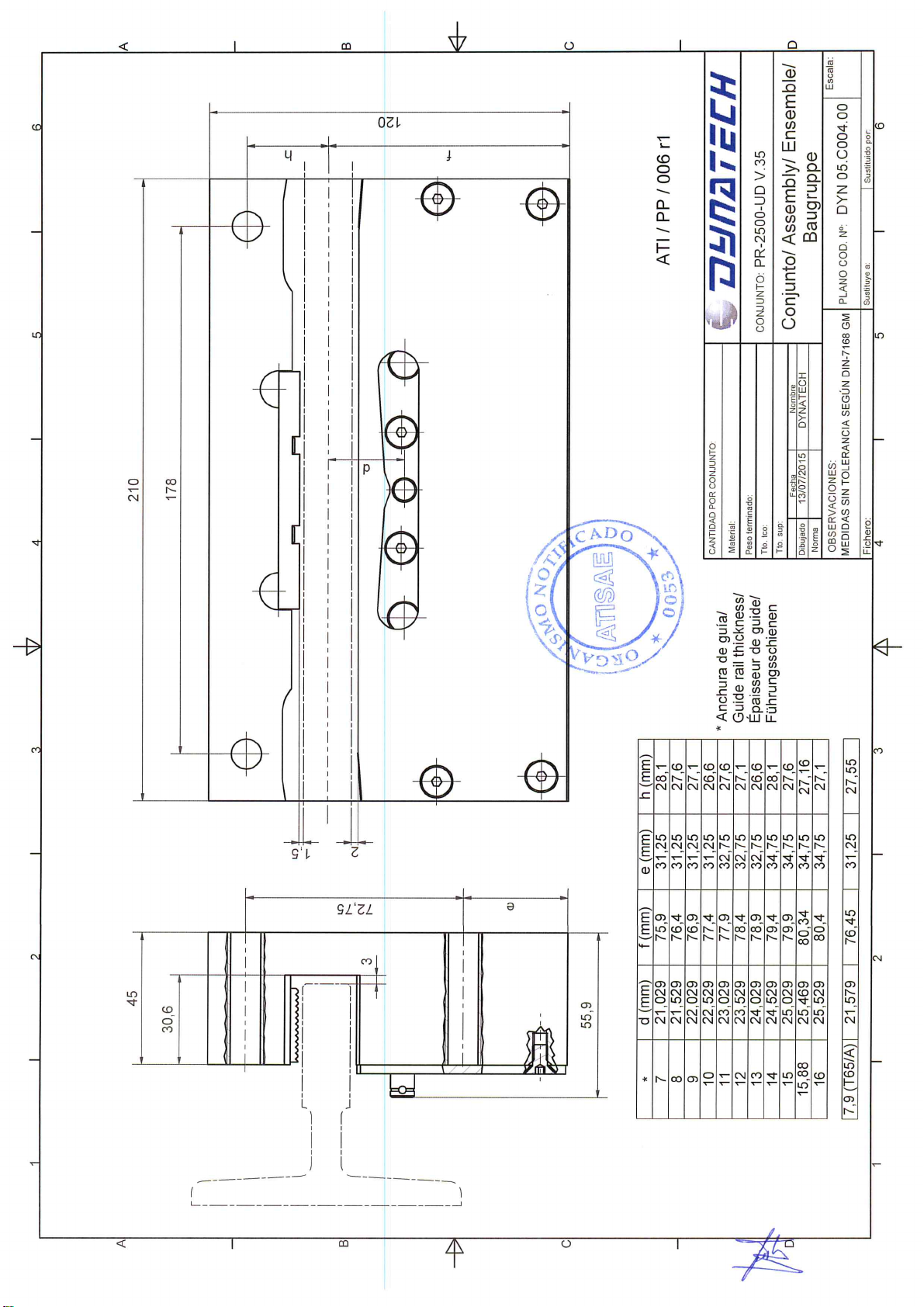
6GENERAL DRAWING ...........................................................................................................................................10
_____________________________________________________

INSTRUCTIONS : PR-2500-UD Cod : DYN 05.01.08
Date: 15/04/2016 Revision: 08
3
1 GENERAL INSTRUCTIONS
Each pair of safety gears supplied is factory tared according to the required conditions of use: Total mass
(P+Q) and guide rails’ thickness. These features are indelibly displayed, along with the standardisation
password and serial number; on the protection plates on top of the safety gear boxes (see section 2.1).
It is strictly forbidden:
a) To combine and assemble safety gear boxes with different serial numbers.
b) To use a pair of safety gears for installations with characteristics different from those indicated on that
pair of safety gears’ protection plates.
c) To handle any of the safety gear’s components.
DYNATECH DYNAMICS & TECHNOLOGY, S.L. cannot be held responsible for the damage caused due to
the non-observance of any of these general instructions.
2 SAFETY GEAR IDENTIFICATION AND CHARACTERISATION
2.1 IDENTIFICATION
Figure 1: Safety gear identification
SAFETY GEAR IDENTIFICATION LABEL
1
Nº de certificado de examen U.E.de tipo
7
Guide rail type
2
Safety gear type
8
Safety gear serial number
3
Safety gear model
9
Dynatech address
4
Safety gears’maximum tripping speed (m/s)
10
Quality assurance CE marking and notified body
number
5
Total load (Kg)
11
Marking for market access to member states of the
Customs Union
6
Guide rail thickness (mm)
12
QR product traceability code

INSTRUCTIONS : PR-2500-UD Cod : DYN 05.01.08
Date: 15/04/2016 Revision: 08
4
2.2 SAFETY GEAR’S FEATURES AND USE
This safety gear may be used with guide rails that have braking surfaces equal to or greater than 25 mm,
provided that the following requirements are complied with:
a) The guide rails to be used should be cold drawn or machined. Allowable tolerances for guide rail
thickness should be within the limits set by the standard: ISO 7495:197.
b) For lubricated guide rails, the recommended lubricating oil is the type used for machines according to
ISO VG 150, although other viscosities within the margins established in ISO-VG may be accepted.
c) This safety gear can be used up to a maximum tripping speed of 2.5 m/s.
d) Allowable guide rail thicknesses: 7 –16 mm.
e) Guide rail’s braking surface equal to or more than 25mm.
This safety gear may be used with guide rails with braking surfaces equal to 20 mm (for example T 65 A),
provided that the following requirements are complied with:
a) The guide rails to be used should be cold drawn. Allowable tolerances for guide rail thickness should
be within the limits set by the standard: ISO 7495:197.
b) For lubricated guide rails, the recommended lubricating oil is the type used for machines according
to ISO VG 150, although other viscosities within the margins established in ISO-VG may be
accepted.
c) This safety gear can be used up to a maximum tripping speed of 1.5 m/s.
d) The guide rail’s braking surface is equal to 20 mm.
2.3 RANGE OF USE
Please find below the standard P+Q table. The rated values are displayed in bold in the middle row. The safety
gears, when supplied, are set to the default rated value; however, they can be used in installations with P+Q
values within the upper and lower limits.
For guide rails with braking surfaces equal to or greater than 25 mm
Lower limit r
567
658
764
859
963
1060
1178
1317
1454
1627
1808
P+Q (Kg)
613
711
826
929
1041
1146
1274
1424
1572
1759
1955
Upper limit
659
764
888
999
1119
1232
1370
1531
1690
1891
2102
For guide rails with braking surfaces equal to 20 mm (for example, T 65 A)
Lower limit
621
P+Q (Kg)
671
Upper limit
721
Loads may be duplicated through configuration of this tandem safety gear. See Manual DYN 37/8 –Extendible
T25UD/T25 Tandem safety gear for further information.
3 INSTALLATION AND ADJUSTMENT
3.1 ASSEMBLY ON THE FRAME
The holes should be made on the frame’s uprights to secure the safety gear, according to the dimensions and
position displayed in the safety gear drawings attached (DYN 05.C001.01 / DYN 05.C002.01), ensuring that
the guide rail’s axis is centred with the frame.

INSTRUCTIONS : PR-2500-UD Cod : DYN 05.01.08
Date: 15/04/2016 Revision: 08
5
To secure the safety gear onto the frame, we recommend a 79.09 Nm tightening torque for grade 8.8 M12
bolts, and of 111 Nm for grade 10.9 bolts.
⚠Safety gear position:
a) The safety gears should be assembled in the position displayed in Figure 4
b) The roller for upwards jamming is indicated with letter “A”. That is to say, roller “A” should be on the
upper part of the safety gear.
c) The roller for downwards jamming is indicated with letter “D”. That is to say, roller “D” should be on
the lower part of the safety gear.
Figure 4: Direction of assembly
Figure 2: Assembling safety gear onto the frame (1)
Figure 3: Assembling safety gear onto the frame (2)

INSTRUCTIONS : PR-2500-UD Cod : DYN 05.01.08
Date: 15/04/2016 Revision: 08
6
Figure 5: Roller position
Figure 6: Roller position on inverted guide rails
During assembly, the safety gear should be perfectly aligned with the guide rails, both vertically and
horizontally. Improper assembly may cause the safety gear to function incorrectly.
Figure 7: Improper assembly
3.2 SAFETY GEAR ADJUSTMENT
The guide rail's position in the block should be adjusted as follows: The side of the guide rail 1.5 mm from the
brake shoe; the head of the guide rail 3 mm from the back of the groove (see drawing DYN 05.C001.01 / DYN
05.C002.01).
⚠In order to avoid problems with the installation’s normal operation, it is very important that the person
carrying out the installation rigorously observes the distances mentioned in this item.
⚠It should be checked that the safety gear is placed so that the rollers for downwards jamming, marked
with the letter “D”, are on the bottom part of the safety gear, as is shown in item 3.1.

INSTRUCTIONS : PR-2500-UD Cod : DYN 05.01.08
Date: 15/04/2016 Revision: 08
7
Total clearance = 3.5 mm
Total clearance = 5 mm
Figure 8 Safety gear adjustment in relation to the guide rail
3.3 COUPLING THE DRIVING BAR
It is the responsibility of the person who installs the safety gear to properly position the driving bar in relation
to the safety gear, as well as to properly synchronise the safety gears controlled by that driving bar. The driving
bar is properly positioned when the trolley’s pivot is in the protection plate’s central position.
Once it has been fitted and the safety gear’s roller’s trolleys have been attached to the driving bar’s tripping
bars, it should be checked that both trolleys operate simultaneously, controlled by the driving bar. This should
be checked in both directions, ascending and descending.
The overspeed governor should generate a minimum force that it should be twice the force to ensure the
synchronized performance of the safety gears.
⚠The Standard demands that the installation incorporate an AC-15 or DC-13 safety contact as defined in
EN 60947-5-1.
3.3.1 USING DYNATECH’S T-2 DRIVING BAR
The PR-2500-UD.V35 safety gear may be synchronised by assembling Dynatech’s T-2 driving bar. For more
information concerning T-2 driving bar assembly, please consult its manual: DYN06 –Instructions T-2.
⚠T-2 driving bars cannot be used with PR-2500-UD.V50 safety gears
⚠It is not recommended to exceed a maximum force of 1900 N is not recommended with the governor.
Figure 9: Safety gear synchronisation using the T-2 driving bar

INSTRUCTIONS : PR-2500-UD Cod : DYN 05.01.08
Date: 15/04/2016 Revision: 08
8
3.3.2 USING DYNATECH’S T-3 DRIVING BAR
PR-2500-UD.V35 and PR-2500-UD.V50 safety gears may be synchronised by assembling Dynatech’s T-3
driving bar. For more information concerning T-3 driving bar assembly, please consult its manual: DYN08 –
Instructions T-3.
⚠It is not recommended to exceed a maximum force of 1900 N is not recommended with the governor.
Figure 10: Safety gear synchronisation using the T-3 driving bar
4 INSPECTIONS AND MAINTENANCE
4.1 CHECKING THE SAFETY GEARS
For the safety gears to function correctly, their proper assembly and adjustment must be verified as well as
the sturdiness of the unit’s connection to the car and the guide rails, as is stated in the standard EN 81:1+A3.
It is recommended to follow the standard’s provisions for inspections and tests, both for commissioning and
regular testing.
The safety gear model’s behaviour curves may be requested from Dynatech based on its (P+Q) and the
installation’s rated load when tested dynamically with suspensions included.
The proper synchronisation of the safety gears may be checked by
verifying that the roller’s track is marked on both guide rails and that
they have a similar length, with the difference between the two sections
not being more than 4 cm.
The requirements for regular tests should not be greater than those for
commissioning. It is therefore recommended to always use the same
load (P/Q) and speed conditions. For better control, the maintenance
worker should have a safety gear operation record, where he or she
records the serial number and number of operations. A visual
inspection is sufficient to check that the installation has not been
damaged, see section 4.3.1.
It is not necessary to work on the safety gears due to their regular tests,
as long as their braking distance does not exceed double the distance
recorded from the first commissioning test.
After operating the safety gear in free fall, it is recommended to contact
Dynatech, or your nearest supplier, directly, who will indicate how to
proceed.
Figure 11: Braking track on guide
rail

INSTRUCTIONS : PR-2500-UD Cod : DYN 05.01.08
Date: 15/04/2016 Revision: 08
9
4.2 PRECAUTIONS
It is recommended to keep in mind the following items:
The factory protective covering should be removed from the guide rails. In addition, it should be
checked that there are no other objects, such as screws, brackets, etc. that may interfere with the
safety gear or its driving bar.
It should be visually checked that the safety gears are in working order, that they are not dirty or greasy
inside.
After any inspection or test where the safety gears were tripped, it should be checked that the safety
gears have not been damaged.
It is recommended to perform the tests near the car door to unload the car in order to facilitate
unjamming the safety gears.
The authorised personnel should always take the necessary precautions when tripping any of the
previously installed safety gears.
4.3 MAINTENANCE
Both for maintenance and inspection, the following maintenance operations should be performed after tripping
the safety gears.
4.3.1 LIST OF MAINTENANCE OPERATIONS
Safety gears:
Check that there is no interference between the shoe and the guide rail, nor between the rollers and
the guide rail.
Check the brackets and the clearance between the safety gears and the frame, readjust it if necessary.
Clean any remaining grease, shavings or dust inside the safety gear’s housing.
Check that there is no external element inside the safety gear’s housing.
Check that the rollers spin freely and are not damaged or worn.
Check that the connection between the rollers and the driving bar has not been damaged and spins
freely without being blocked.
Visually check that the safety gears are not damaged in general.
Check that the driving bar is in good condition and that the safety gears are correctly synchronised.
Check that the car’s floor does not have more than a 5% slope in comparison with its normal position.
Check that the governor’s attachment moves correctly and is in good condition.
Check that the safety electrical contact has been correctly assembled and is functioning properly.
Guide rails:
Clean and remove any type of dirt or dust from the guide rails.
Eliminate the marks or burrs caused by tripping the safety gears.
Apply a thin and even layer of lubricating oil, as indicated in item 2.2, section b) of this manual, on the
guide rails.
4.3.2 CORROSION.
All DYNATECH safety gears have anti-corrosion protection. However, it should be regularly checked that the
safety gear’s mobile elements are in perfect working condition; a jamming test will not be required, just a simple
verification that all the parts are moving freely, as well as a visual inspection of the general condition of the
surfaces.
These verifications should be done more regularly, as the maintenance worker considers necessary, when the
installation is in an especially corrosive environment.
4.4 STORAGE AND SERVICE LIFE
The safety gear should be stored in a cool, dry place. It should be protected from excessive lighting. It should
never be exposed to severe weather conditions.
Storage temperature: 5 - 40ºC
Storage humidity: 15 - 85% without condensation.
The safety gears’ packaging should be clean and dry, so that they can be clearly identified.

INSTRUCTIONS : PR-2500-UD Cod : DYN 05.01.08
Date: 15/04/2016 Revision: 08
10
It is not permitted to place constant or unbalanced loads on a package, which may cause the package to be
bent, or to allow products to be stacked one on top of the other. When stacking products or packages, the
storage height should take into account their load and stability.
If the criteria established for proper maintenance are observed, the safety gears may have the same service
life as the rest of the installation’s fixed elements provided that their proper functioning is ensured and
controlled. The element’s service life is not affected by grease, dust or dirt due to the shaft’s condition or to
environmental conditions differing from those stated in this manual.
5 UCM
5.1 UCM SYSTEM’S PRELIMINARY DESIGN.
According to UNE‐EN 81‐1:1998+A3:2009, lifts should be equipped with means for stopping uncontrolled car
movement (UCM). These means should detect UCM and stop the car. This stop must occur at a maximum
distance below 1 m (among other requirements).
The safety gears may be used as a braking device for stopping the uncontrolled movement.
The values for the safety gear’s braking distance may be calculated beforehand, but several installation
parameters must be taken into account. The more information that is known about the physical elements that
make up the system, the closer the theoretical value will be to the actual value.
These are theoretical values and may only be used in the system’s preliminary design. The installation’s
compliance with the standard requirements is pending.
5.2 SAFETY GEAR BRAKING DISTANCE CALCULATION
The detailed calculations can be found in the manual: DYN 62.04 –UCM. Braking distance.
6 GENERAL DRAWING

1
1
2
2
3
3
4
4
5
5
6
6
A A
B B
C C
D D
MEDIDAS SIN TOLERANCIA SEGÚN DIN-7168 GM PLANO COD. Nº:
Escala:
PR-2500-UD V.50
CONJUNTO:
Sustituye a: Sustituido por:
DYN 05.C001.01
OBSERVACIONES:
Material:
Peso terminado:
Tto. tco:
Tto. sup:
Fichero:
Fecha Nombre
Dibujado
Norma 20/07/2001 DYNATECH
CANTIDAD POR CONJUNTO:
45
30,6
258
178
72,75
e
120
3
1,5
3,5
h
f
55,7
Conjunto/ Assembly/
Ensemble/ Baugruppe
d
*d (mm) f (mm) e (mm) h (mm)
721,029 75,9 31,25 28,1
821,529 76,4 31,25 27,6
922,029 76,9 31,25 27,1
10 22,529 77,4 31,25 26,6
11 23,029 77,9 32,75 27,6
12 23,529 78,4 32,75 27,1
13 24,029 78,9 32,75 26,6
14 24,529 79,4 34,75 28,1
15 25,029 79,9 34,75 27,6
15,88 25,469 80,34 34,75 27,16
16 25,529 80,4 34,75 27,1
7,9 (T65/A) 21,579 76,45 31,25 27,55
* Anchura de guía/
Guide rail thickness/
Épaisseur de guide/
Führungsschienen
Historial de revisiones
Rev. Descripción Fecha Aprobado
01 Se actualiza tabla de Medidas 21/07/2015 Pilar H

1
1
2
2
3
3
4
4
5
5
6
6
A A
B B
C C
D D
MEDIDAS SIN TOLERANCIA SEGÚN DIN-7168 GM PLANO COD. Nº:
Conjunto/ Assembly/ Ensemble/
Baugruppe Escala:
PR-2500-UD V.35
CONJUNTO:
Sustituye a: Sustituido por:
DYN 05.C002.01
OBSERVACIONES:
Material:
Peso terminado:
Tto. tco:
Tto. sup:
Fichero:
Fecha Nombre
Dibujado
Norma 07/04/1999 DYNATECH
CANTIDAD POR CONJUNTO:
210
178
72,75
120
e
30,645
3
1,5
2
d
h
f
55,9
*d (mm) f (mm) e (mm) h (mm)
721,029 75,9 31,25 28,1
821,529 76,4 31,25 27,6
922,029 76,9 31,25 27,1
10 22,529 77,4 31,25 26,6
11 23,029 77,9 32,75 27,6
12 23,529 78,4 32,75 27,1
13 24,029 78,9 32,75 26,6
14 24,529 79,4 34,75 28,1
15 25,029 79,9 34,75 27,6
15,88 25,469 80,34 34,75 27,16
16 25,529 80,4 34,75 27,1
7,9 (T65/A) 21,579 76,45 31,25 27,55
* Anchura de guía/
Guide rail thickness/
Épaisseur de guide/
Führungsschienen
Historial de revisiones
Rev. Descripción Fecha Aprobado
01 Se actualiza la tabla de Medidas 21/07/2015 Pilar H
This manual suits for next models
2
Table of contents
Other Dynatech Industrial Equipment manuals