Dynatech D-BOX Specification sheet

CONJUNTO UCM/
UCM UNIT/
ENSEMBLE UCM/
BAUGRUPPE UCM/
D-BOX + QUASAR T25 A3 +
ASG UD
INSTRUCCIONES DE USO Y MANUTENCIÓN/
INSTRUCTIONS FOR USE AND MAINTENANCE/
INSTRUCTIONS D’USAGE ET ENTRETIEN/
GEBRAUCHS- UND WARTUNGSANLEITUNG/

Instruction Manual: D-Box + QUASAR T25 A3 + ASG UD
Date: 18-12-17 Revision: 02 Cod: DYN62-3.02
1
INSTRUCTIONS FOR USE AND MAINTENANCE
________________________________________________________
1. INTRODUCTION
................................................................................................................................................ 2
1.1.DESCRIPTION ........................................................................................................................................... 2
2. RISKS AND SECURITY WARNINGS ............................................................................................................... 2
2.1.RISKS ......................................................................................................................................................... 2
2.2.SECURITY WARNINGS ............................................................................................................................ 2
3. DESCRIPTION OF THE UNIT ........................................................................................................................... 3
3.1.COMPONENTS OF THE SYSTEM ........................................................................................................... 3
3.2.OPERATION AS A UNIT ............................................................................................................................ 3
4. ASSEMBLY AND MAINTENANCE ........................................................................................................... 6
_________________________________________________________
Note: This manual displays partial information on the instructions for use and maintenance of this product. Please refer to the customer
area in Dynatech’s website in order to consult the full manual; http://customers.dynatech-elevation.com/
Instruction Manual: D-Box + QUASAR T25 A3 + ASG UD
Date: 18-12-17 Revision: 02 Cod: DYN62-3.02
2
1 INTRODUCTION
1.1 DESCRIPTION
This system is made up of a D-Box signal control box, QUASAR T25 A3 overspeed governor and ASG-UD
progressive safety gear, everything manufactured by Dynatech. This system operates as a complete system of
protection against car uncontrolled movements with the door open, also known as UCM.
This unit complies with the EN 81-20:2014 and EN 81-50:2014 standard by using the D-box as a signal management
system, the governor as a UCM detection component and the safety gears as braking components. The entire system
stops the car when a UCM occurs at a distance lower than 1 metre in accordance with the standard requirements.
This protection system is certified as detection and braking device in the scope of protection against car uncontrolled
movements with door open. Furthermore, each component making up the system has also been individually certified
for this purpose; obviously, without negatively affecting its certification as overspeed governor and progressive safety
gears when descending and braking component against overspeed when ascending.
UCM certification also includes the combinations between the different versions of these component models.
COMPONENT CERTIFICATE
D-BOX + QUASAR T25 A3+ ASG UD TRI/DAS.IV-A/000022-R3/17
D-BOX CM/029-1/11
QUASAR T25 A3 ATI/LV/007
ASG UD ATI/PP/010
The assembly of this safety package in an installation exempts the installation itself from requiring the UCM certificate
but not from checking that the unit is in compliance with the standard’s requirements. The installer must be held
responsible for fitting the system in the installation and checking its correct working order.
2 RISKS AND SECURITY WARNINGS
2.1 RISKS
Electrical hazard Do not handle or open the box with its terminals connected to
the D-Box's electrical power supply.
Electrical hazard Never handle the QUASAR + T25 overspeed governor’s
interlocking coil.
2.2 SECURITY WARNINGS
Reference to the manuals for use and maintenance of the different components making up the unit is
recommended.
The D-Box + QUASAR T25 A3 + ASG UD unit is valid for installations where the P/Q ratio is above 0.7.
When a UCM occurs, a qualified technician is required for the installation to be operative again. Once the
problem causing the UCM has been solved, the reset button must be pressed in order to restore the safety
series and for the system to be operative again.
Note: This manual displays partial information on the instructions for use and maintenance of this product. Please refer to the customer
area in Dynatech’s website in order to consult the full manual; http://customers.dynatech-elevation.com/

Instruction Manual: D-Box + QUASAR T25 A3 + ASG UD
Date: 18-12-17 Revision: 02 Cod: DYN62-3.02
3
D-Box’s input signals are typical of the installation controller. As a result, response times of the controller
components are inherent to it even though the total response times of the D-Box + QUASAR T25 A3 + ASG
UD unit are considered as standard.
In the case of checking the installation or carrying out a manual rescue, it must be checked that the D-Box
is set at the correct operation mode for each of these situations so as to prevent unwanted jamming in the
safety wears.
The parking or anti-creep system incorporated in the QUASAR T25 A3 governor to detect uncontrolled
movements, must always include a 24V coil in order to operate correctly along with the D-Box.
3 DESCRIPTION OF THE UNIT
3.1 COMPONENTS OF THE SYSTEM
The components making up the system are:
CONTROL SYSTEM
The D-Box operates as a control system.
GOVERNOR– SAFETY GEAR – DRIVING BAR
The QUASAR T25 A3 model two-way governor, operates as a UCM actuator.
Finally, the two-way safety gear, ASG UD model by Dynatech incorporated in the QUASAR T25 A3, will operate as
a braking device.
3.2 OPERATION AS A UNIT
As can be seen in figure 2, the D-Box electronic device is connected to the installation controller and the QUASAR
T25 A3 governor’s parking system. D-Box connection is described in the D-Box's manual for use and maintenance.
The governor in the Quasar-T25 assembly is of the “on-board” type. This means that the governor moves along with
the car. The assembly is anchored to the frame's upright by four screws. The return part will be anchored to the
upright at the height determined by the installer.
Note: This manual displays partial information on the instructions for use and maintenance of this product. Please refer to the customer
area in Dynatech’s website in order to consult the full manual; http://customers.dynatech-elevation.com/

Instruction Manual: D-Box + QUASAR T25 A3 + ASG UD
Date: 18-12-17 Revision: 02 Cod: DYN62-3.02
4
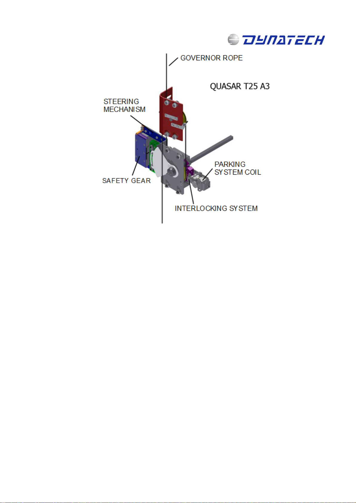
Figure 2: Components of the system
The rope runs along the governor and the diverter pulley’s grooves. The rope is in an open circuit, both ends being
tensed by spring-tensioning devices. This way, when the car reaches the tripping speed, the movement concerning
the governor rope will cause it to lock and operate the safety gears.
Figure 3 displays the QUASAR T25 A3 governor’s parking system. It is mainly made up of a coil, which operates the
governor’s interlocking system in case of UCM, and a micro-switch, which indicates the interlocking system’s
positioning to the D-Box.
Note: This manual displays partial information on the instructions for use and maintenance of this product. Please refer to the customer
area in Dynatech’s website in order to consult the full manual; http://customers.dynatech-elevation.com/
Instruction Manual: D-Box + QUASAR T25 A3 + ASG UD
Date: 18-12-17 Revision: 02 Cod: DYN62-3.02
5
Figure 3: QUASAR T25 A3 Governor
The protection of this system against UCM is as follows: The D-Box electronic system compares, at all times, the
status of the car doors and the floor level via input signals from the installation. These signals are:
D
oors closed.
Floor level,
Motor contactor
N.B.: Please check the electrical characteristics in the D-Box manual in order to verify the voltage of the signals to
be entered.
By using these inputs, if the D-Box detects that the car leaves door level with doors open, the contactor in the safety
line is activated, which causes the QUASAR T25 A3 governor’s parking system coil to de-energise. This will make
the parking system interlocking system operate on the governor’s centrifugal systems, thus causing the governor to
interlock.
Since the movement of the interlocking system is linked to the operating driving bar, when the governor interlocks,
the driving bar will operate on the safety gears thus causing them to jam and the car to brake.
Note: This manual displays partial information on the instructions for use and maintenance of this product. Please refer to the customer
area in Dynatech’s website in order to consult the full manual; http://customers.dynatech-elevation.com/
Instruction Manual: D-Box + QUASAR T25 A3 + ASG UD
Date: 18-12-17 Revision: 02 Cod: DYN62-3.02
6
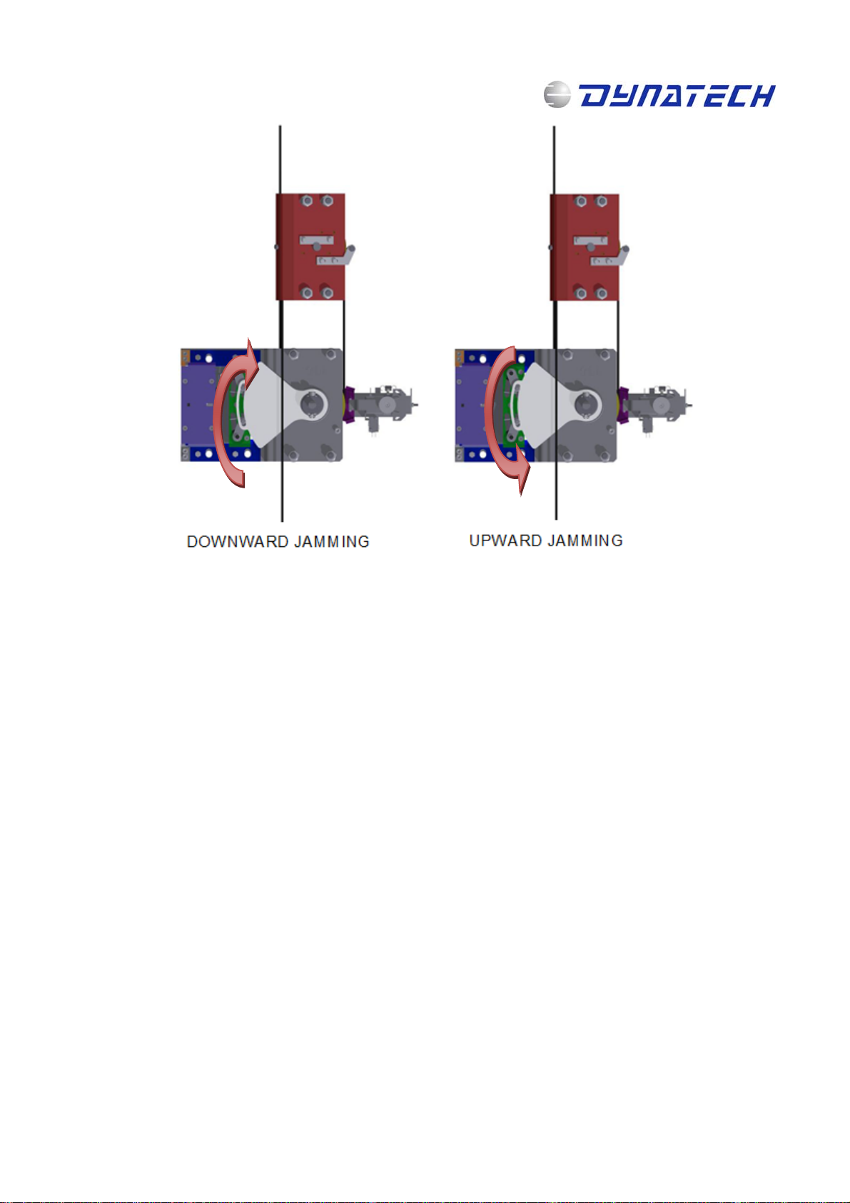
Figure 4: ASG UD Mechanism Operation
Under normal conditions, where no UCM is detected, the governor’s parking system 24V coil is energised, thus
preventing the parking system from interlocking the QUASAR T25 A3 governor. Therefore, the system operates in
positive safety.
4 ASSEMBLY AND MAINTENANCE
D-Box:
Only specialised and duly trained staff must carry out the assembly, electrical wiring and start-up. For further
information on assembly, the characteristics of the electrical wiring and wiring diagrams, please refer to the D-Box’s
manual for use and maintenance.
QUASAR T25 A3 + ASG UD:
The QUASAR T25 A3 Beta governor will be assembled and adjusted in accordance with the QUASAR T25 overspeed
governor's manual for use and maintenance.
Please check that the governor rope is correctly positioned and that the parking system is correctly operating, by
checking that the 24V coil is energised in normal operation.
Please check the distance from the safety gear brake shoe to the guide rail. Please also check that the governor
rope is correctly secured and operating onto the T-25 steering mechanism’s handle.
Please check periodically that no damage has occurred, which may put the normal use of the lift at a risk. The safety
gear’s friction components can be replaced. Visual inspection is enough.
Note: This manual displays partial information on the instructions for use and maintenance of this product. Please refer to the customer
area in Dynatech’s website in order to consult the full manual; http://customers.dynatech-elevation.com/
Other manuals for D-BOX
1
This manual suits for next models
2
Table of contents
Other Dynatech Industrial Equipment manuals


