Dyness B3 ESS B4870 User manual

B3 ESS Unit
User Manual

B3 ESS Unit User Manual
I
Content
Statement of Law .....................................................................................................................................1
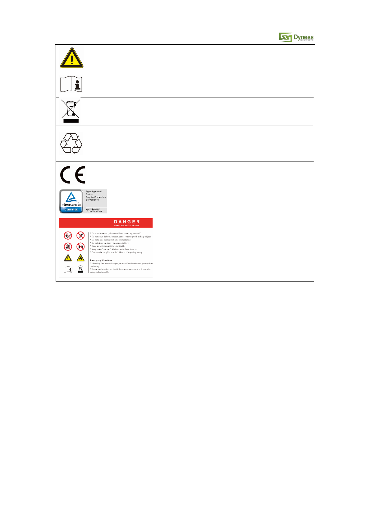
Safety Precautions.................................................................................................................................... 2
Preface...................................................................................................................................................... 3
1 Introduction.......................................................................................................................................... 4
1.1 Brief Introduction..........................................................................................................................4
1.2 Product Properties........................................................................................................................4
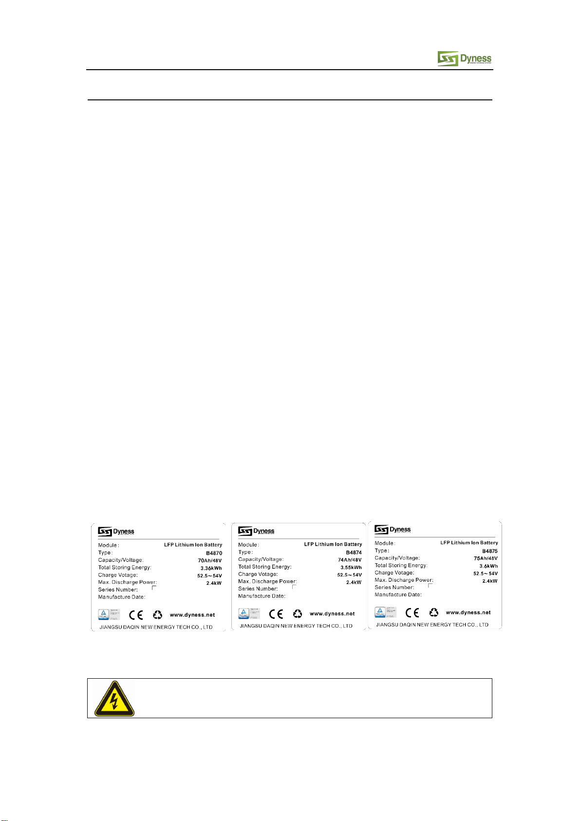
1.3 Product identity definition............................................................................................................4
2 Product Specification............................................................................................................................6
2.1 Size and Weight ............................................................................................................................6
2.2 Performance Parameter ...............................................................................................................6
2.3 Interface Definition....................................................................................................................... 6
2.3.1 DIP switch definition and description ....................................................................................7
2.4Battery Management System(BMS) ...........................................................................................10
2.4.1 Voltage Protection ..............................................................................................................10
2.4.2 Current Protection ..............................................................................................................10
2.4.3 Temperature Protection .....................................................................................................10
2.4.4 Other Protection ................................................................................................................. 11
3 Installation and Configuration ............................................................................................................12
3.1 Ready for installation..................................................................................................................12
3.1.1 Environmental requirements ..............................................................................................12
3.1.2 Tools and data.....................................................................................................................12
3.1.3 Technical preparation .........................................................................................................13
3.1.4 Unpacking inspection..........................................................................................................13
3.1.5 Engineering coordination....................................................................................................13
3.2 Equipment installation................................................................................................................14
3.2.1 Installation preparation .......................................................................................................15
3.2.2 Mechanical installation ........................................................................................................15
3.2.3 Electrical installation ...........................................................................................................16
4 Use, maintenance and troubleshooting .............................................................................................18
4.1 Battery system usage and operation instructions ......................................................................18
4.2Alarm description and processing...............................................................................................18
4.3Analysis and treatment of common faults..................................................................................19

B3 ESS Unit User Manual
1
Statement of Law
Copyright of this document belongs to Jiangsu Daqin New Energy Technology Co., Ltd.
No part of this documentation maybe excerpted, reproduced, translated,
annotated or duplicated in any form or by any means without the prior
written permission of Jiangsu Daqin New Energy Technology Co., Ltd. All Rights Reserved.
This product complies with the design requirements of environmental protection and personal
safety. The storage, use and disposal of the products shall be carried out in accordance with the
product manual, relevant contract or relevant laws and regulations.
Customer can check the related information on the website of Jiangsu Daqin New Energy
Technology Co., Ltd when the product or technology is updated. Web URL:
http://www.dyness.net/
Please note that the product can be modified without prior notice.
Revision History
Revision NO. Revision Date Revision Reason
1.0 2019.04.24 First Published
1.1 2019.06.24
1. System adds DIP switch
2. Renamed B4874 to B3
1.2 2019.07.29 Update the cable specification
修订历史产品版本

B3 ESS Unit User Manual
2
Safety Precautions
Warning
Please do not put the battery into water or fire, in case of explosion or any other situation
that might endanger your life.
Please connect wires properly while installation, do not reverse connect.
To avoid short circuit, please do not connect positive and negative poles with conductor
(Wires for instance).
Please do not stab, hit, trample or strike the battery in any other way.
Please shut off the power completely when removing the device or reconnecting wires during
the daily use or it could cause the danger of electric shock.
Please use dry powder extinguisher to put out the flame when encountering a fire hazard,
liquid extinguisher could result in the risk of secondary disaster.
For your safety, please do not arbitrarily dismantle any component in any circumstances
unless a specialist or an authorized one from our company, device breakdown due to
improper operation will not be covered under warranty.
Caution
We have strict inspection to ensure the quality when products are shipped out, however,
please contact us if case bulging or another abnormal phenomenon.
For your safety, device shall be ground connected properly before normal use.
To assure the proper use please make sure parameters among the relevant device are
compatible.
Please do not mixed-use batteries from different manufacturers, different types and models,
as well as old and new together.
Ambient and storage method could impact the life span and product reliability, please
consider the operation environment abundantly to make sure device works in proper
condition.
For long-term storage, the battery should be recharged once every 6 months, and the amount
of electric charge shall exceed 80% of the rated capacity.
Please charge the battery in 18 hours after it discharges fully and starts over-discharging
protection.
Formula of theoretical standby time: T=C/I (T is standby time, C is battery capacity, I is total
current of all loads).

B3 ESS Unit User Manual
3
Preface
Manual declaration
The B3 lithium iron phosphate battery energy storage system can provide energy storage
solutions for photovoltaic power generation users through parallel combination. During the day,
the excess power of photovoltaic power generation can be stored in the battery. At night or
when needed, the stored electrical energy can be used to supply power to the electrical
equipment, which can improve the efficiency of photovoltaic power generation, peak load
shifting, and emergency power backup.
This user manual details the basic structure, parameters, basic procedures and methods of
installation and operation and maintenance of the equipment.

B3 ESS Unit User Manual
4
1 Introduction
1.1 Brief Introduction
B3 lithium iron phosphate battery system is a standard battery system unit, customers can
choose a certain number of B3 according to their needs, by connecting parallel to form a
larger capacity battery pack, to meet the user's long-term power supply needs. The product
is especially suitable for applications with high operating temperatures, limited installation
space, long power backup time and long service life.
1.2 Product Properties
B3 energy storage product’s anode materials are lithium iron phosphate, battery cells are
managed effectively by BMS with better performance, the system’s features as below:
Comply with European ROHS, Certified SGS, employ non-toxic, non-pollution
environment-friendly battery.
Anode materials are lithium iron phosphate (LiFePO4), safer with longer life span.
Carries battery management system with better performance, possesses protection
function like over-discharge, over-charge, over-current, abnormal temperature.
Self-management on charging and discharging, Single core balancing function.
Intelligent design configures integrated inspection module, with 3 remote functions
(remote-measuring, remote-communicating and remote-controlling).
Flexible configurations allow parallel of multi battery for longer standby time.
Self-ventilation with lower system noise.
Less battery self-discharge, then recharging period can be up to 10 months during the
storage.
No memory effect so that battery can be charged and discharged shallowly.
With wide range of temperature for working environment, -20oC ~ +55 oC, circulation
span and discharging performance are well under high temperature.
Less volume, lighter weight.
1.3 Product identity definition
Figure1-1 Battery Energy Storage System nameplate
Battery voltage is higher than safe voltage, direct contact
with electric shock hazard.

B3 ESS Unit User Manual
5
Be careful with your actions and be aware of the dangers.
Read the user manual before using.
The scrapped battery cannot be put into the garbage can
and must be professionally recycled.
After the battery life is terminated, the battery can
continue to be used after it recycled by the professional
recycling organization and do not discard it at will.
This
battery product meets European directive
requirements.
This battery product passed the TUV certification test.
Dangerous goods warning label on the top of the battery
module

B3 ESS Unit User Manual
6
2 Product Specification
2.1 Size and Weight
Table 2-1 B3 Device size
Product Nominal
Voltage
Nominal
Capacity Dimension Weight
B3 DC48V70Ah 480×380×130mm ≈30kg
B3 DC48V 74Ah 480×380×130mm ≈31kg
B3 DC48V 75Ah 480×380×130mm ≈31kg
2.2 Performance Parameter
Table 2-2 B3 performance parameter
Item B3 Parameter value B3 Parameter value B3 Parameter value
Nominal Voltage(V) 48 48 48
Work Voltage Range(V) 42~54.75 42~54.75 42~54.75
Nominal Capacity(Ah) 70 74 75
Nominal Energy(kWh) 3.36 3.55 3.6
Nominal Power(kW) 1.0 1.06 1.08
Max Power(kW) 2.4 2.4 2.4
3S Peak Power(kW) 2.64 2.64 2.64
3S Peak Current(A) 55 55 55
Charging Current(A) 35 37 37.5
Discharge Current(A) 35 37 37.5
2.3 Interface Definition
This section elaborates on interface functions of the front interface of the device.
Figure2-1 The sketch of interface.
Table 2-3 Interface Definition
1
4
3
2
5
6
7
8
10
9
11

B3 ESS Unit User Manual
7
Item Name Definition
1 Power switch
OFF/ON,
must be in the "ON" state when in use
2
Ground
connection point
Shell ground connection
3 Positive socket Battery output positive or parallel positive line
4Negative socket Battery output negative or parallel negative line
5
SW (battery
wake/sleep
switch)
When the "OFF/ON" switch button is in the ON state, press
and hold this button for 3 seconds to put the battery into the
power-on or sleep state.
6 SOC
The number of green lights on shows the remaining battery
power. See Table 2-3 for details.
7 ALM
Red light flashing when an alarm occurs, red light always on
during protection status. After the condition of trigger
protection is released, it can be automatically closed.
8 RUN
Green light flashing during standby and charging mode.
Green light always on when discharging.
9 CAN/485
Communication cascade port, support CAN/ RS485
communication (factory default CAN communication)
10 DRY CONTACT /
11 ADD DIP switch
2.3.1 DIP switch definition and description
Table 2-4 Interface Definition
DIP switch position (host communication protocol and baud rate selection)
#1 #2 #3 #4
Baud rate selection
ON OFF
CAN: 250K,485: 115200 CAN: 500K,485: 9600
DIP switch description:
When the battery pack is connected in parallel, the host can communicate with the slave
through the CAN interface. The host summarizes the information of the entire battery system
and communicates with the inverter through CAN or 485. The connection mode is divided into
the following two cases:

B3 ESS Unit User Manual
8
1. If the host is the latest B4850 battery with DIP
switch:
(1) The communication line that communicates
with the inverter should use the one that the 6
and 7 pins are not short-circuited.
(2) After the battery module parallel line,
cascading line and communication line with
GOODWE, Solis, LUX, Sofar, DEYE, VICTRON,
IMEON, Voltronic, Sungrow, RENAC and DELIOS
inverters are connected, all B4850 batteries
should not be turned on first, be sure to put the
host DIP switch "# 3" to the "ON" position (to
the top), then turn on all the B4850 batteries.
(3) If the battery module is in communication
with the inverters of Growatt, GMDE, Saj or
AXPERT turn the host DIP switch "#2" to "ON"
position.
(4) If the battery module is in communication
with the GROWATT-SPF-off-grid inverter by 485
communication, turn the host DIP switch "#2"
and "#3" to "ON".
(5) The DIP switch of the slave does not need to
be changed.
(6) If the energy storage system has only one
B4850, it is the host itself, and still follow the
above steps.
Note: For more information of matching inverter
brands, please subject to the latest document
<The list of compatibility between Dyness ESS
and Inverters >.
2. If the host is a B4850 battery module
without the DIP switch:
(1) The communication line that
communicates with the inverter should
use the one that the 6 or 7 pins are short
circuit connection.
(2) After the battery module parallel line,
cascade line and the inverter
communication line are connected, turn
on all B4850 batteries.
(3) If there is a battery module with the
latest DIP switch in the slave, please do
not turn the DIP switch "#2" or "#3" to
"ON" position to avoid the slave and the
existing host grab the host communication
status, an error occurs.
Figure 2-2 CAN/485 interface definition

B3 ESS Unit User Manual
9
Table 2-4 Pin Definition
Foot position
Color
Definition
PIN1
Orange/white
485A
PIN2
Orange
XGND
PIN3
Green/white
485B
PIN4
Blue
CANH
PIN5
Blue/white
CANL
PIN6
Green
Reserve
PIN7
Brown/white
XIN
PIN8
Brown
Reserve
PIN9
Orange/white
Reserve
PIN10
Orange
XGND
PIN11
Green/white
Reserve
PIN12
Blue
CANH
PIN13
Blue/white
CANL
PIN14
Green
Reserve
PIN15
Brown/white
XOUT
PIN16
Brown
Reserve
Table 2-5 LED status indicators
Battery
Status
SOC LED1 LED2 LED3 LED4 ALM RUN
Shutdown / off off off off off off
Standby
75%
≤
SOC
≤
100%
●●●●off Blinking
50%≤SOC<75% ●●●off off Blinking
25%≤SOC<50% ●●off off off Blinking
5%<SOC<25% ●off off off off Blinking
0%<SOC≤5% ●off off off Blinking Blinking
SOC=0 off off off off Blinking Blinking
Charging
SOC=100% ●●●●●Blinking
75%≤SOC<100% ●●●Blinking off Blinking
50%≤SOC<75% ●●Blinking off off Blinking
25%≤SOC<50% ●Blinking off off off Blinking
0%<SOC<25% Blinking off off off off Blinking
Front
Plug
Socket of communication port
CAN/485

B3 ESS Unit User Manual
10
Battery
Status
SOC LED1 LED2 LED3 LED4 ALM RUN
Discharging
75%
≤
SOC
≤
100%
●●●●off ●
50%≤SOC<75% ●●●off off ●
25%≤SOC<50% ●●off off off ●
5%<SOC<25% ●off off off off ●
0%<SOC≤5% ●off off off Blinking ●
SOC=0 off off off off ●Blinking
●means green light always on ●means red light always on
Blinking: means green light flashing Blinking: means red light flashing
2.4 Battery Management System(BMS)
2.4.1 Voltage Protection
Discharging Low Voltage Protection:
When any battery cell voltage is lower than the protection value during discharging, the over-
discharging protection starts, and the battery buzzer makes an alarm sound. Then battery system
stops supplying power to the outside. When the voltage of each cell recovers to rated return range,
the protection is over.
Charging Over Voltage Protection:
When total voltage or any battery cell voltage reaches the protection value during charging,
battery stops charging. When total voltage or a cell recover to rated return range, the protection
is over.
2.4.2 Current Protection
Over Current Protection in Charging:
When the charging current is greater than the protection value, the battery buzzer alarms and the
system stops charging. Protection is removed after rated time delaying.
Over Current Protection in Discharging:
When the discharge current is greater than the protection value, the battery buzzer alarms and
the system stops discharging. Protection is released after rated time delaying.
Note:
The buzzer sound alarm setting can be manually turned off on the background software, and the
factory default is on.
2.4.3 Temperature Protection
Less/Over temperature protection in charging:
When battery’s temperature is beyond range of 0 ℃~+55 ℃during charging, temperature
protection starts, device stops charging.
The protection is over when it recovers to rated return range.
Less/Over temperature protection in discharging:
When battery’s temperature is beyond range of -20℃~+55℃during discharging, temperature
protection starts, device stops supplying power to the outside.

B3 ESS Unit User Manual
11
The protection is over when it recovers to rated return range.
2.4.4 Other Protection
Short Circuit Protection:
When the battery is activated from the shutdown state, if a short circuit occurs, the system starts
short-circuit protection for 30 seconds.
Self-Shutdown:
When device connects no external loads and power supply and no external communication for over
72 hours, device will dormant standby automatically.
Caution
Battery’s maximum discharging current should be more than load’s maximum working current.

B3 ESS Unit User Manual
12
3 Installation and Configuration
3.1 Ready for installation
Safety Requirement
This system can only be installed by personnel who have been trained in the power supply system
and have sufficient knowledge of the power system.
The safety regulations and local safety regulations listed below should always be followed during
the installation.
All circuits connected to this power system with an external voltage of less than 48V
must meet the SELV requirements defined in the IEC60950 standard.
If operating within the power system cabinet, make sure the power system is not
charged. Battery devices should also be switched off.
Distribution cable wiring should be reasonable and has the protective measures to
avoid touching these cables while operating power equipment.
when installing the battery system, must wear the protective items below:
The isolation gloves Safety goggles Safety shoes
Figure3-1
3.1.1 Environmental requirements
Working temperature: -20 oC ~ +55 oC
•Charging temperature range is 0oC~+55 oC,
•Discharging temperature range is -20 oC ~+55 oC
Storage temperature: -10 oC ~ +35 oC
Relative humidity: 5% ~ 85%RH
Elevation: no more than 4000m
Operating environment: Indoor installation, sites avoid the sun and no wind, no
conductive dust and corrosive gas.
And the following conditions are met:
•Installation location should be away from the sea to avoid brine and high humidity
environment.
•The ground is flat and level.
•There is no flammable explosive near to the installation places.
•The optimal ambient temperature is 15oC ~ 30 oC
•Keep away from dust and messy zones
3.1.2 Tools and data
Hardware tool
Tools and meters that may be used are shown in table 3-1.
Table 3-1 Tool instrument
Name
Screwdriver (word, cross) AVO meter
Wrench Clamp meter
Inclined pliers Insulating tape
Needle nose pliers The thermometer

B3 ESS Unit User Manual
13
Name
Clip forceps Wrist strap
Wire stripper AVO meter
Electric drill Tape
3.1.3 Technical preparation
Electrical interface check
Devices that can be connected directly to the battery can be user equipment, power
supplies, or other power supplies.
Confirm whether the user's PV power generation equipment, power supply or other
power supply equipment has a DC output interface, and measure whether the DC
power output voltage meets the voltage range requirements in Table 2-2.
Confirm that the maximum discharge current capability of the DC power interface of
the user's photovoltaic power generation equipment, power supply or other power
supply equipment should be greater than the maximum charging current of the
products used in Table 2-2.
If the maximum discharge capacity of the DC power interface of the user's
photovoltaic power generation equipment is less than the maximum charging
current of the products used in Table 2-2, the DC power interface of the user's
photovoltaic power generation equipment shall have a current limiting function to
ensure the normal operation of the user’s equipment.
Verify that the maximum operating current of the battery-powered user equipment
(inverter DC input) should be less than the maximum discharge current of the
products used in Table 2-2.
The security check
Firefighting equipment should be provided near the equipment, such as portable dry
powder fire extinguisher.
Automatic fire fighting system shall be provided for the case where necessary.
No flammable, explosive and other dangerous articles are placed beside the battery.
3.1.4 Unpacking inspection
When the equipment arrives at the installation site, loading and unloading should
be carried out according to the rules and regulations, to prevent from being exposed
to sun and rain.
Before unpacking, the total number of packages shall be indicated according to the
shipping list attached to each package, and the case shall be checked for good
condition.
In the process of unpacking, handle with care and protect the surface coating of the
object.
Open the package, the installation personnel should read the technical documents,
verify the list, according to the configuration table and packing list, ensure objects
are complete and intact, if the internal packing is damaged, should be examined and
recorded in detail.
Packing list is as follows:
Item Specification Quantity Figure
Battery-B3
48V/70Ah or
48V/74Ah or
48V/75Ah
480×380×130mm
1

B3 ESS Unit User Manual
14
3.1.5 Engineering coordination
Attention should be paid to the following items before construction:
Power line specification.
The power line specification shall meet the requirements of maximum discharge
current for each product.
Mounting space and bearing capacity.
Make sure that the battery has enough room to install, and that the battery rack and
bracket have enough load capacity.
Wiring.
Make sure the power line and ground wire are reasonable. Not easy to short-circuit,
water and corrosion.
3.2 Equipment installation
Table 3-2 Installation steps
Step1 Installation
preparation
Confirm that the ON/OFF switch on the front panel of B3
unit is in the “OFF” state to ensure no live operation.
Step 2 Mechanical
installation
1. Cabinet placement position determination
2. Top cable harness pre-installed
3. Battery module installation
Power cable-
positive
Red
/25mm2/L2050mm 1
Power cable-
negative
Black
/25mm2/L2050mm 1
Parallel cable-
positive
Red
/25mm2/L215mm 1
Parallel cable-
negative
Black
/25mm2/L215mm 1
Communication
parallel cable
Black
/L250mm/Double
RJ45 plug
1
Communication
cable-to inverter
Black
/L2000mm /Double
RJ45 plug
1

B3 ESS Unit User Manual
15
Step3 Electrical
installation
1. Ground cable installation
2. Battery module parallel cable installation
3. Battery module total positive cable installation
4. Battery module total negative cable installation
5. Internal CAN communication interface connection
Step4Battery system
self-test
1. Press the ON/OFF switch to the "ON" state
2. BMS system power-on activation
3. Check the system output voltage
4. Shut down the system
Step5Connecting
inverter
1. Connect total positive & total negative cable of the
battery system to the inverter
2. Connect the external CAN communication cable to
the inverter
3.2.1 Installation preparation
1. Prepare equipment and tools for installation.
2. Check the B3 unit and confirm that the ON/OFF switch is in the "OFF" state to ensure no
live operation.
3.2.2 Mechanical installation
Installation method:
Figure3-2
Figure3-3
Installation method 2: With Simple bracket installation
1. Place the B3 unit on the cabinet
bracket as shown in the figure and
push it into the cabinet to the
installation position. (The cabinet
structure in the figure is for
reference only)
2. Secure the B3 unit to the cabinet
with a nut through the mounting
holes top on the hanging ears of the
B3 unit.

B3 ESS Unit User Manual
16
Figure3-4
Figure3-5
Figure3-6
3.2.3 Electrical installation
Before connecting the power cables, using multimeter to measure cable continuity,
short circuit, confirm positive and negative, and accurately mark the cable labels.
Measuring methods:
•Cable availability: select the buzzer and use the probe to measure the ends of the
same color cable. If the buzzer calls, it means the cable is available.
•Short circuit judgment: choose multimeter resistor file, probe the same end of
positive and negative pole, if the resistor shows infinity, means that the cable is
available.
•After visual testing of power line is connected well, the positive and negative
poles of the battery shall be connected respectively to the positive and negative
poles of the opposite terminal.
It is better to add a circuit breaker between the inverter and the battery system. The selection of
the circuit breaker requires:
Voltage: U>60V
Current: I = Inverter power
45V
1. As shown in the
figure3-4, place two B3
brackets side by side
with a spacing of
300mm and push the
B3 in.
2. Ensure that the B3 hanging
ears are aligned with the
bracket and secure the
hanging ears to the bracket
with four M6 screws.
3. Stack the fixed B3 and the
bracket as shown in the
figure 3-6, and fasten the
buckle between the
upper and lower sides.

B3 ESS Unit User Manual
17
The circuit breaker is installed between the battery module and the inverter, as shown in Figure
3-7:
No.1 No.2 No.3 No.4
Figure3-7
Note: If the inverter is one of GOODWE, Solis, LUX, Sofar, DEYE, VICTRON, IMEON, Voltronic,
Sungrow, RENAC and DELIOS the DIP switch mode of the host is shown in No.1.
If the inverter is one of Growatt, GMDE Saj, and AXPERT the DIP switch mode of the host is
shown in No.2.
If the battery module is in communication with the GROWATT-SPF-off-grid inverter by 485
communication, the DIP switch mode of the host is shown in No.3.
The DIP switch mode of the slave does not need to move, as shown in No.4.
Note: For more information of matching inverter brands, please subject to the latest document
<The list of compatibility between Dyness ESS and Inverters >.
Power cable-
negative
Power cable-
positive
Parallel cable-
positive
Parallel cable-
negative
Communication
cable-to inverter
Communication
parallel cable
Circuit
breaker
Inverter

B3 ESS Unit User Manual
18
4 Use, maintenance and troubleshooting
4.1 Battery system usage and operation instructions
After completing the electrical installation, follow these steps to start the battery system.
1Refer to the description of the DIP switch of 2.3.1 to prepare the battery module
before starting up, then press the ON/OFF button to the ON position, press and hold
the SW button for 3 seconds.
After the indicator self-test, the RUN indicator will light and the SOC indicator will be
on (100% SOC status in the Figure4-1).
Figure4-1
Note:
After pressing the power button, if the battery status indicator on the front panel
continues to be red, please refer to the "4.2 Alarm description and processing ". If
the failure cannot be eliminated, please contact the dealer timely.
2Use a voltmeter to measure whether the voltage of the circuit breaker battery
access terminal is greater than 37V, and check whether the voltage polarity is
consistent with the inverter input polarity. If the circuit breaker battery input
terminal has a voltage output and is greater than 37V, then the battery has started
normal work.
3After confirming that the battery output voltage and polarity are correct, turn on
the inverter, close the circuit breaker.
4Check if the indicator of the inverter and battery connection (communication
indicator and battery access status indicator) is normal. If it is normal, successfully
complete the connection between the battery and the inverter. If the indicator
light is abnormal, please refer to the inverter manual for the cause or contact the
dealer.
4.2 Alarm description and processing
When the protection action or fault occurs in the system, the alarm signal will be given
through the working status indicator on the front panel of the B3. The network
management can query the specific alarm categories.
If the fault such as single cell overvoltage, charging over-current, under-voltage
SW
SOC
ALM
CAN/485
IN
OUT
DRY CONTACT
RUN
This manual suits for next models
3
Table of contents
Other Dyness Camera Accessories manuals