Dyness PowerDepot H5 User manual

V1.1
PowerDepot H5
User Manual

PowerDepot H5 series User Manual
I
Content
Statement of Law.................................................................................................. II
Safety Precautions ............................................................................................... III
Preface ................................................................................................................ IV
1 Introduction .................................................................................................... 1
1.1 Brief Introduction.................................................................................................1
1.2 Product Properties ...............................................................................................1
1.3 Product identity definition ...................................................................................2
2 Product Specification....................................................................................... 3
2.1 Size and Weight....................................................................................................3
2.2 Performance Parameter .......................................................................................3
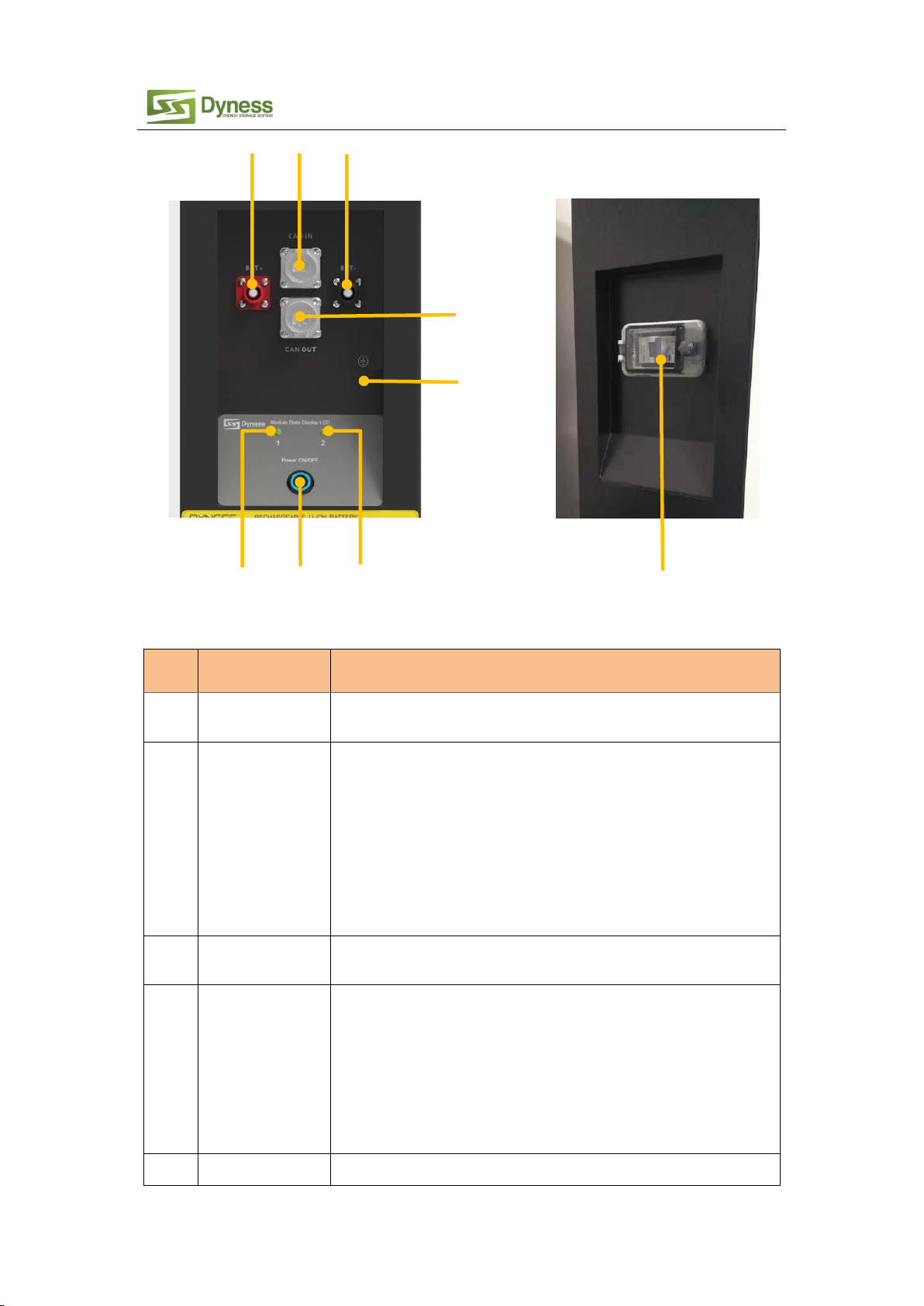
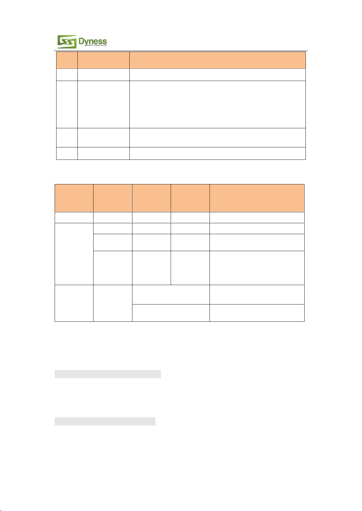
2.3 Interface Definition .............................................................................................. 3
2.4 Battery Management System(BMS) ......................................................................5
2.4.1 Voltage Protection................................................................................................................5
2.4.2 Current Protection................................................................................................................6
2.4.3 Temperature Protection .......................................................................................................6
2.4.4 Other Protection ..................................................................................................................6
3 Installation and Configuration ......................................................................... 7
3.1 Preparations for installation ................................................................................. 7
3.1.1 Environmental requirements ...............................................................................................7
3.1.2 Tools and data ......................................................................................................................8
3.1.3 Technical preparation...........................................................................................................8
3.1.4 Unpacking inspection...........................................................................................................8
3.1.5 Engineering coordination...................................................................................................10
3.2 Equipment installation ....................................................................................... 10
3.2.1 Floor installation.................................................................................................................11
3.2.2 Mounted on the wall..........................................................................................................12
3.2.3 Electrical installation ..........................................................................................................14
3.2.4 Battery module DIP switch definition and description.......................................................18
3.2.5 Battery parameter settings on the inverter .......................................................................24
3.2.6 Register on the website after installation..........................................................................24
4 Use, maintenance and troubleshooting...........................................................25
4.1 Battery system usage and operation instructions ................................................ 25
4.2 Alarm description and processing ....................................................................... 26
4.2.1 Alarm and countermeasure for affecting system output .................................................26
4.2.2 Alarm and countermeasure for un-affecting system output..............................................26

PowerDepot H5 series User Manual
II
4.3 Analysis and treatment of common faults........................................................... 27
Statement of Law
Copyright of this document belongs to Daqin New Energy Tech (Taizhou) Co., Ltd.
No part of this documentation maybe excerpted, reproduced, translated, annotated or duplicated
in any form or by any means without the prior written authorization of Daqin New Energy Tech
(Taizhou) Co., Ltd. All Rights Reserved.
This product complies with the design requirements of environmental protection and personal
safety. The storage, use and disposal of the products shall be carried out in accordance with the
product manual, relevant contract or relevant laws and regulations.
Customer can check the related information on the website of Daqin New Energy Tech (Taizhou)
Co., Ltd when the product or technology is updated. Web URL:http://www.dyness-tech.com.cn
Please note that the product can be modified without prior notification.
Manual Version: V1.1
Revision History
Revision NO.
Revision
Date
Revision Reason
1.0
2020.4.30
First Published
1.1
2020.09.28
1. Add new inverters in DIP switch description

PowerDepot H5 series User Manual
III
Safety Precautions
Warning
⚫Please do not put the battery into water or fire, in case of explosion or any other situation that
might endanger your life.
⚫Please connect wires properly while installation, do not reverse connect.
⚫To avoid short circuit, please do not connect positive and negative poles with conductor on the
same device.
⚫Please avoid any form of damage to battery, especially stab, hit, trample or strike.
⚫Please shut off the power completely when removing the device or reconnecting wires during
the daily use or it could cause the danger of electric shock.
⚫Please use dry powder extinguisher to put out the flame when encountering a fire hazard,
liquid extinguisher could result in the risk of explosion.
⚫For your safety, please do not arbitrarily dismantle any component in any circumstances. The
maintenance must be implemented by authorized technical personnel or our company’s
technical support. Device breakdown due to unauthorized operation will not be covered under
warranty.
Caution
⚫The products have been strictly checked before shipment. Please contact us if you find any
abnormal phenomena such as device outer case bulging.
⚫In order to ensure safety and normal use of the product, the equipment should be grounded
properly before use.
⚫To assure the product normal operation, please make sure parameters among the relevant
device are compatible and matched.
⚫Please do not mixed-use batteries from different manufacturers, different types and
models, as well as old and new together.
⚫Ambient and storage method could impact the product life span, please comply with the
operation environment instruction to ensure device works in proper condition.
⚫For long-term storage, the battery should be recharged once every 6 months, and the
amount of electric charge shall exceed 80% of the rated capacity.
⚫Please charge the battery in 18 hours after it’s fully discharged or over-discharging
protection mode is activated.
Formula of theoretical standby time: T=C/I (T is standby time, C is battery capacity, I is total
current of all loads).
⚫The surface of the PowerDepot H5 cabinet is affixed with a torn invalid label. Therefore,
before opening the cover to change the DIP switch mode, you need to contact and inform us
the product ID. We will record this battery ID and authorize the opening operation to be
performed. Except for changing the DIP switch mode, no other operations are allowed. In
the next stage, you can log in on our website to apply for operating authorization directly.

PowerDepot H5 series User Manual
IV
Preface
Manual Description
PowerDepot H5 Lithium Iron Phosphate Battery is external battery module which can store the
electricity for home use. When you apply the grid or photovoltaic system as your powers supply,
the product can collect electricity to charges the battery. When grid or photovoltaic system is
power off , the product can supply electricity itself for your home loads.
PowerDepot H5 User manual included the device structure, parameters, basic procedure and
method of installation, operation, maintenance.
Safety Statement
⚫Only qualified and trained professionals are qualified to install, operate, maintain the device.
⚫Please comply with local safety regulations and operational rules during installation,
operation and maintenance, or it could cause unexpected injury or device damage.
⚫The safety declaration mentioned in the manual are only supplement context for your local
safety regulations.
⚫The seller does not undertake any responsibility for device operations or usage of violating
general safety requirements and safety standards.
Sign explanation
User should clear the meaning of the caution sign below when configuring or operating
PowerDepot H5 series products.
Caution
Neglecting the warnings might cause equipment failure.

PowerDepot H5 series User Manual
1
1 Introduction
1.1 Brief Introduction
PowerDepot H5 series is equipped with lithium iron phosphate battery for family use . We
base on customer needs and market requirement to develop cutting-edge battery storage
technology and offer this high quality product to supply stable electricity for all kind of user’
s devices. The products have long life span and can be applied in high temperature
environment and take less space for installation.
PowerDepot H5 series carries self-developed battery management system. When you apply
the grid or photovoltaic system as your powers supply, the products can collect electricity
to charges the battery. When grid or photovoltaic system is power off , the products can
supply electricity itself for your home loads. Products also can be paralleled to build a multi-
module system with more capacity to satisfy the longtime energy storage demand.
1.2 Product Properties
PowerDepot H5 series energy storage product’s anode materials are lithium iron phosphate,
battery cells are managed effectively by BMS with better performance.
The systems features as below:
⚫Comply with European ROHS, Certified SGS, employ non-toxic, non-pollution
environment-friendly battery.
⚫Anode materials are lithium iron phosphate (LiFePO4), high safety performance, longer
life span.
⚫Equipped with BMS (battery management system) mode, with protection function like
over-discharge, over-charge, over-current, abnormal temperature.
⚫Self-management on charging and discharging, Single core balancing function.
⚫Intelligent design configures integrated inspection module.
⚫Flexible configurations, allow parallel of multi-battery for longer standby time.
⚫Self-ventilation, lower system noise.
⚫Less battery self-discharge, then recharging period can be up to 10 months during the
storage.
⚫No memory effect so that battery can be charged and discharged shallowly.
⚫With wide range of temperature for working environment, -20oC ~ +55 oC, products’ life
span and discharging performance are well under high temperature.
⚫Less volume, lighter weight, seal grade up to IP65 embedding design for easier
installation and maintenance.

PowerDepot H5 series User Manual
2
1.3 Product identity definition
FIG1-1 Battery Energy Storage System nameplate
Battery voltage is higher than safe voltage, direct contact may cause
electric shock hazard.
Be careful with your actions and be aware of the dangers.
Read the user manual before using.
The scrapped battery cannot be put into the garbage can and must be
professionally recycled.
After the battery life is terminated, the battery can continue to be
used after it recycled by the professional recycling organization and
do not discard it at will.
This battery product meets European directive requirements.

PowerDepot H5 series User Manual
3
2 Product Specification
2.1 Size and Weight
Table 2-1 PowerDepot H5 series device model
Specification
Model
Nominal
Voltage
Nominal
Capacity
Dimension
(mm)
Weight
(kg)
IP Level
PowerDepot H5
-5.0
48V
100Ah
574*228*600mm
65kg
IP65
PowerDepot H5
-2.5
48V
50Ah
574*228*600mm
44kg
IP65
2.2 Performance Parameter
Table 2-2 PowerDepot H5 performance parameter
Item
PowerDepot H5 -2.5
PowerDepot H5 -5
Nominal Voltage(V)
48V
48V
Work Voltage Range(V)
42~54
42~54
Nominal Capacity(Ah)
50Ah
100Ah
Nominal Energy(kWh)
2.4
4.8
Nominal Power(kW)
0.7
1.5
Max Power(kW)
2.4
4.8
1S Peak Power(kW)
2.64
5.28
1S Peak Current(A)
55
110
Charging Current(A)
25
50
Discharge Current(A)
25
50
2.3 Interface Definition
This section elaborates on interface functions of the front panel of the device.
Figure2-1 PowerDepot H5 the sketch of front interface.

PowerDepot H5 series User Manual
4
Table 2-3 Interface Definition
Item
Name
Definition
1
Positive socket
The battery DC output positive pole, which is connected to the
positive pole of the inverter through the cable
2
COM IN
When the system is used independently:
The CAN/RS485 socket is connected to the inverter CAN/RS485
interface through the communication cable.
When the system is used in parallel:
This CAN/RS485 communication socket is connected to the COM
OUT interface of the previous PowerDepot H5 through
communication cable.
(Factory default CAN communication mode)
3
Negative socket
The battery DC output negative pole, which is connected to the
negative pole of the inverter through the cable
4
COM OUT
When the system is used independently:
This CAN/RS485 socket is a reservation interface
When the system is used in parallel:
This CAN/RS485 communication socket is connected to the COM IN
interface of the next PowerDepot H5 through communication
cable.
(Factory default CAN communication mode)
5
LED1
Module 1 status indicator light
5
9
4
7
6
8
1
2
3

PowerDepot H5 series User Manual
5
Item
Name
Definition
6
LED2
Module 2 status indicator light
7
Reset switch
Press the switch and the battery system turn on.
When the battery is in the non-use state such as storage,
transportation etc., it needs to be turn off by pressing the Reset
switch button, and the battery system will automatically sleep after
the device without external load and power for 72 hours.
8
Ground
connection point
Shell ground connection
9
DC circuit breaker
Circuit protection
Table 2-4 LED status indicators (Take PowerDepot H5-5.0 as an example)
State
Protect/Alar
m/Normal
Led1
Led2
Directions
Shut down
off
off
All off
Stand-
by/Charging/
Discharging
Normal
●
●
Always on,11%≤SOC≤100%
Alarm
●
●
Always on, Corresponding module
alarm or 0%<SOC≤10%
Protection
●
●
Flashing, (Corresponding module
protection be activated / Over-
discharge protection /Over-current
protection / Temperature abnormality,
etc.)
Other case
Alarm
Yellow, green and red flash
alternately
All module address assignments in the
system are incomplete
The master PowerDepot H5
LED1 yellow flash
Communication failure between
batteries
2.4 Battery Management System(BMS)
2.4.1 Voltage Protection
Low Voltage Protection in Discharging:
When any module cell voltage is lower than the rated protection value during discharging, the over-
discharging protection be activated, and the battery buzzer makes alarm sound. Then battery
system stops supplying power to the outside. When the voltage of each cell recovers to rated value
and total voltage restored to above 45V, the protection is released.
Over Voltage Protection in Charging:
During charging stage, the system will stop charging when the total voltage of the battery pack is
higher than rated value or the voltage of any single cell reaches the protection value. When the
total voltage returns to below 52V and the cell voltage back to below the rated protection value,
the protection is released.

PowerDepot H5 series User Manual
6
2.4.2 Current Protection
Over Current Protection in Charging:
When the charge current of each module>45A, current limit protection mode is activated, current
will be limited to 5A,protection is removed after rated time delaying 10S. Circulate like this until
the current is lower than 45A.
Over Current Protection in Discharging:
When the discharge current is higher than the protection value 55A, the battery buzzer alarms and
the system stops discharging. The system is released from protection after the rated delay time of
1min.
Note:
The buzzer sound alarm setting can be turned off on the background software manually, and the
factory default is on.
2.4.3 Temperature Protection
Low/Over temperature protection in charging:
When battery’s temperature is beyond range of -5oC~+55oC during charging, temperature
protection be activated, device stops charging. The protection is released when it back to rated
range of working temperature.
Low/Over temperature protection in discharging:
When battery’s temperature is beyond range of -20oC ~+55oC during discharging, temperature
protection be activated, device stops supplying power to the outside. The protection is released
when it back to rated range of working temperature.
2.4.4 Other Protection
Short Circuit Protection:
When the battery is activated from the off state, if a short circuit occurs, the DC circuit breaker will
respond first. If the DC circuit breaker does not operate, the short circuit protection function of
BMS will be activated automatically and cut off the device’s output.
Self Shutdown:
When device have no connection of external loads, power supply and communication equipment
for over 72 hours, the device will go into hibernation automatically.
Caution
The maximum operating current required for the electrical load shall be less than the maximum
discharge current capacity of the battery.

PowerDepot H5 series User Manual
7
3 Installation and Configuration
3.1 Preparations for installation
Safety Requirement
The product can only be installed by personnel who have been trained in the power-supply system
and have sufficient knowledge of the electrical power system.
The safety regulations and local safety regulations listed below should always be followed during
the installation.
⚫All circuits connected to this power system with an external voltage of less than 48V
must meet the SELV requirements defined in the IEC60950 standard.
⚫If operating within the power system cabinet, make sure the power system is not
charged. Battery devices should also be switched off.
⚫Distribution cable wiring should be reasonable and has the protective measures to
avoid touching these cables while operating power equipment.
⚫when installing the battery system, must wear the protective items below:
The isolation gloves Safety goggles Safety shoes
3.1.1 Environmental requirements
Working temperature: -20 oC ~ +55 oC
•Charging temperature range is 0oC~+55 oC,
•Discharging temperature range is -20 oC ~+55 oC
Storage temperature: -10 oC ~ +35 oC
Relative humidity: 5% ~ 85%RH
Elevation: no more than 4000m
Operating environment: Indoor or outdoor installation should avoid the sunlight and wind,
no conductive dust and corrosive gas.
The following conditions shall be met:
•Installation location should be away from the sea to avoid corrosion from brine or
high humidity environment.
•The ground for product arrangement shall be flat and level.
•Ensure there is no flammable explosive materials near to the installation places.
•The optimal ambient temperature is 15oC ~ 30 oC
•Keep away from dust and messy zones

PowerDepot H5 series User Manual
8
3.1.2 Tools and data
Tools and meters that may be used for installation are shown in table 3-1.
Table 3-1 Tool instrument
Name
Screwdriver(Slotted、Phillips)
Multimeter
Torque wrench
Clamp current meter
Diagonal pliers
Insulation tape
Pointed nose pliers
Temperature meter
Pliers to hold the wire
Anti-static bracelet
Stripping pliers
Cable tie
Electric drill
Tape measure
3.1.3 Technical preparation
Electrical interface check
Devices that can be connected directly to the battery can be user’s equipment, power
supplies , or other power supply equipment.
⚫Confirm whether the user’s equipment, the PV equipment or other power supply
equipment has the DC output interface, and measure whether the output voltage of
the interface meets the requirements of the voltage range of table 2-2
⚫Verify the maximum discharge current capacity of the user’s equipment, the PV
equipment or other power supply equipment. The DC standby interface, and the
maximum discharge current shall be higher than the maximum charging current of
the products used in table 2-2.
⚫If DC interface maximum discharge capacity of the user’s equipment is less than the
maximum charging current of products using in table 2-2, the user’s interface should
have the power equipment of DC current limiting function to ensuring the normal
work of user equipment.
The security check
⚫Firefighting equipment should be arranged near the equipment, such as portable dry
powder fire extinguisher.
⚫Automatic fire fighting system shall be provided for the case where necessary.
⚫Flammable, explosive and other dangerous materials placed beside the battery are
prohibited.
3.1.4 Unpacking inspection
⚫When the equipment arrives at the installation site, loading and unloading should
be carried out according to the rules and regulations, so as to prevent from being
exposed to sunlight and rain.
⚫Before unpacking, the total number of packages shall be indicated according to the
shipping list attached to each package, and the case shall be checked for good
condition.

PowerDepot H5 series User Manual
9
⚫In the process of unpacking, handle with care and protect the surface coating of the
object.
⚫Open the package, the professional installation personnel should read the technical
documents, verify the list, according to the configuration table and packing list,
ensure objects are complete and intact. If the internal packaging is damaged, it must
be inspected and recorded in detail.
Packing list is as follows:
Battery×1
Battery bottom bracket ×1
Support bracket ×2
M6 bolt ×8
Fixing battery box with battery
bracket
Power cable ×2
connect battery with inverter
Standard
Communication cable ×1
User manual ×1
Positioning cardboard×2
Expansion screw ×8
120ΩCAN resistor ×1
RJ45 Waterproof connector ×2

PowerDepot H5 series User Manual
10
3.1.5 Engineering coordination
Attention should be paid to the following items before construction:
⚫Power cable specification.
⚫The power cable specification shall meet the requirements of maximum discharge
current for each product.
⚫Mounting space and bearing capacity.
⚫Make sure that the battery has enough space to install, and that the battery rack and
bracket have enough load capacity.
⚫Wiring.
⚫Make sure the power cable and ground wire are reasonable. Not easy to short-circuit,
water and corrosion.
3.2 Equipment installation
The wall for battery installation shall be solid brick or cement wall with strong bearing capacity and
wall thickness no less than 100mm.
Mounting space requirements:
Floor installation Wall installation

PowerDepot H5 series User Manual
11
Table 3-2 Installation steps
Step1
System outage
1. Ensure that the battery is in a shutdown state
(Disconnect the battery power cable and press the Reset
button to turn it off)
Step 2
Mechanical
installation
1. bracket check
2.Equipment installation
Step3
Electrical
installation
1. Connect the grounding cable
2 Electrical installation
3.Connect inverter
4.Communication interface connection
3.2.1 Floor installation
When the battery system is placed directly on the ground, a fixed support must be used to fix the
top of the battery box on the wall.
1.Use the positioning cardboard
(provided in accessory package)
and mark the screw hole positions
on the wall, as shown four holes
in the picture on the left.
2.The bottom of the board must be
in horizontal touch with the
ground while marking the holes.
3.According to the marked position, use
an electric drill to drill 4 holes with a
diameter of 10mm on the wall for
installing M6 expansion bolts. The
depth of the holes should be greater
than 70mm.

PowerDepot H5 series User Manual
12
3.2.2 Mounted on the wall
The following accessories need to be added when install the battery on the wall.
Battery bottom bracket ×1 Expansion screw ×4
4.Fixing the shell of the M6 expansion
bolt into the hole on the wall.
5.Use the M6 bolt to fix the Support
bracket on the wall and control the
torque force at 6NM.
6.Carry the battery box to the
installation site, and place it at
15mm away from the wall surface.
Connect the support bracket and
the battery box with M6 bolts.

PowerDepot H5 series User Manual
13
Installation procedure:
1.Use the positioning cardboard
(provided in accessory package) and
mark the screw hole positions on the
wall, as shown eight holes in the picture
on the left.
2.The cardboard must be perpendicular
to the ground while marking the holes.
3.The bottom of the cardboard is about
300mm to the ground.
4.According to the marked position, use
an electric drill to drill 8 holes with a
diameter of 10mm on the wall for
installing M6 expansion bolts. The depth
of the holes should be greater than
70mm.
5. Fixing the shell of the M6 expansion
bolt into the hole on the wall, and fix
the Support bracket and Battery bottom
bracket on the wall with M6 bolts and
control the torque force 6NM.

PowerDepot H5 series User Manual
14
3.2.3 Electrical installation
Use multimeter to measure the device before power cable connection procedure. Check
the cable continuity, confirm positive and negative and mark the cable labels.
Measuring methods:
⚫Power cable check: select the buzzer mode of multimeter and detect the both ends
of the same color cable. If the buzzer calls, it means the cable is in good condition.
⚫After visual testing of power line connection, the positive and negative poles of the
battery shall be connected respectively to the positive and negative poles of another
device (inverter).
Connect the battery box to the ground cable
Customer needs to prepare a M6 OT terminals and ground cables. Connect the battery
shell as shown below. The sectional area of the grounding cable shall be at least 6mm²
and the bolt locking torque is 6NM.
Grounding
point
Grounding
cable
6. Carry the battery box to the installed
Battery bottom bracket.
Use M6 bolts to connect the Support
bracket&bottom bracket with the box
and control the torque force 6NM.

PowerDepot H5 series User Manual
15
2 Inverter connection
Note:
If there is any question during installation, please contact retailer to avoid damage to the
equipment.
When the system is used independently:
Note: Before installation, please confirm whether the DIP switch mode of No. 1 module
in PowerDepot H5 is correct according to the the inverter model. For specific DIP
operation methods, please refer to “3.2.4 Battery module DIP switch instruction and
description.” Except for the inverter specified by the customer's special requirements,
the factory default DIP switch mode of Module No.1 is DIP Switch mode 1 (ADD: 0010).
If the inverter is equipped with other DIP switch mode, open the cover and set DIP switch
mode of the Module No.1 to the correct mode. Before opening the front panel to
operate, you must inform us the ID of the PowerDepot H5. We will record the battery ID
and give device opening operation authorization. Except changing the DIP switch mode,
no other operations can be done .
•The connection between inverter and battery should apply the power cable and
communication cable which has been offered in your accessory package. ( the
communication cable is standardized type and The applicable inverter module has
been indicated on the cable Label. Please contact us if the communication cable can
not match yours inverter ) The cable connection procedure showed below:
•Keep the battery system at power off state, connect the power cable to the interface
on the input side of the inverter first, and then connect the power cable to the
interface on the battery side.
•The battery output interface is a quick connector, and the power cable (positive,
negative) plug can be directly inserted into the battery socket. The power cable cross
section is 25 mm2.
Communication interface connection
Connect the CAN IN port of the battery to the CAN or RS485 communication interface of
the inverter by a RJ45 communication cable.
Table of contents
Other Dyness Camera Accessories manuals