Dyness POWERBOX F Series User manual

Powerbox F series User Manual
User Manual
POWERBOX F

Powerbox F series User Manual
I
Content
Statement of Law.................................................................................................... 1
Safety Precautions .................................................................................................. 2
Preface ................................................................................................................... 3
1 Introduction...................................................................................................... 4
1.1 Brief Introduction .................................................................................................. 4
1.2 Product Properties................................................................................................. 4
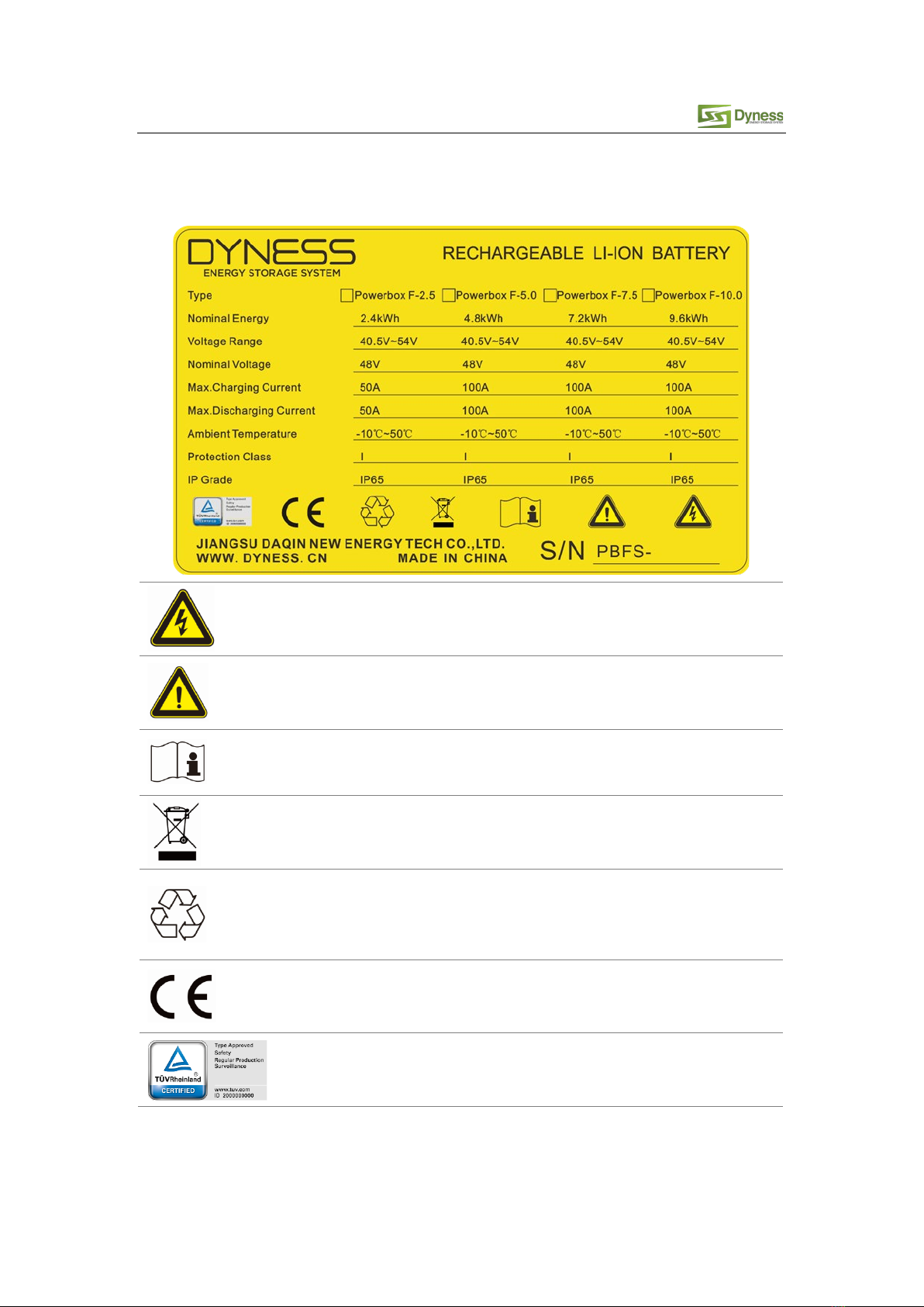
1.3 Product identity definition..................................................................................... 5
2 Product Specification ........................................................................................ 6
2.1 Size and Weight..................................................................................................... 6
2.2 Performance Parameter ........................................................................................ 6
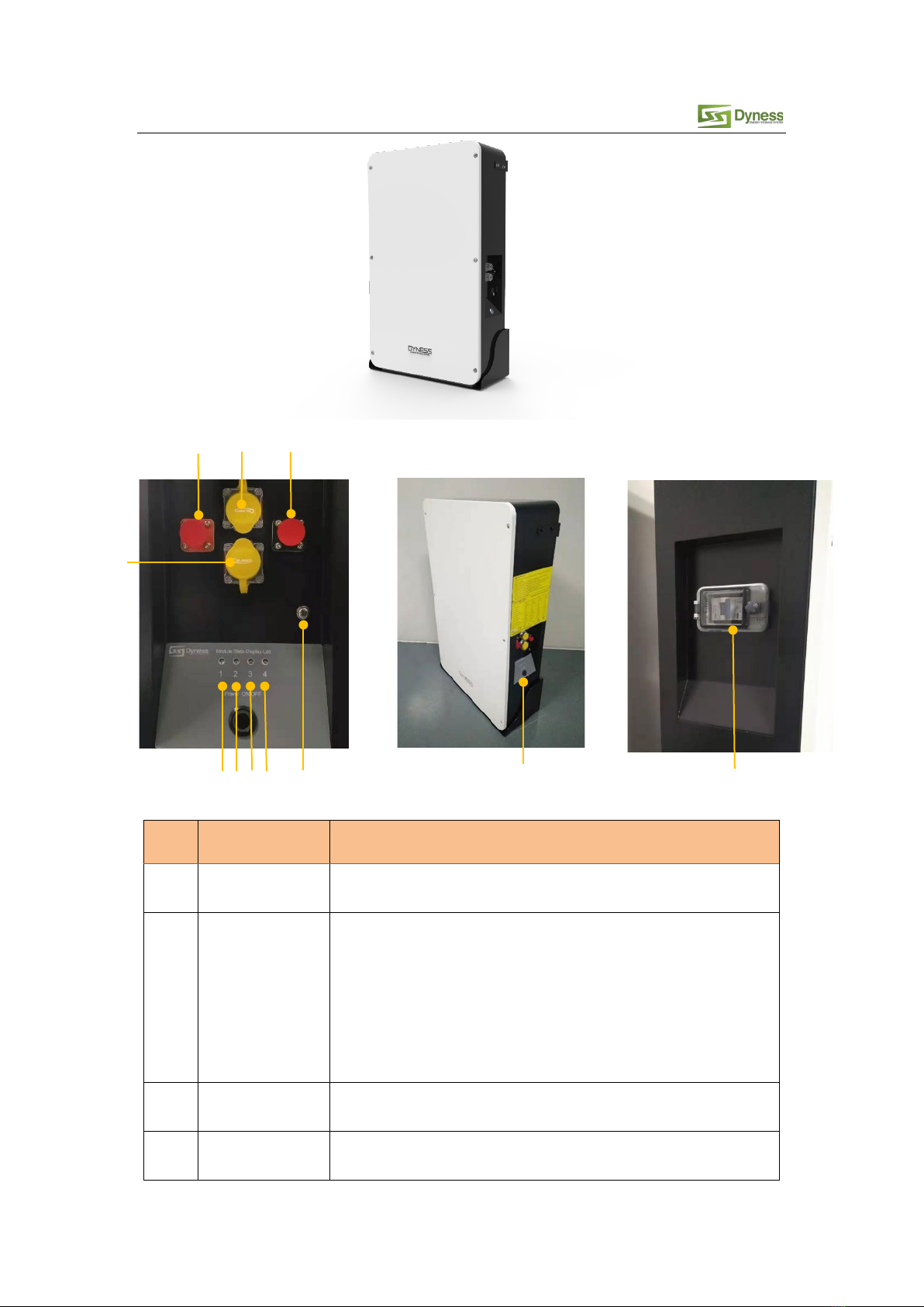
2.3 Interface Definition ............................................................................................... 6
2.4Battery Management System(BMS) ....................................................................... 9
2.4.1 Voltage Protection ................................................................................................. 9
2.4.2 Current Protection................................................................................................. 9
2.4.3 Temperature Protection ........................................................................................ 9
2.4.4 Other Protection .................................................................................................... 9
3 Installation and Configuration......................................................................... 11
3.1 Preparations for installation ................................................................................ 11
3.1.1 Environmental requirements............................................................................... 11
3.1.2 Tools and data ..................................................................................................... 11
3.1.3 Technical preparation .......................................................................................... 12
3.1.4Open the box to have inspection......................................................................... 12
3.1.5 Engineering coordination .................................................................................... 14
3.2 Equipment installation ........................................................................................ 14
3.2.1 Floor installation .................................................................................................. 15
3.2.2 Mounted on the wall ........................................................................................... 16
3.2.3 Electrical installation............................................................................................ 18
3.2.4 Battery module DIP switch definition and description........................................ 22
4 Use, maintenance and troubleshooting........................................................... 29
4.1 Battery system usage and operation instructions................................................. 29
4.2Alarm description and processing ........................................................................ 30
4.2.1 Alarm and countermeasure influence system output......................................... 30
4.2.2 Alarm and countermeasure without affecting the output of the system ........... 30
4.3Analysis and treatment of common faults ........................................................... 31

Powerbox F series User Manual
1
Statement of Law
Copyright of this document belongs to Jiangsu Daqin New Energy Technology Co., Ltd.
No part of this documentation maybe excerpted, reproduced, translated, annotated or duplicated
in any form or by any means without the prior written permission of Jiangsu Daqin New Energy
Technology Co., Ltd. All Rights Reserved.
This product complies withthe design requirements of environmental protection and personal
safety. The storage, use and disposal of the products shall be carried out in accordance with the
product manual, relevant contract or relevant laws and regulations.
Customer can check the related information on the website of Jiangsu Daqin New Energy
Technology Co., Ltd when the product or technology is updated.
Please note that the product can be modified without prior notice.
Manual Version: V1.0
Manual NO.:
Revision History
Revision NO. Revision Date Revision Reason
1.0 2019.02.01 First Published
1.1 2019.08.01 Add parallel connection
description

Powerbox F series User Manual
2
Safety Precautions
Warning
Please do not put the battery into water or fire, in case of explosion or any other situation
that might endanger your life.
Please connect wires properly while installation, do not reverse connect.
To avoid short circuit, please do not connect positive and negative poles with conductor
(Wires for instance).
Please do not stab, hit, trample or strike the battery in any other way.
Please shut off the power completely when removing the device or reconnecting wires
during the daily use or it could cause the danger of electric shock.
Please use dry powder extinguisher to put out the flame when encountering a fire hazard,
liquid extinguisher could result in the risk of secondary disaster.
For your safety, please do not arbitrarily dismantle any component in any circumstances
unless a specialist or an authorized one from our company, device breakdown due to
improper operation will not be covered under warranty.
Caution
We have strict inspection to ensure the quality when products are shipped out, however,
please contact us if case bulging or another abnormal phenomenon.
For your safety, device shall be ground connected properly before normal use.
To assure the proper use please make sure parameters among the relevant device are
compatible.
Please do not mixed-use batteries from different manufacturers, different types and
models, as well as old and new together.
Ambient and storage method could impact the life span and product reliability, please
consider the operation environment abundantly to make sure device works in proper
condition.
For long-term storage, the battery should be recharged once every 6 months, and the
amount of electric charge shall exceed 80% of the rated capacity.
Please charge the battery in 18 hours after it discharges fully and starts over-discharging
protection.
Formula of theoretical standby time: T=C/I (T is standby time, C is battery capacity, I is total
current of all loads).
The surface of the Powerbox cabinet is affixed with a torn invalid label. Therefore, before
opening the cover to change the DIP switch mode, you need to contact DYNESS and inform
the product ID. DYNESS will record this battery ID and authorize the opening operation to be
performed. Except for changing the DIP switch mode, no other operations are allowed. In
the next stage, you can log in to apply for operations directly on the DYNESS website.

Powerbox F series User Manual
3
Contact the authorized dealer or distributor of DYNESS for a new torn invalid sticker after
tearing the original invalid label. When the operation is completed, paste the new one at a
different position.
Preface
Manual declaration
POWERBOX F Lithium Iron Phosphate Battery is external battery module which can storage the
power for home use. When the grid is on, it supplies the home loads and charges the battery
meantime. When grid off, the battery discharges to power up the home loads.
POWERBOX F User manual systematically elaborates device structure, parameters, basic
procedure and method of installation, operation, maintenance.
Safety Statement
Only qualified trained professionals are allowed to install, operate, maintain the device.
Please comply with local safety regulations and operational rules when installation, operation
and maintenance, or it could lead to human injury or device damage.
Mentioned attentions are only as a supplement to local safety regulations.
The seller does not undertake any responsibility for device operations or usage violating
general safety requirements and safety standards.
Sign explanation
Attention should be paid when configuring or operating POWERBOX-F series products, which
follows below format to explain.
Caution
Neglecting the warnings might cause malfunction.

Powerbox F series User Manual
4
1 Introduction
1.1 Brief Introduction
POWERBOX F series lithium iron phosphate home battery is newly power storage products
designed according to market demands, supplies reliable power for all kinds of home
equipment. It is especially suitable for situations with higher temperatures, less space,
higher demand of weight and life span.
POWERBOX F series lithium iron phosphate home battery carries self-developed battery
management system. When the grid is on, it supplies the home loads and charges the
battery meantime. When grid off, the battery discharges to power up the home loads.
Batteries can be paralleled to build a module with more capacity to satisfy the longtime
energy storage demand.
1.2 Product Properties
POWERBOX-F series energy storage product’s anode materials are lithium iron phosphate,
battery cells are managed effectively by BMS with better performance, the systems
features as below:
Comply with European ROHS, Certified SGS, employ non-toxic, non-pollution
environment-friendly battery.
Anode materials are lithium iron phosphate (LiFePO4), safer with longer life span.
Carries battery management system with better performance, possesses protection
function like over-discharge, over-charge, over-current, abnormal temperature.
Self-management on charging and discharging, Single core balancing function.
Intelligent design configures integrated inspection module, with 3 remote functions
(remote-measuring, remote-communicating and remote-controlling).
Flexible configurations allow parallel of multi battery for longer standby time.
Self-ventilation with lower system noise.
Less battery self-discharge, then recharging period can be up to 10 months during the
storage.
No memory effect so that battery can be charged and discharged shallowly.
With wide range of temperature for working environment, -20oC ~ +55 oC, circulation
span and discharging performance are well under high temperature.
Less volume, lighter weight, seal grade up to IP65 embedding design for easier
installation and maintenance.

Powerbox F series User Manual
5
1.3 Product identity definition
FIG1-1 Battery Energy Storage System nameplate
Battery voltage is higher than safe voltage, direct contact with
electric shock hazard.
Be careful with your actions and be aware of the dangers.
Read the user manual before using.
The scrapped battery cannot be put into the garbage can and must
be professionally recycled.
After the battery life is terminated, the battery can continue to be
used after it recycled by the professional recycling organization and
do not discard it at will.
This battery product meets European directive requirements.
This battery product passed the TUV certification test.

Powerbox F series User Manual
6
2 Product Specification
2.1 Size and Weight
Table 2-1 POWERBOX F Series Device Model
Product Series
Specification
Model
Nominal
Voltage
Nominal
Capacity
Dimension
(mm)
Weight
(kg)
IP
Level
POWERBOX POWERBOX F-10 48V200Ah 928×555×210 113 IP65
POWERBOX POWERBOX F-7.5 48V150Ah 928×555×210 91 IP65
POWERBOX POWERBOX F-5.0 48V 100Ah 928×555×210 69 IP65
POWERBOX POWERBOX F-2.5 48V 50Ah 928×555×210 47 IP65
2.2 Performance Parameter
Table 2-2 POWERBOX F performance parameter
Item
POWERBOX F-
2.5
POWERBOX F-
5.0
POWERBOX F-
7.5
POWERBOX F-
10.0
Nominal Voltage(V) 48 48 48 48
Work Voltage Range(V) 42~54 42~54 42~54 42~54
Nominal Capacity(Ah) 50 100 150 200
Nominal Energy(kWh) 2.4 4.8 7.2 9.6
Nominal Power(kW) 0.7 1.5 2.2 2.9
Max Power(kW) 2.4 4.8 4.8 4.8
1S Peak Power(kW) 2.64 5.28 7.92 10.56
1S Peak Current(A) 55 110 165 220
Charging Current(A) 25 50 75 100
Discharge Current(A) 25 50 75 100
2.3 Interface Definition
This section elaborates on interface functions of the front panel of the device.
Figure2-1POWERBOX F the sketch of front interface.

Powerbox F series User Manual
7
Table 2-3 Interface Definition
Item Name Definition
1Positive socket The battery DC output positive pole, which is connected to the
positive pole of the inverter through the cable
2COM IN
When the system is used independently:
The CAN/RS485 socket is connected to the inverter CAN/RS485
interface through the communication cable.
When the system is used in parallel:
This CAN/RS485 communication socket is connected to the COM
OUT interface of the previous Powerbox through communication
cable.
3Negative socket The battery DC output negative pole, which is connected to the
negative pole of the inverter through the cable
4 COM OUT When the system is used independently:
This CAN/RS485 socket is a reservation interface
1
2
3
5
11
10
6
8
7
9
4

Powerbox F series User Manual
8
Item Name Definition
When the system is used in parallel:
This CAN/RS485 communication socket is connected to the COM
IN interface of the next Powerbox through communication cable.
(Factory default CAN communication mode)
5LED1 Module 1 status indicator light
6LED2 Module 2 status indicator light
7LED3 Module 3 status indicator light
8LED4 Module 4 status indicator light
9
Ground
connection point Shell ground connection
10 Reset switch
Press the switch and the battery system turn on.
When the battery is in the nonuse state such as storage,
transportation etc., it needs to be turn off by pressing the Reset
switch button, and the battery system will automatically sleep
after the device without external load and power for 72 hours.
11
DC circuit
breaker Protective circuit
Table 2-4 LED status indicators (Take Powerbox F 10.0 as an example)
State
Protect/
Alarm/
Normal
Led1 Led2 Led3 Led4 Directions
Shut down
off
off
off
off
All off
Stand-by
Normal
●●●●Always on
Alarm
●●●●Always on, Corresponding module
capacity 5%<SOC≤10%
Protection ●●●●
Flashing, (Corresponding module
capacity, 0%≤SOC≤5%/Low voltage
alarm / Over-discharge protection /
Over-charge protection / Over-current
alarm or protection / Hardware failure /
Temperature abnormality, etc.)
Charging/disc
harging
Normal
●
●
●
●
Always on
Alarm ●●●●
Always on, Corresponding module
capacity 5%<SOC≤10%, Over-charged
alarm.
Protection ●●●●
flashing, (Corresponding module
capacity, 0% ≤SOC≤5% / Low voltage
alarm / Over-discharge protection /
Over-charge protection / Over-current
alarm or protection / Hardware failure /
Temperature abnormality, etc.)

Powerbox F series User Manual
9
2.4 Battery Management System(BMS)
2.4.1 Voltage Protection
Discharging Low Voltage Protection:
When any battery cell voltage is lower than the Rated protection value or total voltage below 42V
during discharging, the over-discharging protection starts, and the battery buzzer makes an alarm
sound. Then battery system stops supplying power to the outside. When the voltage of each cell
recovers to rated value and total voltage restored to above 45V, the protection is released.
Charging Over Voltage Protection:
When charging, the system stops charging when the total voltage of the battery pack is higher than
54.75V or the voltage of any single cell reaches the protection value. When the total voltage
returns to below 52V and the cell voltage returns to below the rated protection value, the
protection is released.
2.4.2 Current Protection
Over Current Protection in Charging:
When the charging current is greater than the protection value 55A, the battery buzzer alarms and
the system stops charging. After the system delays the rated time for 1min, the protection is
released.
Over Current Protection in Discharging:
When the discharge current is greater than the protection value 55A, the battery buzzer alarms
and the system stops discharging. After the system delays the rated time for 1min, the protection
is released.
Note:
The buzzer sound alarm setting can be manually turned off on the background software, and the
factory default is on.
2.4.3 Temperature Protection
Less/Over temperature protection in charging:
When battery’s temperature is beyond range of 0oC~+55oC during charging, temperature
protection starts, device stops charging. The protection is released when it recovers to rated return
range.
Less/Over temperature protection in discharging:
When battery’s temperature is beyond range of -20oC ~+55oC during discharging, temperature
protection starts, device stops supplying power to the outside. The protection is released when it
recovers to rated return range.
2.4.4 Other Protection
Short Circuit Protection:

Powerbox F series User Manual
10
When the battery is activated from the off state, if a short circuit occurs, the DC circuit breaker will
act first. If the DC circuit breaker does not operate, the BMS will start the short circuit protection
function and cut off the external voltage output.
Self Shutdown:
When device connects no external loads for over 72 hours, device will dormant standby
automatically.
Caution
The maximum working current of the load which needs to be powered should be less than the
maximum discharge current capacity of the battery system.

Powerbox F series User Manual
11
3 Installation and Configuration
3.1 Preparations for installation
Safety Requirement
This system can only be installed by personnel who have been trained in the power supply system
and have sufficient knowledge of the power system.
The safety regulations and local safety regulations listed below should always be followed during
the installation.
All circuits connected to this power system with an external voltage of less than 48V
must meet the SELV requirements defined in the IEC60950 standard.
If operating within the power system cabinet, make sure the power system is not
charged. Battery devices should also be switched off
Distribution cable wiring should be reasonable and has the protective measures to
avoid touching these cables while operating power equipment.
when installing the battery system, must wear the protective items below:
The isolation gloves Safety goggles Safety shoes
3.1.1 Environmental requirements
Working temperature: -20 oC ~ +55 oC
•Charging temperature range is 0oC~+55 oC,
•Discharging temperature range is -20 oC ~+55 oC
Storage temperature: -10 oC ~ +35 oC
Relative humidity: 5% ~ 85%RH
Elevation: no more than 4000m
Operating environment: Indoor or outdoor installation, sites avoid the sun and no wind,
no conductive dust and corrosive gas.
And the following conditions are met:
•Installation location should be away from the sea to avoid brine and high humidity
environment.
•The ground is flat and level.
•There is no flammable explosive near to the installation places.
•The optimal ambient temperature is 15oC ~ 30 oC
•Keep away from dust and messy zones
3.1.2 Tools and data

Powerbox F series User Manual
12
Hardware tool
Tools and meters that may be used are shown in table 3-1.
Table 3-1 Tool instrument
Name
Screwdriver (word, cross) AVO meter
wrench clamp meter
Inclined pliers Insulating tape
Needle nose pliers The thermometer
Clip forceps wrist strap
Wire stripper AVO meter
Electric drill Tape
3.1.3 Technical preparation
Electrical interface check
Devices that can be connected directly to the battery can be user equipment, power
supplies, or other power supplies.
Confirm whether the user equipment, the PV equipment or other power supply
equipment has the DC standby interface, and measure whether the output voltage
of the standby interface meets the requirements of the voltage range of table 2-2
Verify that the maximum discharge current capacity of the user equipment, the PV
equipment or other power supplies, the DC standby interface, and the maximum
discharge current shall be greater than the maximum charging current of the
products used in table 2-2.
If the user equipment DC prepared interface maximum discharge capacity is less than
the maximum charging current products using table 2-2, the user interface should
have the power equipment of DC current limiting function, give priority to ensuring
the normal work of user equipment.
The security check
Firefighting equipment should be provided near the equipment, such as portable dry
powder fire extinguisher.
Automatic fire fighting system shall be provided for the case where necessary.
No flammable, explosive and other dangerous articles are placed beside the battery.
3.1.4 Open the box to have inspection
When the equipment arrives at the installation site, loading and unloading should
be carried out according to the rules and regulations, so as to prevent from being
exposed to sun and rain.
Before unpacking, the total number of packages shall be indicated according to the
shipping list attached to each package, and the case shall be checked for good
condition.

Powerbox F series User Manual
13
In the process of unpacking, handle with care and protect the surface coating of the
object.
Open the package, the professional installation person should read the technical
documents, verify the list, according to the configuration table and packing list,
ensure objects are complete and intact. If the internal packaging is damaged, it must
be inspected and recorded in detail.
Packing list is as follows:
Battery×1
Battery bottom bracket ×1
Support bracket ×2
M6 bolt ×8
Fixing battery box with
battery bracket
Power cable ×2
connect battery with inverter
Communication cable
M6 3 sets of combined screws
x 1 (Already installed on the
system cabinet)
Ground wiring
Expansion screw ×8
Positioning cardboard×1

Powerbox F series User Manual
14
User manual ×1
3.1.5 Engineering coordination
Attention should be paid to the following items before construction:
Power line specification.
The power line specification shall meet the requirements of maximum discharge
current for each product.
Mounting space and bearing capacity.
Make sure that the battery has enough room to install, and that the battery rack and
bracket have enough load capacity.
Wiring.
Make sure the power line and ground wire are reasonable. Not easy to short-circuit,
water and corrosion.
3.2 Equipment installation
The wall for battery installation shall be solid brick or cement wall with strong bearing capacity and
wall thickness no less than 100mm.
Mounting space requirements:
Floor installation Mounted on the wall installation
Table 3-2 Installation steps

Powerbox F series User Manual
15
Step1 System outage Ensure that the battery is in a shutdown state
Step 2 Mechanical
installation
1. Hanger mounting
2.Equipment installation
Step3 Electrical
installation
1. Connect the ground cable
2 Electrical installation
3.Connect inverter
4.Communication interface connection
3.2.1 Floor installation
When the battery system is placed directly on the ground, a fixed support must be used
to fix the top of the battery box with the wall.
3.4 holes with diameter of 10mm shall
be opened on the wall with electric
drill according to the marked position,
and the hole depth shall be greater
than 70mm to fit the expansion bolts
of M6.
1.Use the positioning cardboard
provided with the goods to draw
the screw hole positions on the
wall, as shown in the four holes
on the left.
2.The bottom of board must be good
connection with the ground level
while drawing the holes.

Powerbox F series User Manual
16
3.2.2 Mounted on the wall
The following accessories need to be added when mounted the battery on the wall.
Battery bottom bracket ×1 Expansion screw ×4
Installation procedure
4.
Fixing the expansion bolt M6 into the
bottom of the hole on the wall.
5.Use the M6 bolt to fixing the Support
bracket to the wall and control the
torque at 6NM.
6.
Carry the battery box to the
installation site, and place it about
15mm away from the vertical wall
surface, fixing the Support bracket
and the upper part of the battery
box with M6 bolts.

Powerbox F series User Manual
17
1.Use the positioning cardboard provided
with the goods to draw the screw hole
positions on the wall, as shown in the
four holes on the left.
2.The cardboard must be perpendicular
to the ground while drawing the holes.
3.The bottom of the cardboard is about
300mm from the ground.
4. According to the position of the
mark, 8 holes in diameter 10mm
and depth of more than 70mm are
hit on the wall with an electric drill,
which are used for fitting expansion
bolt M6.
5.
Fixing the expansion bolt M6 into the
bottom of the hole on the wall, and fix
the Support bracket and Battery bottom
bracket on the wall with M6 bolts,
twisting force keeps 6NM.
6. Carry or hoist the battery box to the
installed Battery bottom bracket.
Fixing the Support bracket and the
upper part of the battery box with
M6 bolts, twisting force keeps 6NM.
Then fixing the Battery bottom
bracket and the bottom part of the
battery box with M6 bolts, twisting
force keeps 6NM.

Powerbox F series User Manual
18
3.2.3 Electrical installation
Before connecting the power cables, using multimeter to measure cable continuity, short
circuit, confirm positive and negative, and mark well the cable labels.
Measuring methods:
Switch off cables: select the buzzer and use the probe to measure the ends of the
same color cable. If the buzzer calls, it means the cable is available.
Short circuit judgment: choose multimeter resistor file, probe the same end of
positive and negative pole, if the resistor shows infinity, means that the cable is
available.
After visual testing of power line is connected well, the positive and negative poles
of the battery shall be connected respectively to the positive and negative poles of
another device.
Connect the battery box to the ground cable
Customer needs to prepare a M6 OT terminals and ground cables. Ground the battery
shell as shown below. The sectional area of the grounding cable shall be at least 6mm2
and the bolt locking torque is 6NM.
Connected inverter
Note:
If there is any question during installation, please contact your dealer to avoid damage to
the equipment.
When the system is used independently:
Note: Before installation, please confirm whether the DIP switch mode of No. 1 module
in POWERBOX is correct according to the inverter used. For specific dialing methods,
please refer to “3.2.4 Battery module DIP switch definition and description.” Except for
the inverter specified by the customer's special requirements, the factory default DIP
switch mode of Module No.1 is DIP Switch mode 1 (ADD: 0010). If the inverter is
equipped with other DIP switch mode, open the cover and Set DIP switch mode of the
Other manuals for POWERBOX F Series
1
This manual suits for next models
4
Table of contents
Other Dyness Camera Accessories manuals
Popular Camera Accessories manuals by other brands

Westcott
Westcott 1856 Setup instructions

Panasonic
Panasonic DMW-DCC6 operating instructions

Gates Underwater Products
Gates Underwater Products PRO ACTION Setup, use and care guide

Sony
Sony FA-CC1AM operating instructions

Merlin
Merlin ProShot Gimbal instruction manual

TeAx Technology
TeAx Technology ThermalCapture 2.0 Mounting instructions