B4850 ESS Unit User Manual
I
Content
STATEMENT OF LAW ..................................................................................................................................... 1
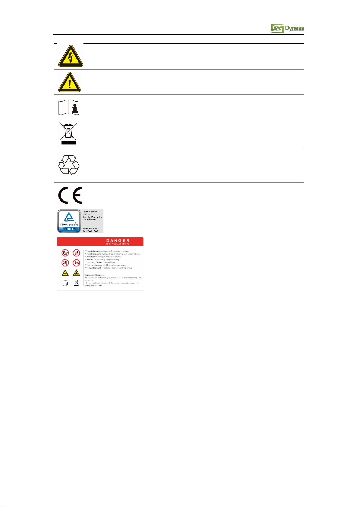
SAFETY PRECAUTIONS................................................................................................................................... 2
PREFACE.......................................................................................................................................................... 3
1 INTRODUCTION.......................................................................................................................................... 4
1.1 BRIEF INTRODUCTION.............................................................................................................................................4
1.2 PRODUCT PROPERTIES............................................................................................................................................4
1.3 PRODUCT IDENTITY DEFINITION ..............................................................................................................................4
2 PRODUCT SPECIFICATION ......................................................................................................................... 6
2.1 SIZE AND WEIGHT...................................................................................................................................................6
2.2 PERFORMANCE PARAMETER...................................................................................................................................6
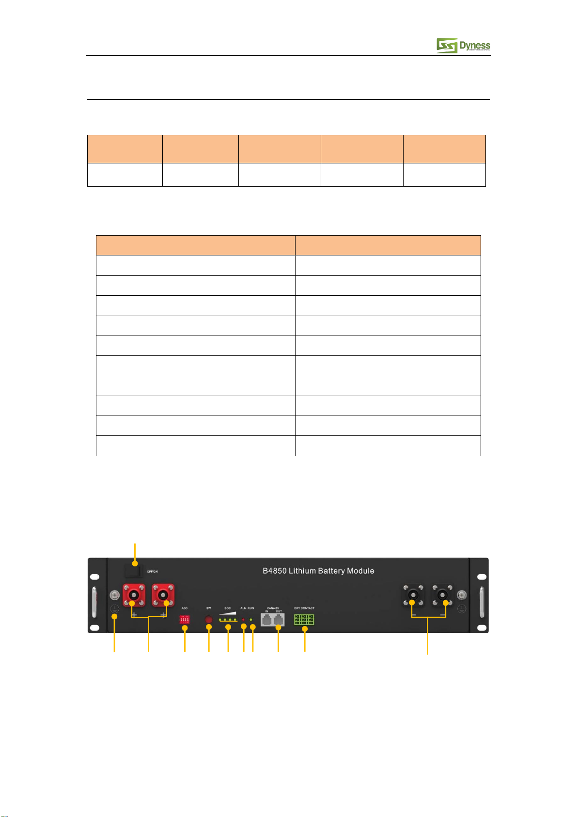
2.3 INTERFACE DEFINITION ...........................................................................................................................................6
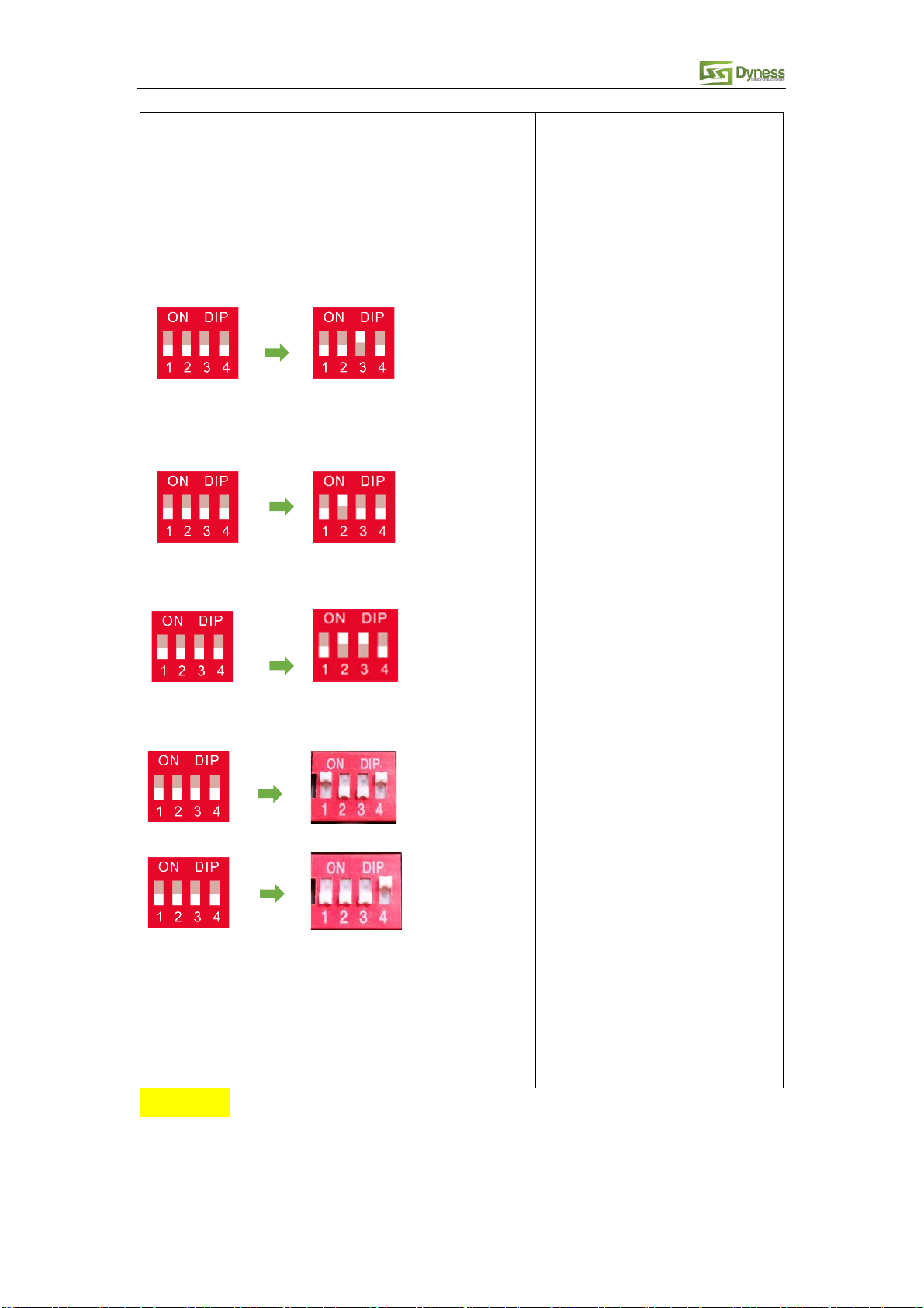
2.3.1 DIP switch definition and description
...................................................................................................7
2.4 BATTERY MANAGEMENT SYSTEM(BMS)............................................................................................................ 10
2.4.1 Voltage Protection
................................................................................................................................ 10
2.4.2 Current Protection
................................................................................................................................. 10
2.4.3 Temperature Protection
...................................................................................................................... 11
2.4.4 Other Protection
.................................................................................................................................... 11
3 INSTALLATION AND CONFIGURATION .................................................................................................. 11
3.1 READY FOR INSTALLATION ................................................................................................................................... 11
3.1.1 Environmental requirements
.............................................................................................................. 12
3.1.2 Tools and data
....................................................................................................................................... 12
3.1.3 Technical preparation
.......................................................................................................................... 12
3.1.4 Unpacking inspection
........................................................................................................................... 13
3.1.5 Engineering coordination
.................................................................................................................... 14
3.2EQUIPMENT INSTALLATION.................................................................................................................................. 15
3.2.1 Installation preparation
........................................................................................................................ 15
3.2.2 Mechanical installation
......................................................................................................................... 15
3.2.3 Electrical installation
............................................................................................................................ 16
3.2.4 Battery parameter settings on the inverter
.................................................................................... 18
3.2.5 Register on the website after installation
....................................................................................... 18
4 USE, MAINTENANCE AND TROUBLESHOOTING ................................................................................... 19
4.1 BATTERY SYSTEM USAGE AND OPERATION INSTRUCTIONS ..................................................................................... 19
4.2ALARM DESCRIPTION AND PROCESSING............................................................................................................... 20
4.3ANALYSIS AND TREATMENT OF COMMON FAULTS ............................................................................................... 21