8Troubleshooting
Troubleshooting
Caution: Do not open the open the receiver case or
microphone housing. There are no user serviceable parts
inside.
Symptom Possible solution
Receiver is turned on, but POWER
indicator does not light.
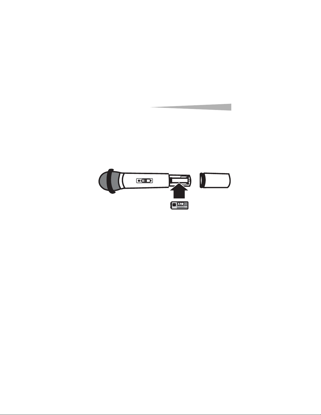
• Make sure that the batteries are installed correctly.
You must match the + and – symbols on the batteries
with the + and – symbols in the battery
compartment.
• Make sure that the batteries have a charge. Change
the batteries, if necessary.
The AUDIO indicator lights when
speaking into the microphone,
but there is no sound.
• Make sure that the volume control on the amplifier is
not set too low.
• Make sure that the audio cable is connected securely
to the receiver and amplifier.
The signal range is too small. • Make sure that the antenna is fully extended.
• Make sure that the batteries are installed correctly.
You must match the + and – symbols on the batteries
with the + and – symbols in the battery
compartment.
• Make sure that the batteries have a charge. Change
the batteries, if necessary.
• Make sure that the receiver or microphone are not
located within a magnetic field.
Sound quality is poor. • Make sure that the batteries are installed correctly.
You must match the + and – symbols on the batteries
with the + and – symbols in the battery
compartment.
• Make sure that the batteries have a charge. Change
the batteries, if necessary.
• Make sure that no other devices in the area are
operating on the same frequency as your wireless
microphone. Devices using the same frequency
should be at least 328 feet (100 meters) apart.