logo
Brands
  1. Home
  2. •
  3. Brands
  4. •
  5. Dyson
  6. •
  7. Plumbing Product
  8. •
  9. Dyson AB 06 User manual

Dyson AB 06 User manual

Other manuals for AB 06

1

Other Dyson Plumbing Product manuals

Dyson Airblade Wash+Dry User manual

Dyson

Dyson Airblade Wash+Dry User manual

Dyson AB09 User manual

Dyson

Dyson AB09 User manual

Dyson Airwrap User manual

Dyson

Dyson Airwrap User manual

Dyson Airblade Tap User manual

Dyson

Dyson Airblade Tap User manual

Dyson AB09 User manual

Dyson

Dyson AB09 User manual

Dyson Airblade wD05 User manual

Dyson

Dyson Airblade wD05 User manual

Popular Plumbing Product manuals by other brands

Weka 506.2020.00E ASSEMBLY, USER AND MAINTENANCE INSTRUCTIONS

Weka

Weka 506.2020.00E ASSEMBLY, USER AND MAINTENANCE INSTRUCTIONS

American Standard DetectLink 6072121 manual

American Standard

American Standard DetectLink 6072121 manual

Kohler K-6228 Installation and care guide

Kohler

Kohler K-6228 Installation and care guide

Uponor Contec TS Mounting instructions

Uponor

Uponor Contec TS Mounting instructions

Pfister Selia 49-SL Quick installation guide

Pfister

Pfister Selia 49-SL Quick installation guide

Fortis VITRINA 6068700 quick start guide

Fortis

Fortis VITRINA 6068700 quick start guide

Kohler K-12183 Homeowner's guide

Kohler

Kohler K-12183 Homeowner's guide

Maxxus MX-M206-01 instruction manual

Maxxus

Maxxus MX-M206-01 instruction manual

Viega Prevista Pure 8512 Instructions for use

Viega

Viega Prevista Pure 8512 Instructions for use

Kohler Centerset K-15240 Homeowner's guide

Kohler

Kohler Centerset K-15240 Homeowner's guide

Viega Prevista Dry 8522.33 Instructions for use

Viega

Viega Prevista Dry 8522.33 Instructions for use

Sanela Lema SLP 59RB Instructions for use

Sanela

Sanela Lema SLP 59RB Instructions for use

Elkay EDF15AC Installation, care & use manual

Elkay

Elkay EDF15AC Installation, care & use manual

Hans Grohe AXOR Citterio E 36702000 Instructions for use/assembly instructions

Hans Grohe

Hans Grohe AXOR Citterio E 36702000 Instructions for use/assembly instructions

baliv WT-140 manual

baliv

baliv WT-140 manual

Kohler Mira Eco Installation & user guide

Kohler

Kohler Mira Eco Installation & user guide

BELLOSTA romina 0308/CC Installation instruction

BELLOSTA

BELLOSTA romina 0308/CC Installation instruction

Bristan PS2 BAS C D2 Installation instructions & user guide

Bristan

Bristan PS2 BAS C D2 Installation instructions & user guide

https://manuals.online logo
https://manuals.online logoBrands
  • About & Mission
  • Contact us
  • Privacy Policy
  • Terms and Conditions

Copyright 2025 Manuals.Online. All Rights Reserved.

1
Installation guide
2
IMPORTANT SAFETY INSTRUCTIONS
READ BEFORE PROCEEDING FURTHER.
RETAIN FOR FUTURE USE.
WARNING
All electrical installation and repair work should be carried out by a qualified electrician or
Dyson Service Engineer in accordance with current local codes or regulations.
Filter change should be carried out by a qualified person.
WARNING
Risk of electric shock! If casing is removed or handled improperly the internal components of the
unit may cause harm or become permanently damaged.
TO REDUCE THE RISK OF FIRE, ELECTRIC SHOCK, OR INJURY TO PERSONS,
OBSERVE THE FOLLOWING:
BEFORE INSTALLATION
Before beginning any installation work you must confirm the following.
WIRING
• Check that the electrical supply corresponds to that shown on the rating plate. If the unit is connected
to any electrical supply other than stated on the rating plate of the unit, permanant damage or
improper/unsafe operation of the hand dryer may result.
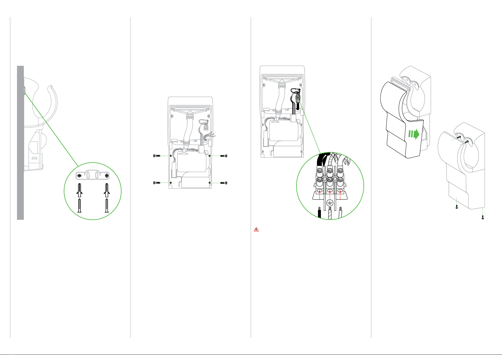
• A means for all-pole disconnection must be incorporated into fixed wiring, in accordance with local
wiring regulations.
• The unit must be earthed.
• When connecting the unit to the electricity supply use cable in accordance with all federal, state and
local laws and applicable codes and standards, including fire-rated construction.
• Ensure that the conduit and wires are long enough to connect to the backplate and the terminal block.
SAFETY
• Isolate the power before installation or service.
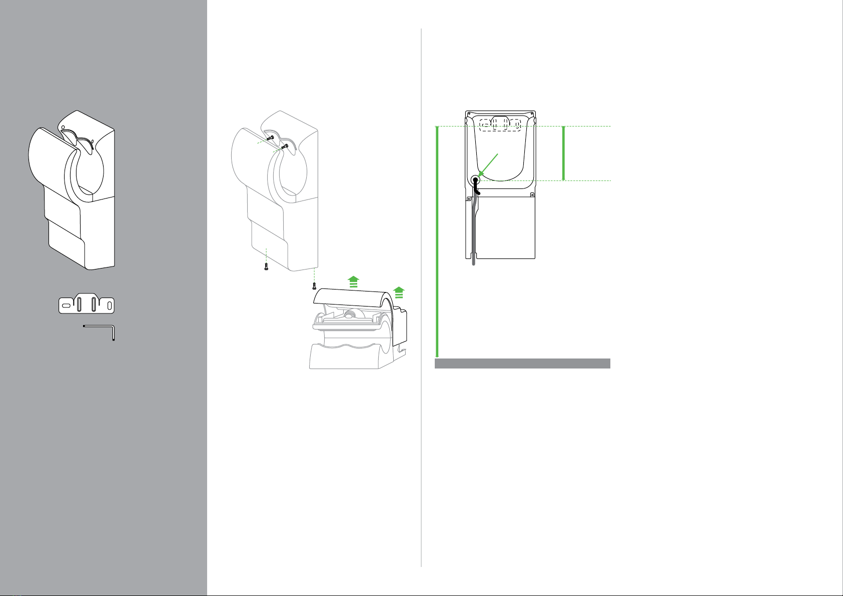
INSTALLATION
• Make sure that the unit is installed in compliance with all building codes and/or regulations.
• The unit must be mounted on a flat vertical wall capable of supporting the full weight of the unit.
• Use fixings as specified in this installation guide.
• Ensure no pipe work (gas, water, air) or electrical cables, wires or ductwork are located directly behind
the drilling/mounting area.
• If you are installing this tap hand dryer in a food handling or food manufacturing environment, please
contact the Dyson Helpline for the specialist installation guide that supports this.
• Dyson recommends the use of protective clothing, eyeware and materials when installing/repairing as
necessary.
• To avoid damage to the fascia surface during installation, store the fascia in the original packaging
until it is needed.
LOCATION
• The unit is designed for dry, internal location only.
• Consult local and national accessibility codes and regulations for relevant installation guidelines.
Conformity and compliance is the responsibility of the installer.
• Ensure the required electrical supply is available for later connection.
• If you are installing this tap hand dryer in a food handling or food manufacturing environment, please
contact the Dyson Helpline for the specialist installation guide that supports this.
IMPORTANT
• Please refer to the Dyson Owners Manual for details of the guarantee.
3
4
WARNING
Use caution when removing the fascia. The fascia
may have sharp edges/corners which may cut or
cause harm.
1. Remove the (4) tamper-proof screws from the
unit with the service tool provided. Store safely.
2. Note: Some models have a small door at the
base of the machine. Remove the (1) tamper-
proof screw with the service tool.
3. Remove the fascia as shown.
1. Select a location that will allow accessibility
to the unit and proper clearance from
surroundings and floor. Allow at least 200mm
clearance under the unit.
2. Recommended heights are shown, but may
need to be adjusted for each individual
installation.
Cable
Connect the electrical supply using approved
flexible or solid conduit and electrical fittings.
Ensure that the flexible or solid conduit and
wires are of sufficient length to make the
necessary connection to the backplate
and the terminal block.
990mm adult male height.
915mm adult female height.
815mm child/wheelchair user height UK
840mm child/wheelchair user height ANZ
Height measurements are from the floor.
235mm
Cable entry:
The cable entry point is on the rear of the
backplate. The exterior route to the cable
entry point can be either:
1. From the wall: directly into the cable
entry point.
2. From the base: via the exterior cable channel
in the backplate and into the cable entry point.
Ensure the cable is not trapped between the
backplate and the wall.
12
Remove fascia.In this box. Selecting the height.
Main unit x 1
Wall bracket x 1
Service tool x1
Fixings
To install this unit you will need (6) screws, toggle
or masonry bolts and appropriate fittings for the
wall type and weight of the unit (recommended
minimum size of 7mm).
Cable entry
point
Rear view
5
1. Hook the backplate onto the wall bracket. Use
the backplate to mark the locations for the four
fixing points. Remove the backplate from the
bracket and drill the four holes.
NOTE: For easier access to the lower fixing screw,
temporarily remove the filter.
CAUTION: Do not use the backplate as a guide
when drilling.
2. Hook the backplate onto the wall bracket.
3. Install the electrical cable via the cable gland.
4. Ensure the cable sits in the pre-formed channel.
in the exterior of the backplate.
5. Secure the backplate to the wall using the
appropriate fixings.
WARNING: Risk of electric shock!
1. Secure the live, neutral and earth wires
into the correct terminal block locations as
indicated on the terminal block casing.
2. Verify the connections are correct before
proceeding.
3. Tighten the cable gland.
1. Secure the bracket to the wall using the
appropriate fixings for the wall type and the
weight of the main unit. Ensure the bracket
is level.
1. Carefully replace the fascia as illustrated.
2. Do not trap the cable when attaching
the fascia.
3. Make sure that the fascia is mounted
flush before tightening the screws.
4. Insert the anti-tamper screws into
the fascia as illustrated – top screws first,
hand-tight, followed by the lower screws.
Then secure all screws.
5. Test the unit for correct operation.
NOTE: Do not use sealant when fixing
the unit to the wall.
3 4 5 6
Mount bracket to wall. Secure backplate to wall. Connect to terminal. Attach fascia.
L N
6
7
8
Dyson Customer Care Helpline
www.dysonairblade.com
JN. 55280 PN.63206-01-04 21.03.13
UK 0800 345 7788
ROI 01 401 8300.
AU 1800 426 337
NZ 0800 397 667
SG 7000 435 75 46
HACCP International Non-food certification Mark is the registered trademark of HACCP International.
The NSF logo is a registered trademark of NSF International Corporation.
NSF PROTOCOL P335
HYGIENIC COMMERCIAL
HAND DRYERS