manuals.online logo
Brands
  1. Home
  2. •
  3. Brands
  4. •
  5. Helvex
  6. •
  7. Plumbing Product
  8. •
  9. Helvex 310-32 User manual

Helvex 310-32 User manual

1-06-0595-7
Medidas Generales / General Dimensions
INSTALLATION GUIDE
GUÍA DE INSTALACIÓN
Fluxómetro de Pedal Expuesto para Taza Flux, Spud de 38
mm, 4,8 LPD
Exposed Pedal Flushometer for Flux Bowl, 1 1/2" Spud,
1,26 GPF
310-WC-4.8
Fluxómetro de Pedal Expuesto para Taza Flux Nao ó Nao17,
Spud de 38 mm, 3,5 LPD
Exposed Pedal Flushometer for Nao or Nao17 Flux Bowl, 1
1/2" Spud, 0,92 GPF
310-38-3.5
Fluxómetro de Pedal Expuesto para Taza Flux, Spud de 32
mm ó 38 mm, 6 LPD
Exposed Pedal Flushometer for Flux Bowl, 1 1/4" or 1 1/2"
Spud, 1,58 GPF
310-32,310-38
Hola soy Fluxy, te
ayudaré a instalar
tu producto.
Hi I'm Fluxy, I'll
help you to install
your product.
Herramientas y Materiales Recomendados / Recommended Tools and Materials
desarmador plano teflón
plumber’s tape
llave inglesa
adjustable
wrench
cortador de tubo
pipe cutter
Para disminuir el riesgo de lesiones o daños a la propiedad, lea todas las instrucciones antes de instalar el
producto. Utilice gafas de seguridad. En obras de construcción, instalación, modificación, ampliación y
reparación deben cumplir con el reglamento de construcción y obras de su localidad. El producto ilustrado
puede sufrir cambios de aspecto como resultado de la mejora continua a la que está sujeto.
Agradecemos su elección por los productos HELVEX.
Estamos seguros de que su confiabilidad por el producto excederá sus más altas expectativas, cuya
funcionalidad, estética, durabilidad, respaldo integral y alta calidad le otorgarán plena satisfacción por años,
reflejando el compromiso con la calidad, innovación y el medio ambiente que forman parte de Helvex.
To reduce the risk of injury or property damage, read all instructions before installing the product. Please
remember to use safety glasses. In construction, installation, alteration, extension and repair, the rules of
constructions must be applied. As result of continuous improvement, the illustration product may change in
appearance.
ADVERTENCIA / WARNING
Esta Guía de Instalación Aplica al Producto en Cualquier Acabado
This Installation Guide Applies to the Product in any Finishing
Thank you for choosing HELVEX products.
We are confident that the product reliability will exceed your maximum expectations. The functionality,
aesthetics, durability, quality and support will grant you full satisfaction for years, it is Helvex commitment to
the quality, innovation and the environment.
Cada metro de altura de
su producto a la base
del tinaco equivalen a
(0,1 kg/cm²) [1,42 PSI].
Every meter of height of
your product to the base
of the tube is equivalent
to (0,1 kg/cm²) [1,42
PSI].
Requerimientos de Instalación
Installation Requirements
310-32
Requerimientos de Instalación
Installation Requirements
Modelo / Model Mínima / Minimum Máxima / Maximum
kg/cm² PSI kPa kg/cm² PSI kPa
310-38-3.5
1,0 14,2 98,06 6,0 85,3 588,3
310-38
2,0 28,4 196,1 6,0 85,3 588,3
310-WC-4.8
1
*A Verificar la dimensión de
acuerdo a la ubicación del W. C.
* A Check the dimension according
to the location of the W. C.
adaptador
(no incluido)
adapter
(not included)
*A
60 cm
(23,6”)
Nota: La tubería debe ser de Ø 32 mm
desde la alimentación.
Note: The pipe diameter should
be Ø1 ¼" from the supply.
tubería de alimentación
Ø 32 mm (no incluida)
Ø 1 ¼" supply pipe
(not included)
reducción campana de
Ø 32 a 25,4 mm (no incluida)
Ø 1 ¼" - 1" reducing coupling
(not included)
tubo Ø 1” (no incluido)
Ø 1" pipe (not included)
cámara de aire con tubo de Ø 32 mm
air chamber with Ø 1 ¼” pipe
tubo Ø 32 mm
(no incluido)
Ø 1 ¼” pipe
(not included)
[email protected]
Original Spare Parts:
Consultancy and Technical
(52) 55 53 33 94 31
(52) 55 53 33 94 00
Refacciones Originales:
Asesoría y Servicio Técnico:
Ext. 5913, 5068 y 4815
Service:
(52) 55 53 33 94 21
[email protected]
www.refaccioneshelvex.com.mx
Para el correcto funcionamiento de éstos productos, se recomiendan las sig. presiones:
For the correct functioning of these products, the recommended water pressure is:
slotted screwdriver
310-38
310-38-3.5
310-WC-4.8
310-32
2
2pared con
acabado final
finished wall
20 cm
(7,8”)
*13 cm
(5,1”)
10 cm
(3,9”)
24 cm
(9,4”)
NPT
FFL
*22,5 cm
(8,8”)
(Nivel de Piso Terminado)
(Finished Floor Level)
33 cm
(12,9”)
pared con
acabado final
finished wall
Componentes del Producto / Product Components
3
Instalación General / General Installation
* Medidas recomendadas
* Recommended dimensions
16
15
15
Para spud de Ø 32 mm / For Ø spud1 ¼”
No. DESCRIPCIÓN
1 Cúpula
2 Empaque
3 Émbolo Armado
4 Rondana Vulcanizada
5 Chapetón
6 Llave de Retención
7 O´ring
8 Pedal con Estopero Armado
9 Empaque 38 mm
10 Rondana 38 mm
11 Tuerca Spud
12 Codo de 32 mm
13 Niple de Pedal 32 mm
14 Chapetón
Para spud de Ø 38 mm / For Ø spud1 ½”
DESCRIPTION
Cap
Gasket
Piston
Vulcanized Washer
Escutcheon
Stop Valve
O´ring
Pedal
1 ½” Gasket
1 ½” Friction Ring
1 ½” Spud Nut
1 ¼” Elbow
1 ¼” Pedal Nipple
Escutcheon
310-WC-4.8
310-32
Chapetón para Spud 32 mm
Empaque, Rondana y Tuerca Spud 32 mm
Codo de 32mm
1 ¼” Large Spud Escutcheon
1 ¼” Gasket, Friction Ring and Nut
1 ¼” Elbow
1
2
3
4
7
9
10
11
6
8
13
12
310-38-3.5
18
19
18
18
19
20
Desarme el fluxómetro. / Disassemble
the flushometer.
4
tuerca
nut
5
para spud 32 mm usar conector
1¼-11½ NPSM, para spud 38 mm usar
conector 1½-11½ NPSM
to 32mm spud used 1¼-11½ NPSM
connector to 38mm spud used
1½-11½ NPSM connector adaptador (no incluido)
1-11 ½ - NPT
1-11 ½ - NPT adapter
(not included)
paso muro de conexión a descarga, verificar
diámetro del niple Ø 50,8mm Max.
step discharge wall connection, check
the diameter Ø 2" nipple Max.
Nota: Coloque teflón en las conexiones roscadas
Note: Apply plumber’s tape around the threaded connections
*A
cuerpo armado
assembly body
llave de
retención
stop valve
Coloque la llave de retención y el adaptador (no incluido) con respecto a la ubicación del
inodoro. / Place the stop valve and adapter (not included) according to the location of the toilet.
llave de
retención
stop valve chapetón
escutcheon
310-32
Émbolo Color Azul 6 LPD
1,5 GPF Blue Color Piston
310-38
310-38-3.5
Émbolo Color Naranja 3,5 LPD
0,9 GPF Orange Color Piston
310-38-4.8
Émbolo Color Verde 4,8 LPD
1,2 GPF Green Color Piston
310-38
*A Verificar la dimensión de
acuerdo a la ubicación del inodoro.
*A Check the dimension according
to the location of the toilet.
15
16
17
Chapetón para Spud 38 mm
Empaque, Rondana y Tuerca Spud 38 mm
Codo de 38 mm
1 ½” Large Spud Escutcheon
1 ½” Gasket, Friction Ring and Nut
1 ½” Elbow
5
14
16
17
19
20
3
8
7Inserte el cuerpo armado y apriete firmemente las tuercas. / Insert
the assembly body and tighten firmly the nuts.
tuerca
nut
empaque
gasket
rondana
friction ring
tuerca
nut
codo
elbow
Arme el codo según el modelo. / Assembly the elbow according to the model.
6
chapetón
escutcheon
niple
nipple
codo
elbow
Enrosque el niple al codo e inserte el chapetón al niple y enrosque
al conector hembra 1 ¼ - 11 ½ NPT del muro e inserte la tuerca, la
rondana y el empaque. / Screw the nipple to the elbow to insert the
escutcheon nipple and screw socket 1 ¼ - 11 ½ NPT wall and
insert the nut, the friction ring and the gasket.
chapetón
escutcheon
empaque
gasket
rondana
friction ring
tuerca
nut
niple con codo
nipple with elbow
Mod. 310-32
Mod. 310-38,
Mod. 310-38-3.5
Mod. 310-WC-4.8
para spud
de 38mm
/ spud 38mm
para spud
de 32mm
/ spud 32mm
chapetón
escutcheon
tuerca
nut
empaque
gasket
rondana
friction ring
chapetón
escutcheon
rondana
friction ring
tuerca
nut
rondana
friction ring
chapetón
escutcheon
tuerca
nut
tuerca
nut
rondana
friction ring
chapetón
escutcheon
cuerpo
armado
assembly
body
9Inserte el codo armado y enrosque las
tuercas para fijar. / Insert the assembly
elbow and screw the nuts to fix.
10 11 Desenrosque la cúpula y retire el
empaque y el émbolo. / Unscrew the
cap and remove the gasket and piston.
cúpula
cap
empaque
gasket
Retire el tapón, cierre la llave de
retención y abra el suministro general
del agua. / Remove the stop valve cover,
close the stop valve and open the water
supply line.
llave de
retención
stop valve
émbolo / piston
Mod. 310-32,310-38
(color azul) / (blue color)
Mod. 310-38-3.5
(color naranja) / (orange color)
Mod. 310-WC-4.8
(color verde) / (green color)
tapón
stop valve
cover
empaque
gasket
empaque
gasket
empaque
gasket
4
cúpula
cap
llave de
retención
stop valve
llave de
retención
stop valve
Coloque el empaque y enrosque la
cúpula. / Place the gasket and screw
the cap.
cúpula
cap
empaque
gasket
12 13 Abra la llave de retención para purgar. /
Open the stop valve to purge. 14 Cierre la llave de retención. / Close
the stop valve.
llave de
retención
stop valve
15
cúpula
cap
empaque
gasket
Desenrosque la cúpula y retire el
empaque. / Unscrew the cap and
remove the gasket.
18
16 Verifique que no exista basura en el
interior del cuerpo y en la cúpula. /
Check that there is not waste inside the
body and cap.
basura
waste
18
17
Mod. 310-32,310-38
(color azul) / (blue color)
Mod. 310-38-3.5
(color naranja) / (orange color)
Mod. 310-WC-4.8
(color verde) / (green color)
Coloque nuevamente el émbolo, el
empaque y enrosque la cúpula,
apretando firmemente. / Place the
piston, the gasket and screw the cap,
tighten firmly.
18 Abra completamente la llave de
retención. / Fully open the stop valve. 19 Accione 3 veces permitiendo el ciclo completo entre cada accionamiento. / Press 3 times
allowing the full cycle between each drive.
23
cúpula
cap
émbolo macho
(color verde oscuro)
male piston
(dark green)
tornillo
screw
rondana
washer
asiento con perno
bolt seat
(verificar desgaste)
rubber washer
(check for wear)
rondana de hule
émbolo hembra
female piston
resorte émbolo
spring piston
perno regulador
adjusting bolts
émbolo macho
(color naranja)
male piston
(orange color)
émbolo macho
(color azul)
male piston
(blue color)
muesca
notch
Asegúrese que las muescas
estén limpias. / Make sure the
grooves are clean. Mod. 310-32, 210-38 Mod. 310- 38-3.5 Mod. 310-WC-4.8
Desarme el émbolo, lave a chorro de agua y reemplace las piezas que tengan desgaste si es necesario, finalmente arme nuevamente. /
Disassemble the piston and wash with water and replece wear parts if necessary, finally reassemble.
llantita vulcanizada
(verificar desgaste)
piston vulcanized tire
(check for wear)
émbolo / piston
Mod. 310-32, 310-38
(color azul) / (blue color)
Mod. 310-38-3.5
(color naranja) / (orange color)
Mod. 310-WC-4.8
(color verde) / (green color)
Cierre la llave de retención y genere una descarga de agua para liberar la
presión. Proceda a desenroscar la cúpula y retirar la rondana y émbolo. /
Close the stop valve and press the handle to release the pressure. Proceed
to unscrew the cap and remove the gasket and piston.
Mantenimiento del Émbolo / Piston Maintenance
Periódo óptimo de mantenimiento preventivo del émbolo : cada 6 meses /
Period optimal preventive maintenance plunger: every 6 months
22
3
21
Operación /Operation
llave de
retención
stop valve
Para obtener una descarga de su fluxómetro accione el
pedal una sola vez. Su fluxómetro descargará un
volumen de agua de 6 litros para los modelos 310-32 y
310-38, 3,5 litros para el modelo 310-38-3,5 y 4,8 litros
para el modelo 310-WC-4,8. / For a discharge of the flush
valve activate the pedal once. The flush valve of the water
discharge volume of 1,5 gallons for the models 310-32 y
310-38, 0,9 gallons for the model 310-38-3,5 and 1,2
gallons for the model 310-WC-4,8. cúpula
cap
empaque
gasket
Sistema de Seguridad / Security System
20 El fluxómetro cuenta con un sistema de seguridad anti robo: /The flushometer has an anti-theft security system:
Botón de seguridad / Safety button
Cierre el sistema general de agua.
1. Desenrosque la tuerca y retire el botón. (Detalle 1), asegúrese de que la llave de retención esté abierta.
2. Coloque el botón con o´ring como se muestra (Detalle 2), enrosque la tuerca en la llave de retención y abra el sistema general del agua. Así el sistema de alimentación del fluxómetro se
protege de que un externo pueda cerrar la llave de retención y proceder a un robo. Si la tuerca de la llave de retención se logra desenroscar, se generará una fuga proveniente del sistema
de alimentación general de agua.
Close the general water system.
1. Unscrew the nut and remove the stop valve cover with o'ring. (Detail 1), make sure that the stop valve is open.
2. Place the button with o'ring as shown (Detail 2) and screw the nut onto the stop valve y and open the water supply. Thus, the flushometer supply system protects itself from the fact that an
external one can close the stop valve and proceed with a theft. If the nut on the stop valve is unscrewed, a leak will be generated from the general water supply.
Para que el sistema de seguridad funcione, la alimentación general de agua al fluxómetro debe estar abierta.
In order for the safety system to work, the water supply to the flushometer must be open.
tuerca
nut
Sistema Activado
Activated System
Sistema Desactivado
Deactivated System
Detalle 1
Detail 1
Detalle 2
Detail 2
llave de
retención
stop valve
5
Posibles Causas y Soluciones / Troubleshooting
Problema / Problem Causas / Causes Soluciones / Solutions
El émbolo del fluxómetro no es el correcto. /
The flushometer piston is not correct.
La llave de retención está parcialmente abierta. /
The stop valve is partially open.
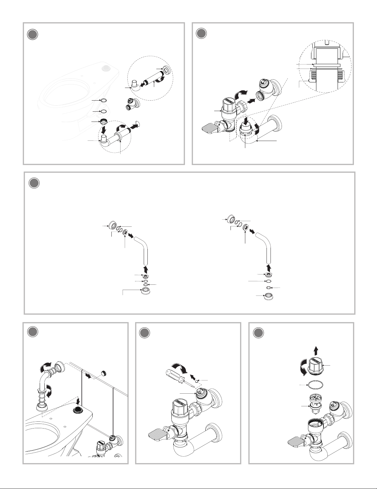
Verifique que el émbolo sea el correcto. (Pag. 2, paso 3). /
Verify that the piston is correct. (Page 2, step 3).
Abra totalmente la llave de retención. (Pag. 4, paso 18). /
Open fully the stop valve. (Page 4, step 18).
La descarga es poca o nula.
/ The discharge is low or null.
La presión de operación no es la adecuada. /
The operating pressure is not adequate.
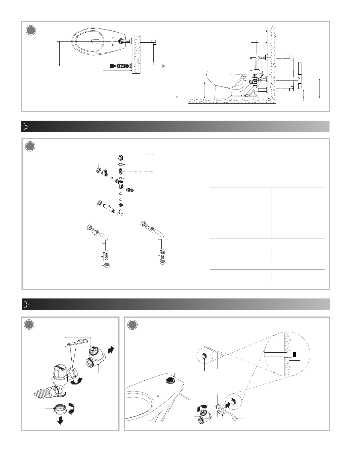
Verifique que la presión mínima de operación sea la correcta (Pag. 1). /
Verify that the minimum operating preasure is correct (Page 1).
La llave de retención está cerrada. /
The stop valve is closed.
Abra la llave de retención. (Pag. 4, paso 18). /
Open the stop valve. (Page 4, step 18).
La línea está obstruida. /
The supply line is obstructed.
Verifique que haya un buen flujo de agua retirando el émbolo y
purgando. (Pag. 4, pasos 10 al 19). / Check for good water
flow removing the piston and purging. (Page 4, steps 10 to 19).
El diámetro de la tubería no es la adecuada. /
The diameter of the pipe is not adequate.
Verifique que la tubería sea la indicada. (Pag. 1, dimensiones
recomendadas). / Check that the pipe are as stated. (Page 1,
recommended dimensions).
Las conexiones no están apretadas. /
The connections are not tight.
Apriete firmemente. /
Tighten firmly.
Las rondanas están torcidas o mal colocadas. /
The washers are bent or misplaced.
Verifique que las rondanas estén colocadas correctamente.
(Pag. 3, paso 8). / Verify that the washers are positioned
correctly (Page 3, steps 8).
Hay fuga en las
conexiones. / There are
leaks in the connections.
Acumulación de basura en la esprea del émbolo. /
Debris in the piston orifice.
Realice el mantenimiento del émbolo. (Pag. 5, paso 22 y 23). /
Do piston maintenance (Page 5, step 22 and 23).
No cierra el flujo o tarda
en cerrrar. / It shuts off the
flow or take to close.
Recomendaciones de Limpieza / Cleaning Recommendations
In Guadalajara:
Contact:
Enter our free
training courses.
In Monterrey:
En la Ciudad de México:
In Mexico City:
En Monterrey: En Guadalajara:
(52) 55 53 33 94 00
Ext. 5806, 5805 y 5804
33 36 19 01 13
Comunícate:
Participa en nuestros
cursos gratuitos
de capacitación.
81 83 33 57 67
81 83 33 61 78
HELVEX, S. A. DE C. V. Calzada Coltongo # 293, Col. Industrial Vallejo, Alcaldía Azcapotzalco, C. P. 02300, Ciudad de México.
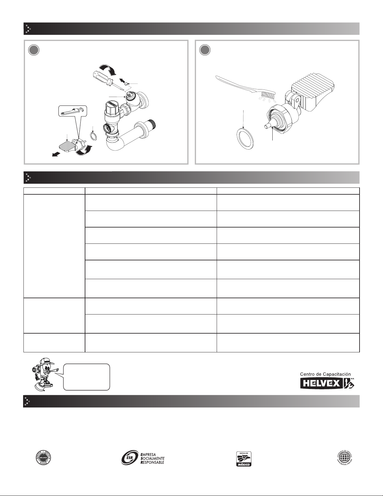
Mantenimiento del Pedal / Pedal Maintenance
Retire el tapón, cierre la llave de retención, realice la descarga de
agua y desenrosque el pedal. / Remove the stop valve cover,
close the stop valve, perform the discharge and unscrew the
pedal.
24 Verifique que el empaque cónico y la rondana no estén
desgastados, límpielos o cambielos si es necesario. / Check that
the tapered gasket and washer are not worn, clean or replace if
necessary.
25
empaque
cónico
tapered gasket
rondana
washer
rondana
washer
pedal
pedal
llave de retención
stop valve
It is very important to follow the instructions below to preserve HELVEX products
finishings, shiny and in perfect conditions:
1. Use only water and a clean cloth.
2. Do not use fibers, powders, abrasives, or chemicals.
3. Do not use sharp objects to clean the finishings.
4. It is recommended to clean your device daily
Visit our websites www.helvex.com.mx for México and www.helvex.com
for the international market
Es muy importante seguir las siguientes instrucciones para conservar los
acabados de los productos HELVEX, con brillo y en perfecto estado:
1. Utilice únicamente agua y un paño limpio.
2. No utilice fibras, polvos, abrasivos, ni productos químicos.
3. No utilice objetos punzo-cortantes para limpiar los acabados.
4. Se recomienda realizar la limpieza de su producto diariamente.
Visite nuestras páginas www.helvex.com.mx para México y www.helvex.com
para el mercado internacional
tapón
stop valve
cover

This manual suits for next models

3

Other Helvex Plumbing Product manuals

Helvex Maxima E-712 User manual

Helvex

Helvex Maxima E-712 User manual

Helvex 24-CH User manual

Helvex

Helvex 24-CH User manual

Helvex 5424 User manual

Helvex

Helvex 5424 User manual

Helvex SQUADRA E-710 User manual

Helvex

Helvex SQUADRA E-710 User manual

Helvex Vertika MP-1000 User manual

Helvex

Helvex Vertika MP-1000 User manual

Helvex Kúbica 14104 User manual

Helvex

Helvex Kúbica 14104 User manual

Helvex EP-94 User manual

Helvex

Helvex EP-94 User manual

Helvex UTR-035 User manual

Helvex

Helvex UTR-035 User manual

Helvex TH-058 User manual

Helvex

Helvex TH-058 User manual

Helvex RM-24 2-08-0902-5050 RM-26 2-08-0904-5050 User manual

Helvex

Helvex RM-24 2-08-0902-5050 RM-26 2-08-0904-5050 User manual

Helvex ARGOS UTV-296 User manual

Helvex

Helvex ARGOS UTV-296 User manual

Helvex H-3301-C/G User manual

Helvex

Helvex H-3301-C/G User manual

Helvex MAGNA DX UE-915 User manual

Helvex

Helvex MAGNA DX UE-915 User manual

Helvex FC-185-19 User manual

Helvex

Helvex FC-185-19 User manual

Helvex URM-22 User manual

Helvex

Helvex URM-22 User manual

Helvex Nuva E-3003 User manual

Helvex

Helvex Nuva E-3003 User manual

Helvex Explora HOT-106 User manual

Helvex

Helvex Explora HOT-106 User manual

Helvex TH-063 User manual

Helvex

Helvex TH-063 User manual

Helvex Clasica 104 User manual

Helvex

Helvex Clasica 104 User manual

Helvex SQUADRA E-711 User manual

Helvex

Helvex SQUADRA E-711 User manual

Helvex Argos TV-296 User manual

Helvex

Helvex Argos TV-296 User manual

Helvex Elite E-300-DX User manual

Helvex

Helvex Elite E-300-DX User manual

Helvex E-306 User manual

Helvex

Helvex E-306 User manual

Helvex Deco UDC-05 User manual

Helvex

Helvex Deco UDC-05 User manual

Popular Plumbing Product manuals by other brands

Moen BANBURY 82910CBN Illustrated parts list

Moen

Moen BANBURY 82910CBN Illustrated parts list

Dietsche Bravat P7231 N-RUS quick start guide

Dietsche

Dietsche Bravat P7231 N-RUS quick start guide

American Standard CCASF411-100 manual

American Standard

American Standard CCASF411-100 manual

leisurecraft Cedar Barrel Sauna with Half Moon Windows Assembly instructions

leisurecraft

leisurecraft Cedar Barrel Sauna with Half Moon Windows Assembly instructions

Dietsche BRAVAT P7305 Series Products Installation Instructions

Dietsche

Dietsche BRAVAT P7305 Series Products Installation Instructions

KEUCO Edition 90 59016 010200 Mounting instruction

KEUCO

KEUCO Edition 90 59016 010200 Mounting instruction

aquabrass Baguette 7145N installation guide

aquabrass

aquabrass Baguette 7145N installation guide

Hans Grohe AXOR Terrano 37405 Series manual

Hans Grohe

Hans Grohe AXOR Terrano 37405 Series manual

Hans Grohe PuraVida 15473 Series quick start guide

Hans Grohe

Hans Grohe PuraVida 15473 Series quick start guide

agape MEMORY MIX .EMIX441 Assembly instructions

agape

agape MEMORY MIX .EMIX441 Assembly instructions

Glacier bay HD67688W-6001 Installation and care guide

Glacier bay

Glacier bay HD67688W-6001 Installation and care guide

Hans Grohe AXOR Citterio Series Instructions for use/assembly instructions

Hans Grohe

Hans Grohe AXOR Citterio Series Instructions for use/assembly instructions

Price Pfister Avalon S104-3 installation instructions

Price Pfister

Price Pfister Avalon S104-3 installation instructions

BELLOSTA Jeans 4800/1/P Installation instruction

BELLOSTA

BELLOSTA Jeans 4800/1/P Installation instruction

American Standard Colony Soft 4275.500 installation instructions

American Standard

American Standard Colony Soft 4275.500 installation instructions

Dornbracht Touchfree operating manual

Dornbracht

Dornbracht Touchfree operating manual

Hans Grohe Axor Citterio 39400 Series Assembly instructions

Hans Grohe

Hans Grohe Axor Citterio 39400 Series Assembly instructions

Artos Trova FS309 installation guide

Artos

Artos Trova FS309 installation guide

manuals.online logo
manuals.online logoBrands
  • About & Mission
  • Contact us
  • Privacy Policy
  • Terms and Conditions

Copyright 2025 Manuals.Online. All Rights Reserved.