Dyson DC15 User manual

Issued 05/05
service manual

service manual
Issued 05/05
Self-adjusting stabiliser
Rear wheels lock in place when
the machine is upright, and tuck
neatly out of the way when the
machine is in use.
Motor location
Patented by Dyson, the motor is suspended
inside the ball feature, keeping the centre of
gravity low and improving manoeuvrability.
Cleanerhead geometry
The central pivot on the cleanerhead
ensures the head maintains perfect
contact with the floor even when the
machine is turning.
Motorised brushbar
Turn brushabr off at the touch of
a button to protect delicate rugs
or hard floors.
tteelleessccooppeerreeaacchh
Quick release wand expands for
instant cleaning. No awkward
parts to assemble for high-reach
cleaning.
Multi Cyclone technology
Advanced Dyson cyclone
technology.
Twists and turns like no other vacuum
the ball
DC15 key technology;

service manual
Issued 05/05
Introduction
Variants
Specifications
Electrostatic discharge
Electrical testing
Electrical circuit & resistance values
Electrical fault diagnostic
Product overview
Technical information
General notes
Removing the cleanerhead and yoke assembly
Removing and dismantling the yoke assembly
Dismantling the cleanerhead
Assembling the cleanerhead
Assembling and refitting the yoke assembly
Refitting the cleanerhead
Removing the ball and motor bucket
Dismantling the motor bucket
Assembling the motor bucket
Refitting the motor bucket and ball
Removing and dismantling the axlestand
Removing the stabiliser
Refitting the stabiliser
Assembling and refitting the axlestand
Removing and dismantling the valve cuff and valve seal
Assembling and refitting the valve cuff and valve seal
Removing and dismantling the valve assembly
Assembling and refitting the valve assembly
Removing the powercord assembly and switches
Refitting the powercord assembly and switches
Removing and refitting the internal cable
Removing and refitting the PCB to yoke loom
Dismantling the duct assembly
Hose/u-bend and wand assemblies
Cyclone and bin assemblies
Assembling the duct assembly
Fitting notes
Cleanerhead and yoke assembly
Duct, valve and stabiliser
Motor bucket and ball
Cyclone, bin, wand and hose/u-bend assemblies
Parts
6
8
9
2
1
1
2
PAGE
13
24
20
19
17
30
29
28
27
26
35
34
33
32
31
37
36
42
42
41
45
3
48
47
46
39
38
22
4
5
6

1
service manual
Issued 05/05
Product overview
Introduction
This manual is written specifically for Dyson trained engineers and covers the DC15 range. The service
instructions assume the engineer has the approved tools and test equipment with them.
Variants
DC15 overview
DC15 is the new unique upright from Dyson, with a whole range of features designed to make
vacuuming more efficient and less of a chore. The ball is what makes DC15 unique. By replacing
conventional wheels with a single ball, it enables the machine to manoeuvre around furniture and
obstacles with just a small turn of the wrist. The central pivot on the cleanerhead ensures that the
head maintains constant contact with the floor. To give great pick up and manoeuvrability, there is a
separate motor in the cleanerhead that powers the brushbar; this can be turned off at the touch of a
button for delicate rugs or hard floors. All DC15 products incorporate a quick-release wand, which
expands for instant cleaning and has no awkward parts to assemble.
allergy
HEPA plus Root8CycloneTM for cleaner expelled air
Low reach floor tool - cleans under low beds and sofas

service manual
Issued 05/05 2
Product overview
Specifications
With the advancement of technology within Dyson products, more sensitive electronic components
are being used. Certain variants of Dyson products (iinncclluuddiinnggDDCC1155) contain Printed Circuit
Boards (PCBs) which are made from electronic components that are susceptible to damage by
electrostatic discharge.
Electrostatic Discharge or ESD is described as the rapid transfer of electricity from one object to
another. Static electrical charge is created by the contact and separation of different materials e.g.
the motion of walking can create static electricity, as shoes contact and then separate from the floor.
Static electricity is released when two charged objects make contact and this is when sensitive
electrical components can be irreversibly harmed.
The damage caused by ESD varies from a product not functioning to a depreciation of the life of a
product; therefore it isn’t always possible to detect ESD damage.
In order to protect relevant Dyson product and components/assemblies from ESD damage, the
following precautions must be taken when repairing or examining product:
Using a socket polarity tester, verify that there is an adequate earth. If there is not an adequate
earth, use an alternative adequately earthed socket.
All repair/investigation work must be carried out on an anti-static mat that is earthed via an earthing
plug.
All personnel repairing/investigating Dyson product must wear an anti-static wrist strap that is
connected to an earthed anti-static mat (see Fig.1, page 3).
Electrostatic discharge
Technical info
DC15
allergy
Root8CycloneTM
Airwatts (constant)
Pre-filter
80W
1200W
2.5 litres
1120mm
347mm
384mm
8.65kg
11.99m
7.7m
200AW
HEPA
Lifetime
Post-filter
Mini turbine head
Debris slot
Brush control
Telescope reach wand
Bin capacity
Main motor
Brushbar motor
Cable length
Maximum reach
Height
Width
Depth
Operational weight
Low reach floor tool

service manual
Issued 05/05
3
ESD sensitive Dyson components/assemblies must also be handled and stored
appropriately. All ESD sensitive components will be labelled with the following logo:
It is important these components are taken out of the packaging only when needed and when suitable
earthed ESD protection is being worn/used. Should a component/assembly need to be placed down
during machine repair/investigation it is vital that it is placed on the earthed anti-static mat.
Earthed
workstation
Electrical testing
General safety note
All operating instructions contained within this service manual are intended solely for the use of
adequately trained personnel. The instructions assume the service engineer has the correct tools and
test equipment to complete the activity. Prior to using any consumer mains supply sockets you must
ensure the socket is tested for correct polarity.
Testing DC15 for correct insulation
The following insulation tests MUST be carried out prior to and on completion of all services to
DC15, and BEFORE any functional checks. You must ensure that a full visual inspection of the
product is completed prior to any service activity.
Ensure at all times during service and testing that consumers, pets and children
are not exposed to any live electrical supply.
Insulation test points
Test results
An insulation test reading of between 2 MΩand infinity is acceptable.
A reading of below 2 MΩis not considered safe and further investigation, rectification and testing
must be completed before the product is used.
Fig.1
Technical info

LIVE
NEUTRAL
8
7
6
9
D
10
11
12
13
15
14
16
5
2
3
14
A
B
C
4
service manual
Issued 05/05
Electrical circuit
Electrical resistance values
Technical info

service manual
Issued 05/05
5
Technical info.
Electrical fault diagnostic
1) When DC15 is switched on in the upright position, the brushbar motor is off. Tilting the machine into normal
vacuuming mode will automatically operate the upright switch, turning the brushbar motor on. The brushbar motor
can be switched off using the brushbar switch.
2) The vacuum motor of DC15 is fitted with a heat sensitive Thermal Cut-Out (TCO). This will shut the motor down for
up to 60 minutes if it reaches a temperature >96 degrees celcius. Excessive temperatures within the motor are
usually caused by machine / filter blockages.
3) The brushbar motor of DC15 is fitted with a current sensing protection circuit that will shut the brushbar motor off if
it is put under an excessive load (blocked / seized brushbar etc.). The protection circuit will remain off until it is reset.
This is achieved by: (a) pressing the brushbar switch.
(b) pressing the on / off switch.
(c) standing the machine upright and then re-tilting the machine into normal vacuum mode.
If the cause of the brushbar motor cut-out is not rectified the protection circuit will repeatedly reactivate, preventing the
brushbar from turning.
4) The fuse on the PCB assy is fitted for safety purposes. If the PCB fails, and the brushbar motor seizes, the fuse will
blow, cutting power to the brushbar motor.
Electrical fault diaignosis
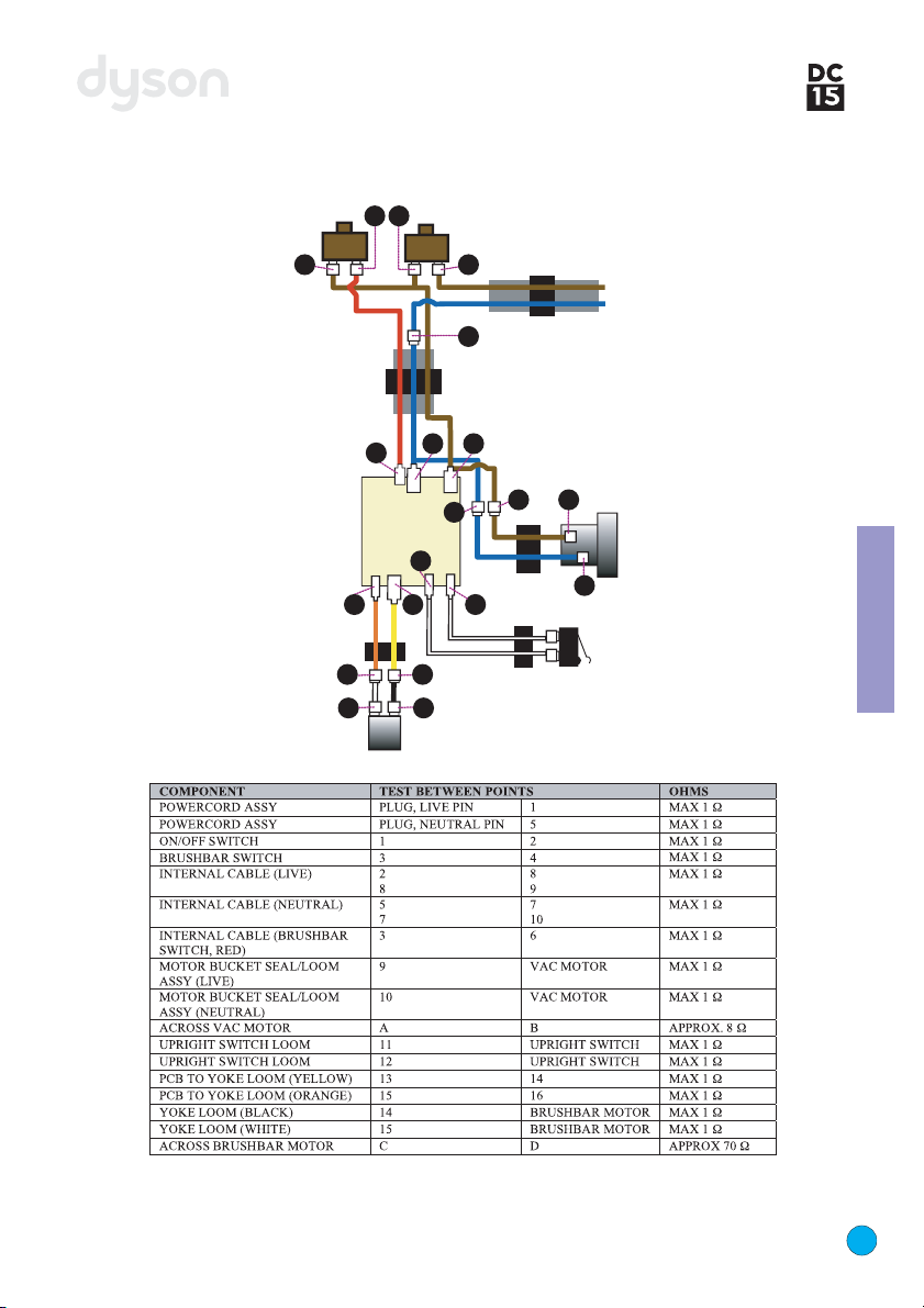
Note: all ‘connection’ numbers and ‘continuity’ checks refer to the illustrations on page 4.
NNoommaacchhiinneeppoowweerr((vvaaccmmoottoorraannddbbrruusshhbbaarrmmoottoorrooffff))..
1) Check for damage / electrical failure to the plug / fuse / powercord / connections to on / off switch and the
mechanical switch actuation.
2) Check for a loose connection at points 11,22aanndd55..
3) Check continuity of powercord on / off switch / and internal cable.
NNooppoowweerrttootthheevvaaccmmoottoorr((bbrruusshhbbaarrmmoottoorroonniinnttiillttppoossiittiioonn))..
1) Check connections at points 99,,1100,,AAand BB.
2) Check continuity of internal cable and motor bucket seal/loom assembly.
3) Check vac motor continuity and motor brushes, windings, commutator etc.
NNooppoowweerrttootthheebbrruusshhbbaarrmmoottoorr((mmoottoorrvvaaccoonn))..
1) Check connections at points 77,,88,,1133,,1144,,1155,,1166,,CCaannddDD.
2) Check the continuity of the internal cable, PCB to yoke loom and the yoke loom assembly.
3) Check brushbar motor continuity and motor brushes, windings, commutator etc.
If all of the checks listed are correct the PCB will be at fault.
BBrruusshhbbaarrmmoottoorroonniinnuupprriigghhttppoossiittiioonn((sswwiittcchheessooffffwwiitthhbbrruusshhbbaarrsswwiittcch
h))..
1) Check connections at points 1111and 1122.
2) Check continuity of upright switch and upright switch loom.
3) Check the actuation of the of the upright switch.
If all of the checks listed are correct the PCB will be at fault.
BBrruusshhbbaarrsswwiittcchhddooeessnnoottsswwiittcchhbbrruusshhbbaarrmmoottoorrooffffiinnttiillttppoossiittiioonn..
1) Check connection to brushbar switch at points 33,,44and point 66.
If all of the checks listed are correct the PCB will be at fault.
BBrruusshhbbaarrmmoottoorroonnppeerrmmaanneennttllyy((wwiillllnnoottsswwiittcchhooffff))..
1) Check for a short in the upright switch loom.

service manual
Issued 05/05
Fitting notes
Before attempting any repairs it is vital to ensure that the product is
totally isolated from the mains supply and that accidental
reconnection cannot occur.
Removing the cleanerhead and yoke assembly
General notes
6
Undo the two screws to the side of the yoke.
Slide the yoke cover away from the side of
the yoke to expose the connections.
1
2
Where this symbol is shown ensure ESD protection is used.
All screws used in DC15 are Torx T15, unless otherwise stated.
Assembly guide
The fitting notes contained within this service manual are separated into the following assembly
sections:
Cleanerhead and
yoke
Ball and motor
bucket
Cyclone and bin
Duct
Wand handle and
hose
Stabiliser and
axlestand
Valve

service manual
Issued 05/05
7
Fitting notes
Remove the yoke spigot from the side of
the product.
Pull the cleanerhead hose off the underside
of the valve assembly.
Drop the cleanerhead as far forward as
possible.
Pull the cleanerhead away from the front of
the product.
5
6
7
8
Turn the product around and undo the
screw in the yoke spigot.
4
Carefully disconnect the yoke loom from
the PCB to yoke loom.
3

service manual
Issued 05/05 8
Fitting notes
Removing and dismantling the yoke assembly
Release the yoke loom from the back of the
yoke assembly.
Remove both gimble clips from either side
of the cleanerhead top hinge.
Prise the large and small gimble clips out of
either side of the cleanerhead top hinge using a
thin flat bladed screwdriver.
Push the end of the gimble lock arm
assembly out of the same side of the yoke.
Prise the rear of the hose guard out of the
yoke using a thin flat bladed screwdriver.
Remove the yoke assembly from the rear
of the cleanerhead top hinge.
9
10
11 14
13
12

service manual
Issued 05/05
9
Fitting notes
Prise the other end of the gimble lock arm
assembly out of the yoke using a thin flat
bladed screwdriver, ensuring that you retain the
gimble lock arm spring.
Carefully remove the actuator arm spring
from the gimble lock arm using a thin flat
bladed screwdriver.
Dismantling the cleanerhead
Undo the two fasteners on the rear of the
end cap assemblies.
Untwist both end cap assemblies and pull
from the side of the brush housing.
Pull both halves of the brushbar assembly
out of the brush housing.
15
16
19
18
17
gimble lock arm spring

service manual
Issued 05/05 10
Fitting notes
Undo the screw in the underside of the brush
housing.
Undo the four black screws in the top of the
brushbar motor cover.
Remove the brushbar motor cover assembly
off the top of the brush housing.
Lift out the two brushbar motor top mounts
from inside the brushbar motor cover assembly.
Remove the cleanerhead spring from the
top of the brush housing.
23
24
22
21
20
Carefully unclip the yoke loom wires from
the end of the brushbar motor assembly.
25

service manual
Issued 05/05
Undo the five Pozi screws in the soleplate.
Note that the central screw is shorter than the
other four.
31
11
Fitting notes
Lift the yoke loom off the top of the brushbar
motor.
Lift the brushbar motor assembly out of the
brush housing.
Remove the brushbar motor end mount
from the end of the brushbar motor assembly.
Firmly pull the cleanerhead hose off the rear
of the brush housing.
Carefully remove the brushbar motor bottom
mount from inside the brush housing.
28
29
30
27
26

service manual
Issued 05/05 12
Fitting notes
Lift the front edge of the soleplate off the
brush housing. Then unclip from the rear.
Lift the glamour cover out of the rear of
the brush housing.
Slide out the brushbar motor front mount
from the front of the brush housing.
Lift the four soleplate wheels and axles out
of the underside of the brush housing. Slide the
wheels off the axles.
Release both bumper catches from the
front of the brush housing using a Torx
screwdriver.
34
35
36
33
32
Firmly push the bumper and bumper
rubber off the front of the brush housing.
37

service manual
Issued 05/05
13
Fitting notes
Assembling the cleanerhead
Carefully peel the bumper rubber out of
the bumper.
Lower the bumper rubber into the location
slots at the front of the brush housing.
Align the screw bosses on the bumper with
the holes on the brush housing. Firmly press
until the catches clip into position.
Refit the brushbar motor front mount into the
brush housing.
38
41
40
39

service manual
Issued 05/05 14
Fitting notes
Lower the glamour cover into the brush
housing.
Slide the soleplate wheels onto the axles.
Fit both parts into the brush housing.
Clip the rear edge of the soleplate into the
brush housing and then lower the soleplate onto
the brush housing. Refit the five Pozi screws
ensuring that the short screw locates in the
centre.
Lower the brushbar motor assembly into
the brush housing.
Refit the brushbar motor end mount onto
the end of the brushbar motor assembly.
Refit the brushbar motor bottom mount
into the brush housing.
45
46
47
44
43
42

service manual
Issued 05/05
Refit the cleanerhead spring onto the cruciform
on the brush housing. Lower the brushbar motor
cover assembly over the yoke loom.
53
15
Fitting notes
Turn the brush housing over and locate the
motor into the brushbar motor front mount. Push the yoke loom grommet into the locator
in the brush housing. Locate the grommet onto
the brushbar motor assembly. Press the sheaving
into the channel on the brush housing.
Lower the brushbar motor assembly onto
the brushbar motor bottom mounts. Attach
both yoke loom wires onto the end of the
brushbar motor.
Refit both brushbar motor top mounts into
the brushbar motor cover assembly.
Locate the end of the outer insulation
sheathing behind the wall as shown.
48
49
50
52
51

service manual
Issued 05/05 16
Fitting notes
Align the cleanerhead spring with the
cruciform on the base of the brushbar motor
cover assembly. Push the endcap assemblies onto the ends
of each brushbar and twist into place. Then
retighten the endcap fasteners.
Align the end of each half of the brushbar
assembly with the brushbar motor spindle. Push
each half of the brushbar assembly onto the
spindle.
Refit the cleanerhead hose onto the brush
housing.
56
57
58
54
Lower the brushbar motor cover assembly
onto the brush housing. Hold in place whilst
refitting the four black screws in the top of the
brush housing and the screw in the underside.
55

service manual
Issued 05/05
Slide the hose guard into the channels on
the side of the yoke until the release catch clips
into position.
64
17
Fitting notes
Assembling and refitting the yoke assembly
Place the actuator arm spring onto the
actuator arm. Using a thin flat bladed
screwdriver, position the other end of the spring
between the two retainers inside the gimble lock
arm.
Lower the gimble lock arm spring into the
gimble lock arm assembly.
Clip the other end of the gimble lock arm
assembly into the side of the yoke.
Carefully press the gimble lock arm spring
and the actuator arm into the yoke. Press the
gimble lock arm assembly onto the yoke.
Position the hole on the side of the gimble
lock arm assembly onto the yoke.
61
62
63
60
59
Other manuals for DC15
5
Table of contents
Other Dyson Vacuum Cleaner manuals

Dyson
Dyson v6 SV03 User manual

Dyson
Dyson DC24 Blueprint Limited Edition User manual

Dyson
Dyson Dc45 User manual

Dyson
Dyson 368339-01 User manual

Dyson
Dyson V6 Absolute User manual

Dyson
Dyson V6 Absolute User manual

Dyson
Dyson DC21 Motorhead User manual

Dyson
Dyson DC22 User manual

Dyson
Dyson Slim User manual

Dyson
Dyson V6 Absolute User manual

Dyson
Dyson DC11 Telescope User manual

Dyson
Dyson BIG BALL User manual

Dyson
Dyson Ball Animal User manual

Dyson
Dyson DC26 User manual

Dyson
Dyson DC34 ANIMAL User manual

Dyson
Dyson Big Ball Series User manual

Dyson
Dyson V6 Absolute User manual

Dyson
Dyson 1989405 User manual

Dyson
Dyson DC40 User manual

Dyson
Dyson SV03 User manual