DZ SIENNA User manual

Page
DZKit
USER’S MANUAL
SIENNA
SIENNASIENNA
SIENNA
HF RECEIVER/Transceiver
HF RECEIVER/TransceiverHF RECEIVER/Transceiver
HF RECEIVER/Transceiver
Price: 20.00
DZ CompanY • LOVELAND, COLORADO

Page 2
DZ COMPANY CONTACT INFO
Orders, parts, phone assistance.....................................................................(970) 667-2254
Email orders............................................................................................... sales@dzkit.com
Email technical support .........................................................................[email protected]
Web site.......................................................................................................www.dzkit.com
Mail:
DZKit
710 Grove Ct.
Loveland, CO 80537
During your first ninety (90) days of ownership, DZ Company will replace or repair free of charge—as soon as
practical—any parts which are defective, either in materials or workmanship You can obtain parts directly from
DZ Company by writing us, emailing us or telephoning us And we’ll pay shipping charges to get those parts to
you—anywhere in the world
We warrant that during the first ninety (90) days of ownership, our products, when correctly assembled,
calibrated, adjusted and used in accordance with our printed instructions, will meet published specifications
You will receive free consultation (except for the cost of your long distance phone call) on any problem you may
encounter in the assembly or use of your DZKit product Just drop us a line, email us, give us a call, or visit our
website and click on “Support” That will give you access to free on-line support and a discussion group Sorry,
we cannot accept collect calls
Our warranty, both expressed and implied, does not cover damage caused by the use of corrosive solder,
defective tools, incorrect assembly, misuse, fire, customer-made modifications, floods or acts of God, nor does it
include reimbursement for customer assembly or setup time The warranty covers only DZKit products and is
not extended to non-DZ allied equipment or components used in conjunction with our products or uses of our
products for purposes other than as advertised
If you are ever dissatisfied with our service—warranty or otherwise– or our products, please write or email the
president, Brian Wood, W0DZ, and he will make certain your problems receive prompt, personal attention
THE DZ COMPANY, LLC
LOVELAND, CO 80537
YOUR DZKIT 90-DAY FULLWARRANTY

Page 3
Operation
Of the
Sienna HF Receiver/Transceiver
DZ COMPANY
LOVELAND, COLORADO
Copyright © 2013
The DZ Company, LLC
All rights reserved
11/20/2014 ….…………………………………Sienna
TABLE OF CONTENTS
Introduction .......................................4
Back Panel.........................................6
Front Panel.........................................8
Basic Operation ...............................14
The Receiver....................................20
The Transmitter................................32
The Antenna Tuner ..........................40
External Amplifiers..........................42
The Menu.........................................43
Appendix A: APP Connectors .........58
Appendix B: External Keypad.........60
Appendix C: RS-232C Commands .62
Appendix D: Balanced Mic usage...89

Page 4
Your new Sienna HF Receiver/
Transceiver represents the perfect
integration of computers and ra-
dio. It’s not just a radio and
with its companion Sedona not
just a PC. In fact if you don’t
like PCs you don’t have to have
one!
Some “software-defined radi-
os” (SDR) require you to have a
PC either internal or external
because after converting the radio
spectrum into digital samples
that data is passed over a high
speed link to a PC for processing.
Sedona’s PC is totally optional
because we know that some of you
like PCs and some do not.
Sienna uses a triple conversion
receiver. By “up-converting” the
entire 0-54 MHz spectrum to 70
MHz it becomes possible to easily
filter out the mixing products
resulting in excellent image re-
jection. In addition there are no
dead spots in the shortwave bands
which is a necessary side effect
of down-conversion radios.
At 70MHz it is not currently pos-
sible to have narrow crystal fil-
ters) - they are just too expen-
sive. But Inrad manufactures an
excellent 6-pole crystal filter
for the Yaesu FT-1000MP that Sien-
na also uses. At 4.5kHz it is
still excellent for good AM copy
while providing much better block-
ing dynamic range than you would
get with a wider filter.
Sienna is also one of the only ra-
dios on the market with a com-
pletely separate transmitter and
receiver. There are no shared com-
ponents or oscillators. Thus full
-duplex operation such as that
used in satellite operation is
possible. Full duplex also allows
you to monitor your signal. A sep-
arate transmitter and receiver and
it also allows true cross-band/
cross-mode operation.
Introduction

Page 5
Modularity is another of Sienna’s
features. The chassis has six com-
partments — power receiver
transmitter 100W amp control and
auxiliary. This affords excellent
shielding and also provides easily
serviceable components. Should the
transmitter ever need service it
can be removed without disturbing
anything else.
Cooling in Sienna is also im-
portant. Two central fans pull air
in from the front sides cooling
the display and controller chips
passing it across the transmitter
amplifier and DC power distribu-
tion boards and exhausting it out
the back. Thermistors regulate the
fan speeds.
Finally a lot of attention has
been paid to ergonomics. Sienna’s
controls are grouped by function
and dual functionality is used
sparingly and carefully. The most
common controls are on the front
panel while the ones used less
often are in the first level menu
(which is always on the display—
AGC NB VOX/PTT Antenna selec-
tions). Other less often used
functions are in a very simple
menu system. An external 12-button
keypad is supported (and built-in
to Sedona) which allows easy ac-
cess to memories CW buffers and
one-button-per-band bandswitching.
Sedona’s internal PC adds all the
features of a PC (logging web
connectivity USB rig control
digital modes mic processing
etc.) that are often handled in
other rigs by the use of expensive
“rig interface” boxes. With Sedo-
na’s internal PC you don’t have
nearly the mess of external wires
that you would have with an exter-
nal PC making portable operations
much more convenient. And in a
matching case to Sienna!

Page 6
Back Panel
1. Keypad. Connect a 12-button keypad such as the Yaesu FH-2 to this
connector. See Appendix B for details on how to build your own.
This allows you to change bands with a single keypress use the
memory features and select a band directly instead of using band
up or down controls. This connects directly to Sedona or to a aesu
FH-1 or FH-2 keypad.
2. Key. The manual and paddle jacks are connected in parallel with
those on the front panel and are both active simultaneously so that
you do not have to turn the keyer off to use a straight key or ex-
ternal keying device.
3. Audio. Line-in and Line-out are stereo 600 ohm audio inputs and
outputs that can be connected to the sound card on a PC or other
audio devices. Line level is nominally 200mVrms.
4. 455KHz IF Out. This is a large bandwidth output centered at 455KHz
that can be connected to a spectrum analyzer or panadapter to view
signals on the current receive band.
5. RX Antenna. This BNC connector allows you to run the receiver from
an antenna that is not connected to the transmitter. It is protect-
ed from static by a gas discharge tube but not against high trans-
mitter power. Maximum input power is 1mW (0dBm).
6. ALC In (RED). This phono connector allows 0 to –5VDC input from an
external linear amplifier to control the output level of the inter-
nal 100W amp. Higher negative voltages produce lower output power.
7. PTT In ( REEN). This phono connector provides a push-to-talk input
that is wired in parallel with the PTT pin in the front panel mic
connector. Ground the input to enable the transmitter. It is pulled
up internally to 5V with a 1K resistor.
8. Mic In (BLUE). Unbalanced audio from this phono connector is mixed
with the front panel microphone connector or with the internal line
13 14 15 16 17
1 2 3 4 5 6 7 8 9 10 11 12

Page 7
signal from the Line In connector. The input impedance is about 10K
ohms.
9. Antenna A. This SO-239 connector is the main transmit/receive an-
tenna. It is protected from static discharge by a gas discharge
tube.
10.Antenna B. This SO-239 connector is a secondary antenna. A menu
item lets you select antenna A or B. It is protected from static
discharge by a gas discharge tube.
11. ND. This is chassis ground. Connect this to a good earth ground.
12.DC In. These Anderson Powerpole connectors are the main DC Input.
Connect these to a clean source of DC voltage from 11-15VDC. The
transmitter will operate from 12-15V. The receiver can operate over
the full range.
13.RS-232C I/O. Connect this serial port to a PC or to another Sien-
na.
14.Exhaust holes. These holes serve as exhaust for the internal fan.
Do not block these holes.
15.Linear. 8-pin mini-DIN connects to linear amplifier
16.Exhaust plate. This bracket provides exhaust for the fan that cools
the DC power distribution board and optional 100W amplifier. Do not
block the exhaust holes.
17.Fuse. This 25A fuse is inline between the main power input and the
optional 100W amplifier. If the amplifier is not installed this
opening can be replaced with a hole cover or used to bring cables
in and out if you wish to use the compartment to hold a battery or
other device.

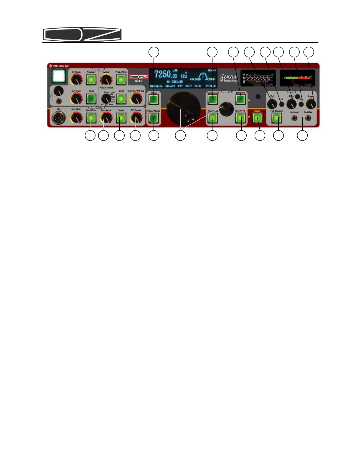
Page 8
Front Panel Controls
1. RF ain (RF or Radio Frequency ain). This control overrides the
automatic gain control (AGC) of the Receiver’s Intermediate Fre-
quency (IF) amplifiers. In its CW (clockwise) position the AGC has
full control over the gain. As you rotate the control counter
clockwise (CCW) it reduces the available gain. This control is
usually left in the CW position unless extremely strong signals are
present. It can also be used to reduce sensitivity so that only
stronger signals are heard which can help during contests.
2. Preamp1. This switch activates the first of two available RF ampli-
fiers. On lower frequencies below 10MHz this amplifier is often
not needed. Above 10MHz it is not needed when band conditions are
excellent. It is useful for pulling out very weak signals on a fad-
ing band.
3. Pre2/Atten. This switch activates the second of two available RF
amplifiers only if the Preamp1 switch (see previous item) is
pushed. If Preamp1 is off this button serves as a 10dB attenuator.
If you use the attenuator and then push the Preamp1 button the at-
tenuator is disengaged and both preamps are turned on. You should
only need both preamps to pull out very weak signals as this much
RF gain increases distortion on strong signals.
4. Headphone volume. This control adjusts the gain of the headphone
audio amplifier. It can be adjusted separately from speaker volume.
5. Headphone jack. Plug low impedance stereo headphones into this
3.5mm minijack connector.
6. AF ain (AF or Audio Frequency ain). This control adjusts the
gain of the speaker audio amplifier. Speaker volume can be adjusted
separately from the headphone volume.
7. Mute. This button mutes all sources both the internal receiver and
any audio from the line in jack.
8. Dual. This button activates dual receive. In this mode input from
12 13 8 9
4 5 6 1 2 7 10 11 3

Page 9
the stereo Line In jack on the back panel is fed to the speakers
and the internal receiver is fed only to the right speaker. This
allows you to listen to one receiver in each ear. In order to feed
a mono source such as a receiver to the left channel only you must
connect the left channel to the external receiver but not the
right. This can be done by using a mono minijack plug in the stereo
minijack.
9. FM Squelch/NB Thresh. In FM mode, this control sets the level at
which FM signals are quieted (squelched). In other modes this con-
trol sets the noise blanker threshold if the noise blanker is
turned on.
10.Adjust. This control consists of a rotary pulse generator (RPG) and
a pushbutton switch. The function of the RPG and the switch depend
on the 8-position switch immediately below it (11).
11.Multipurpose switch. This switch selects up to 8 different modes
for the RPG control that is above it (10). In the CCW position it
enables the RPG to change which IF filter is selected. Pushing the
RPG knob switches back and forth between the 9MHz and 455KHz fil-
ters and a * is placed next to the currently selected set in the
display. The width of the trapezoids in the display changes to give
a visual indication of the bandwidth of the selected filter. Note:
when you change bands or modes the previously saved filter is au-
tomatically selected. In position 2 the switch allows the 9MHz or
455KHz passband (whichever is selected) to be shifted right or left
50Hz per detent. Position 3 selects the notch filter when the ad-
just button is pushed. Position 4 is reserved for future use. Posi-
tion 5 allows the pushbutton to start or stop scanning functions.
Position 6 of the switch accesses the CW buffers (which are set in
menu options). The rotary control selects one of the ten buffers
and the pushbutton starts the buffer. Position 7 is for memory
buffers. Rotating the RPG selects a memory and the pushbutton then
moves it into VFO A. Position 8 is the “Birdcage” labeled “BC”. In
this position rotating the Adjust knob shifts the 1st IF left or
right by 50Hz per click. Pushing the button resets all IF shifts to
0. The birdcage is very useful for removing spurious receiver mix-
ing products (“birdies”) that are present in all superhet receiv-
ers.
12.Microphone jack. This connector is wired for a Yaesu compatible mi-
crophone. An external adapter is required for use with other micro-
phones.
13.Mic ain. This control adjusts the microphone gain. Use it with the
ALC meter indication on transmit to keep from overmodulating the
final amplifier.
Page 10
14.Proc/CW Spot. In SSB mode this button activates the RF speech pro-
cessor. In CW mode this button disables the transmitter and allows
the keyer (internal or external) to be used as a SPOT control. To
use this function press the key and turn the Pitch control (20)
until the sidetone frequency matches that of the received signal.
This assures that you are transmitting on the same frequency as the
station you wish to communicate with. CW SPOT mode can also be used
for code practice since no signal will emanate from the transmit-
ter. It is useful to press the Mute button in this mode too to
eliminate receiver noise. You do not need to change the RF Power
control when using CW SPOT.
15.Proc Level. This control adjusts the compression level. Use on SSB
with the Compression scale on the meter to keep speech compression
less than 10 dB.
16.Tuner. This button activates the optional internal Antenna Tuner.
The tuner memory saves up to 30 settings and allocates them into
32kHz of spectrum from 0 to 30MHz on a per-antenna basis (A or B
antenna). If a band segment on a particular antenna has never been
tuned then if this switch is on the first time you transmit on
that band segment a tuning operation will occur and the settings
will be memorized. When the switch is off the tuner is bypassed. A
menu option allows you to reset the tuner settings or force a tune
operation on a band segment that was alreadt tuned. In that menu
you can also see what the tuner selected and change the inductance
and capacitance manually.
17.RF Power. This control adjust the transmitter power level from 0 to
11.8W (118W if the 100W amp is present and enabled). Note that this
is “requested” power. Actual power is measured in real-time by the
ALC (Automatic Level Control) firmware and will be as close as pos-
sible to this value. If the “ALC Threshold” menu setting is “0”
the display reads “P-Rel” which means that the RF Power control is
a relative uncalibrated value.
18.Sidetone Volume. In CW mode this control adjusts the volume of the
14 15 16 17 26 32 27 30 31 23 24
25 28 29 18 19 20 21 22
Other manuals for SIENNA
3
Table of contents
Other DZ Transceiver manuals


