DZ SIENNA User manual

Page
DZKit
ASSEMBLY MANUAL
SIENNA
SIENNASIENNA
SIENNA
HF RECEIVER/Transceiver
HF RECEIVER/TransceiverHF RECEIVER/Transceiver
HF RECEIVER/Transceiver
Price $30.00
DZ CompanY • LOVELAND, COLORADO

Page 2
DZ COMPANY CONTACT INFO
Orders, parts, phone assistance.....................................................................(970) 667-2254
Email orders............................................................................................... sales@dzkit.com
Email technical support .........................................................................[email protected]
Web site.......................................................................................................www.dzkit.com
Mail:
DZKit
710 Grove Ct.
Loveland, CO 80537
During your first ninety (90) days of ownership, DZ Company will replace or repair free of charge—as soon as
practical—any parts which are defective, either in materials or workmanship You can obtain parts directly from
DZ Company by writing us, emailing us or telephoning us And we’ll pay shipping charges to get those parts to
you—anywhere in the world
We warrant that during the first ninety (90) days of ownership, our products, when correctly assembled,
calibrated, adjusted and used in accordance with our printed instructions, will meet published specifications
You will receive free consultation (except for the cost of your long distance phone call) on any problem you may
encounter in the assembly or use of your DZKit product Just drop us a line, email us, give us a call, or visit our
website and click on “Support” That will give you access to free on-line support and a discussion group Sorry,
we cannot accept collect calls
Our warranty, both expressed and implied, does not cover damage caused by the use of corrosive solder,
defective tools, incorrect assembly, misuse, fire, customer-made modifications, floods or acts of God, nor does it
include reimbursement for customer assembly or setup time The warranty covers only DZKit products and is
not extended to non-DZ allied equipment or components used in conjunction with our products or uses of our
products for purposes other than as advertised
If you are ever dissatisfied with our service—warranty or otherwise– or our products, please write or email the
president, Brian Wood, W0DZ, and he will make certain your problems receive prompt, personal attention
THE DZ COMPANY, LLC
LOVELAND, CO 80537
YOUR DZKIT 90-DAY FULLWARRANTY

Page 3
Assembly
Of the
Sienna HF Receiver/Transceiver
DZ COMPANY
LOVELAND, COLORADO
Copyright © 2014
The DZ Company, LLC
All rights reserved
11-20-2014 Sienna
TABLE OF CONTENTS
Introduction .......................................4
General assembly/safety notes ..........6
Step-By-Step Assembly
Chassis, DC power, Tuner..........14
Initial tests...................................34
Front Panel integration...............32
Front Panel tests..........................42
Receiver Integration ...................44
Receiver alignment/test ..............53
Transmitter integration ...............63
Transmitter resistance/voltage....65
Transmitter alignment/tests ........67
100W PA Integration ..................73
100W PA alignment/tests............76
Final assembly............................79
Appendix A: (Reserved)..................81
Appendix B: RS232 Board..............85
Appendix C1: DCD: Power ............87
Appendix C2: DCD: SWR .............95
Appendix C3: DCD: Tuner..............97
Appendix C4: 5V Regulator..........101
Appendix D1: Blank Front Panel..103
Appendix D2: Full Front Panel .....105
Appendix E: IF Filter Board..........109
Appendix F: RXBPF Board...........115
Appendix G: Receiver Board ........120
Appendix H: Transmitter Board....129
Appendix I: 100W PA Board.........141
Appendix J: Installing Filters........152
Appendix K: IF Test Procedure.....156
Appendix L: RXBPF Test Proc.....158

Page 4
The Sienna family of receivers/
transceivers represents a revolu-
tion in amateur radio. Now you
can start with a relatively inex-
pensive remote-control-only re-
ceiver, using a PC to control it
using your favorite software, and
then add a front panel, transmit-
ter, tuner and amplifier, as well
as numerous F filters, as your
desires or budget allow. Or you
can start with any combination of
modules to create just the right
radio for your needs.
The time-tested triple-conversion
receiver design assures general
coverage receive with no dead
spots and excellent image rejec-
tion. t also has very good dy-
namic range by virtue of a 5KHz
roofing filter at the 70.455MHz
first F, and compatibility with
a wide variety of high perfor-
mance crystal filters and Collins
mechanical filters at the 2nd and
third F’s to provide excellent
selectivity. We’ve also added in-
novations in AGC control, band-
pass filtering with GaAsFET
switches instead of P N diodes,
and the ability to run full-
duplex and cross-band at HF fre-
quencies.
Sienna transceivers are also a
study in duality: dual preamps,
dual keying (manual and paddle
inputs available at the same time
on both the front and back pan-
el), dual audio (headphones and
speakers available at the same
time), dual receive (front panel
access to the audio from an ex-
ternal secondary receiver), and
dual backlit analog meters, which
give the rig a nice glow that
harkens back to the early days of
radio when all radios glowed. Du-
al microprocessors are in total
control of the radio.
The Sienna can be built in sever-
al stages and in several combina-
tions. This manual is thus a com-
plete assembly manual for the
fully loaded Sienna. As you up-
grade your Sienna, you can still
use this one manual as a complete
assembly reference.
Thanks for trusting in DZKit to
provide not only unique electron-
ic products, but to give you
hours of building fun too.
INTRODUCTION

Page 5

Page 6
1. Most screws in this kit are
Phillips Panhead Machine
Screws. For simplicity, we
refer to them simply as
“screws” unless a different
style is used. These may be
stainless steel or zinc-
plated steel.
2. Almost all sheet metal parts
are attached to each other
using 6-32 x 1/4” screws that
are inserted into captive
fasteners that have been
pressed into the sheet metal.
These screws have a locking
compound on them to keep them
from vibrating loose.
3. Most PC boards attach to the
sheet metal using 6-32 x 1/4"
screws with attached lock-
washers (“SEMS” screws) but
there are some exceptions,
which are explained in the
steps.
4. As you tighten a screw, it is
very important that you do
not strip the threads. All
screws should fasten smooth-
ly. f a screw appears to be
very hard to fasten, some-
thing else is probably wrong—
a cable could be in the way,
you are trying to use the
wrong size screw or something
else is wrong. DO NOT FORCE
SCREWS! nstead, inspect the
assembly carefully and try to
see why you are having diffi-
culty. Screws with locking
compound on them are normally
a little harder to fasten.
5. A PC within arms reach of
your workbench is useful in
helping you locate the parts
on the boards. Shipped with
your kit is a USB flash drive
containing the PCB layout
files for all boards (without
traces). To find the location
of a part, simply install and
run the “ExpressPCB” program
(free download from
www.expresspcb.com) and open
the board you wish to work
on. Press “Ctrl-F” to find a
part, and then enter it in
the box that pops up (e.g.,
“R1”, without the quotes).
The program will show you ex-
actly where that part is lo-
cated. Take a few minutes to
familiarize yourself with
this program before beginning
construction. You can also
find parts manually by just
looking for the part on the
silkscreen, but on the denser
boards, this can take a long
time. We highly recommend us-
ing ExpressPCB to locate
parts.
6. There are three large sheet
metal brackets. Two are iden-
tical and are placed opposite
each other lengthwise from
front to back. These brackets
are referred to as "large
bracket LR" (for Left/Right).
The other large bracket runs
from side to side in the
front, attaching to the other
brackets. t is called the
General Assembly Notes

Page 7
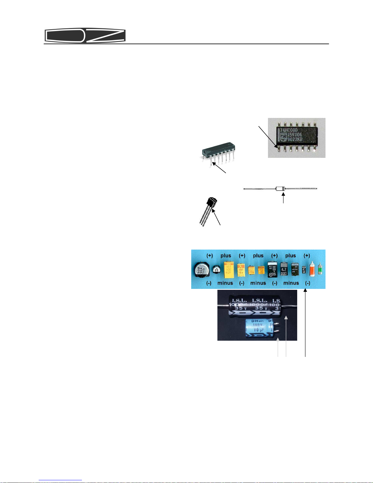
Most kit builders find it helpful to sepa-
rate the parts into categories for quick
identification. Muffin tins and egg car-
tons serve this purpose admirably.
"front bracket".
7. All references to left and
right, front and back are with
the chassis in an orientation
such that the front of the ra-
dio faces you. The large open-
ings on the bottom of the
chassis are to the right, with
the folded sides pointed up.
8. Each circuit part has its own
component number (R1, L4, Q3,
etc.). R1 on one assembly will
not be the same as R1 on a
different assembly, so be sure
you are looking at the right
set of parts when comparing
part numbers with the printed
parts list. Check off each
part at the beginning of each
section to make sure all the
parts are there. f you find
any missing, give us a call or
email us and we will rush a
replacement to you.
9. Most electronic kits that are
returned for service have poor
soldering jobs. Please take a
moment to familiarize yourself
with proper soldering tech-
nique. And do not, under ANY
circumstances, use corrosive
(“acid-core”) solder! That
will void your warranty and
render your kit inoperative.
Also be sure to avoid the use
of products that may be called
solder but are really glue
(e.g., LePage's Liquid Solder,
nothing more than metallic-
grey colored airplane glue).
10.Soldering should only be done
in an area with good ventila-
tion and with a properly heat-
ed soldering iron.
11.Resistors are identified by
their values in Ohms, Kilohms
(K) or Megohms (M) and by col-
or codes. Your kit uses resis-
tors of several types. Axial
leaded resistors have color
coded bands on them. For 5%
resistors, the first two bands
represent the numeric value
and the third band represents
a multiplier, which is a power
of 10. Thus, a 56 Ohm resistor
is Green-Blue-Black. A 10KOhm
resistor is Brown-Black-
Orange, and so on. The fourth
band is the tolerance — no
band represents 20%, a silver
band 10%, and a gold band 5%.
Your Sienna uses mostly one
percent or better resistors,
which have 4 bands for the
value. A 4.75K resistor is
Yellow-Violet-Green-Brown. We
have placed resistors of given
types in individual bags for
you, but should they get mixed
and you have trouble reading
the color code, we recommend
an inexpensive volt-ohmmeter
be used to check the values. A
fluorescent light is also use-
ful to “bring out” the colors,

Page 8
and a magnifying glass is also
handy.
12.Capacitors are identified by
their type — disk, polysty-
rene, polypropylene, electro-
lytic, trimmer, etc.) and ca-
pacitance values are in micro-
farads (uF) or picoFarads
(pF). Polarized types have the
positive pin marked on the
silkscreen and also have a
square pad.
13. nductors are represented ei-
ther by their inductance in
nanoHenries (nH), microHenries
(uH), milliHenries (mH) or by
the number of turns in the
coil if you are doing the
winding.
14.Diodes are marked with a band
on the cathode end. The PC
boards have a bar silkscreened
across one side of the compo-
nent outline and a square pad
which identifies the cathode.
15.Transistors have either a tab
or a flat side that you can
match to the silkscreened com-
ponent outline. Most transis-
tors will need to have their
leads “sprung” a little to fit
in the holes. Do so carefully
to avoid breaking the leads
off.
16. Cs have a notch, beveled side
and/or a dot representing the
side containing pin 1. When
you hold an C with the notch
or the beveled side up, pin 1
is in the upper left corner.
The silkscreened outlines on
the board all have notches and
pin 1 also has a square pad.
It is CRITICAL that you mount po-
larized parts correctly! Double
check your work to be sure that
all such parts match the photos.
ee Detail 1.
Detail 1. dentifying polarity of
diodes, transistors, Cs and po-
larized capacitors.
Transistor — Flat side
Diode — band on cathode
C — pin 1 (through-hole part)
C—pin 1 (SMT part)
Electrolytic capacitors — negative side

Page 9
Abbreviations and definitions of terms used in this manual:
PC = Personal Computer
PCB = Printed Circuit Board
PH = Panhead
FH = Flathead
M/S = Machine Screw (typically 2-56, 4-40, 6-32 and 10-32 sizes)
P/L = Patch lock (material added to threads to help screws stay in)
PCB-mt = Printed Circuit Board mounting
AMP MTA = Tyco Electronics connector with .1” or .156” pin spacing
DC = nsulation Displacement Connector (MTA connectors are DC type)
Ribbon cable = Flat, gray cable with connectors on each end
Header = PCB-mounted connector
A word about what lies ahead…
This manual is designed to allow you to build confidence in your kit-
building ability as you go along. You start by building the DC power
distribution circuitry, which is the simplest of all the circuitry.
You then install this board in the chassis. You will then be able to
turn on the power and measure some voltages. This will give you confi-
dence that the kit-building is progressing normally. You will also be
able to use a PC to help you locate parts on the boards using the PCB
layout files that we have included. The project continues with build-
ing of the RS-232 interface and front panel circuit board (if you pur-
chased a front panel) and integration with the pre-assembled control-
ler board. At that point, you will be able to experiment with the
front panel controls and/or the remote control functions. Once all
that works, you will build and install the receiver’s F and bandpass
filter boards. Next you will finish building the partially pre-
assembled receiver. At this point, you will be able to test and align
the receiver and use the built-in keyer. f you purchased the base Si-
enna model, which is a receiver, you’re done! Otherwise, you might
want to take a break and spend a few hours using the receiver before
continuing! Next, you will install the assembled and tested transmit-
ter and build the 100W amplifier (if purchased). These boards are the
most complex, which is why they have been saved for last. But once you
get to them, you will have great confidence that you have built the
radio correctly to that point. So let’s get started!
NOTE: If you would prefer to build all the boards first, you may go
directly to the Appendices and do so

Page 10
The steps involved in building a kit are listed below. Be sure to fol-
low them and you will have a lot of fun building, aligning, testing
and using your kit.
1. Do a parts inventory. At each major section and in the Appendices,
there’s a list of parts used in that section (or that will be used
shortly). Check off each part to be sure you are not missing any-
thing. Our method of bagging parts is different from all other kit
vendors and will make the task much faster and less error prone.
But despite our valiant efforts, mistakes can happen. f you are
missing any parts, call or email us and we’ll rush replacements to
you immediately.
2. Do not remove parts from the bags until called for, to avoid mixing
parts up (especially resistors).
3. Pay attention to soldering techniques. Keep your soldering iron
clean by using a wet sponge, use appropriate heat and maintain heat
long enough to make good solder joints. Solder problems are the
number one cause of problems when building electronic products (not
just kits!), so try extra hard to do it right.
4. ome boards have been pre-loaded with surface mount parts. Be care-
ful not to flex these boards to avoid having parts snap off.
5. Take your time! We know you want to get it done and start using it,
but doing it wrong will only delay that moment. Before you start,
set up a ventilated, static-free work area with enough room to
build the kit. Prepare parts bins and get the tools you will need
(needle-nose pliers, wire-cutter, wire stripper, Phillips head
screw drivers, wrenches, soldering iron, solder, insulated tool,
awl or other sharp-ended tool, scissors, magnifying glass, etc.) f
you’re tired, take a break. Enjoy building your kit!
6. Make sure that you are loading the part that’s called for in the
right holes. Once loaded, it can be hard to find a misloaded part.
Be especially careful to load polarized parts ( Cs, diodes, elec-
trolytic capacitors) the right direction. f you are not sure about
any step, call or email us!
7. Once you’ve done a step, put a checkmark inside the parentheses.
This helps you remember where you left off when you build in stag-
es.
8. After you have assembled a circuit board, take a moment (just one)
to marvel at your handiwork, then spend a few more minutes critiqu-
ing it! Check for solder bridges, unsoldered or insufficiently sol-
dered connections, solder blobs (especially on insulated magnet
wire used on toroids), loose screws and electronic parts, reversed
polarized components, etc. Sometimes it helps to have a friend
check your work.
KIT-BUILDING PROCEDURES

Page 11
Your safety is of utmost importance to us. Please read this infor-
mation before you get started, and remember these rules as you contin-
ue building and testing your Sienna.
1. Always have a healthy respect for electricity. While the voltages
present inside the Sienna are not lethal, high currents are availa-
ble (up to 30 Amps when the 100 Watt amplifier is used). Use a pow-
er supply with overcurrent foldback or crowbar protection so that
in case of high currents the supply will shut down. Set the output
current only as high as necessary for a given step.
2. When measuring voltages inside electronic equipment, it is general-
ly a good idea to use only one hand, wear rubber-soled shoes and
avoid areas with standing water. However, remember that slightly
humid environments can prevent static electricity that could damage
the electronic parts! Use a humidifier in dry climates.
3. Do not work on powered electronics by yourself if at all possible.
Have a parent, spouse or friend nearby. f you must work alone,
keep a telephone handy in the event you run into problems.
4. Soldering irons are hot. They can burn your skin and cause damage
to workbenches and carpets. We recommend you use one with an auto-
matic shutoff in case you forget to turn it off when you are done.
5. Do not work on electronic projects when you are tired. We know you
want to finish it, but accidents are more likely when you are
tired. Take breaks! Be careful!
6. Use proper ventilation in your work area. Solder contains tin and
lead (or tin and silver), and solder fumes should not be allowed to
“hover” near your work. Open a door or window, use a fan, and be
cognizant of the potential dangers.
7. When clipping leads, use eye protection and/or be sure to direct
the flying leads down into a nearby trash can. As you gain experi-
ence clipping component leads, you will learn how to clip them so
that they fall harmlessly away from the board.
8. Be careful not to cut yourself when handling sharp objects such as
connectors and sheet metal. Keep some tissues, bandages and antibi-
otic ointment nearby in the event of an injury.
9. Use common sense in dealing with unfamiliar things. f you don’t
understand something, call us or ask a friend for help.
Safety First!

Page 12
SOLDERING INSTRUCTIONS
Poor soldering accounts for almost all kit building problems The pho-
tographs below show examples of the most common types of bad solder
connections and a good one. f you locate any of these bad solder con-
nections in your kit, correct them as described. Study this section
carefully before you start building your kit.
Use a good quality, variable tem-
perature soldering iron with a
conical, narrow tip, and set the
temperature to 750 degrees F. Use
thin, non-corrosive, rosin core
solder to assemble your kit. Keep
the sponge damp and wipe the tip
on the sponge after each solder
step.
older blob. n this example,
solder flowed onto a lead, but
the heat was not maintained long
enough for it to flow onto the
circuit board pad. Solution: re-
heat the connection, touching the
iron to both the component lead
and the pad at the same time.
older bridge. Solder that
stretches from one trace or pad
to another creates a short cir-
cuit. Solution: Hold the board
upside down and reheat the area.
The excess solder will flow down
the soldering iron. Another so-
lution is to use a “solder suck-
er” or solder wick to remove ex-
cess solder. Solder suckers work
well one or two times on a given
connection. f used too much,
they can pull pads and traces off
of PC boards.
Good solder connections. A good
solder connection looks like
this. Solder flows evenly onto
both the part and the PC board or
chassis component. t is shiny
and even, not lumpy and dull.
Component leads that are properly
soldered can not be moved in the
hole. The component lies flat on
the board.

Page 13
STATIC PRECAUTIONS
Many of the components in your
kit can be damaged by exposure to
static electricity. Please read
this page to familiarize yourself
with the causes of and solutions
to this problem.
When the climate is dry, you can
generate thousands of volts simp-
ly by walking across a carpet.
When you then touch a metal ob-
ject you can feel the effects of
this as you draw a spark! That
same spark, often too small to
see or feel, can destroy sensi-
tive electronic components. You
MUST take precautions when work-
ing with electronics to prevent
damage.
The best solution is to outfit
your workbench with anti-static
devices — floormats, grounded
soldering irons, and workmats
with grounded wriststraps. f
these are not practical for you,
the very least you should do is
to discharge yourself to ground
after you sit down and before you
touch any electronic items, by
touching a grounded object such
as the corner of a wall.
n a dry environment, simply
standing up after sitting in a
non-grounded chair can also
charge you with electricity. f
you stand up to stretch, for ex-
ample, be sure to re-ground your-
self before getting back to work.
Don’t wear insulated sole shoes
and avoid nylon, wool or other
static-producing material in your
clothing.
f your work area floor is car-
peted, spray fabric softener on
it using a hand spray bottle.
Fabric softener is conductive and
will bleed away carpet static for
a few hours.
Don’t use a plastic table unless
you have a grounded workmat on
it. Use a wood or metal table if
possible.
Cats are notorious for inducing
static into your work area. Don’t
allow them anywhere near your
workbench!
All electronic components are
susceptible to static, but semi-
conductors and assembled boards
containing semiconductors are the
most prone to damage. These in-
clude diodes (including light-
emitting diodes [LEDs]), transis-
tors and integrated circuits
( Cs).
You are a walking lightning
bolt! Be careful!

Page 14
Chassis Parts
2
6
5
18
7
17
15
3
4
16: various lengths
13: various lengths
19:two sizes
9
8
1
10
14
12
11
Item Description Stock
bin Qty
1 Connector RF SO-239 bulkhead rear mount 77 2
2 Connector RCA phono red panel-mount 431 1
3 Connector BNC w/solder lug panel-mount 530 1
4 Surge Suppressor 3kV Gas-discharge tube 514 3
5 Hardware Anderson Powerpole mounting clamp 579D 1
6 Hardware rubber foot with metal washer 1.00”x0.75” 139 2
7 Hardware rubber foot with metal washer 0.28 X 0.625” 140 2
8 Hardware PCB card guide 6” plastic 138 1
9 Hardware 6-32 x 1/4in thread-cutting screw SS 466 4
10 Hardware 6-32 x 1/4in FH 100 degree Phillips Black SS M/S 270 12
11 Hardware 6-32 x 1/4in PH Phillips M/S SS patchlock 642 39
12 Hardware 6-32 x 1/4in PH Phil M/S ext tooth lockwasher SS 644 16
13 Hardware 6-32 x 1/2in PH Phillips M/S SS 90 17
13 Hardware 6-32 x 1in PH Phillips M/S SS 91 2
14 Hardware 10-32 x 5/8in PH Phillips M/S SS 476 1
15 Hardware 4-40 x 5/16in Jackscrew 477 2
16 Hardware 6-32 x 1/2in Hex M/F Spacer SS 468 2
16 Hardware 6-32 x 5/8in Hex M/F Spacer SS 469 12
17 Hardware 6-32 x 2in Hex F/F Spacer SS 556 1
18 Hardware #10 Flat Washer 1/2in OD, .05in Thick Zinc-Plated Steel 473 2
19 Hardware 10-32 KEPS Nut SS 475 1
19 Hardware 6-32 KEPS Nut SS 464 20
20 Hardware 10-32 Wing Nut Zinc-Plated Steel 474 1
21 Hardware #10 internal tooth lockwasher with solder lug 510 1
22 Hardware 1/2in Hole plug Nylon 518 1
23 Hardware 6-32 angle bracket 413 4

Page 15
25
20 21
24
23
26
Item Description Qty
Heat Shrink Tubing 3/32” 6”
24 Sienna serial number sticker 1
25 Fan - 12V 60x60x25 2
26 Bottom cover plate 1
27 Chassis bottom 1
28 Speaker 2
29 Finger guard—metal 2
30 Finger guard—plastic 2
31 EMI shield—metal 2
22
27
28 29 30
31

Page 16
33
36 37
32
Item Description Qty
32 Large Bracket Front 1
33 Large Bracket LR 2
34 Small Bracket 1
35 Exhaust plate 1
36 Rear Panel 1
37 Rear Panel Tray 1
38 Top cover 1
34 35
38

Page 17
Boards:
Controller (assembled and tested)
DCD (kit)
IF Filter (kit)
RXBPF (partially assembled kit)
Receiver (partially assembled kit)
RS-232 (kit)
Options:
Front Panel (kit)
Transmitter/TXBPF (assembled and tested) and
SWR Meter (kit, parts added to DCD board)
100W amplifier (partially assembled kit)
Antenna Tuner (kit, parts added to DCD board)

Page 18
Cables
DCDI T-ONOFF
CONT-RPKEY
RX-RPLINEIN
RX-RPLINEOUT
CONT-PCR 232
CA-APP DC power input
CONTDATA-TUNER
CONTDATA-RX-BPF

Page 19
DCDI T-CONT
CONT-RXVOX T
DCDI T-RX
RX-BPFDC
RX-IFFILT
RF CABLE
AMP MTA—MTA Cables
PKR1, PKR2
Use:
15”
10”
6.5”
10”
2.5”
6”
RX-HP
CONT-MIC
CA33 RXBPFMAIN-TX/AMP
CA34 RXANT
CA35 RF1 (RXBPF to RX)
CA36 RXLO1
CA37 RXLO4
CA39 RXLO2
CA40 RXLO3
CA41 IF1
CA42 IFOUT
CA43 IF4
CA44 TXVFO
CA45 IF2
CA46 IF3
CA38 TXBFO
CONT-TXVM
16”

Page 20
Refer to Pictorial 1 for the fol-
lowing steps.
( ) Place the chassis bottom on a
hard surface. Push the 6"
plastic board guide into the
holes in the center transmit-
ter compartment until the
guide is firmly seated.
( ) Position the front bracket
with the top and bottom fold-
ed sides facing you and the
fan mounting holes toward
your left. Attach the fans to
the back side of this bracket
with four 6-32 x 1/2" screws,
a metal finger guard and four
6-32 KEPS nuts. (Hint: use a
5/16” socket wrench on 6-32
KEPS nuts.) Make sure the
airflow arrow on the fans
points toward the back, with
the power cable on the bot-
tom. Holding the front brack-
et as described, the KEPS
nuts should be visible to you
and the screw heads should
touch the fans. See Photo 1.
( ) Attach the front bracket to
the chassis bottom using one
6-32 x 1/4" PL screw in the
middle hole. (Note: “PL” re-
fers to the Nylon patch that
is on the threads. Do not use
the screws with attached
lockwashers, called “SEMS”.)
( ) Attach the two large rubber
feet to the bottom of the
chassis and into the outer
two holes on the front brack-
et using two 6-32 x 1"
screws. See Photo 2.
( ) Attach the two small rubber
feet to the two holes on the
back, directly opposite the
front feet, using two 6-32 x
1/4" PL screws. See Photo 2.
( ) Position the two large brack-
ets on each side of the fan
such that the long side is
perpendicular to the front of
the radio and the back folds
face each other. Attach these
brackets to the front bracket
using four 6-32 x 1/4” PL
screws.
( ) Attach the small bracket to
the right large bracket using
two 6-32 x 1/4" PL screws.
The folded sides on the small
bracket face toward the back.
STEP-BY-STEPASSEMBLY: Chassis, DC Power
Photo 2. Feet mounting
Other manuals for SIENNA
3
Table of contents
Other DZ Transceiver manuals