E.J. Ozone Products ME800 series User manual

EOP-D73-001-7-002-05E
E.J. OZONE PRODUCTS
(様式 EO-H0523-10)
INSTRUCTION MANUAL
Installation-type Ozone Analyzer
Model ME800 series
High Concentration Ozone Analyzer ME810 (Type S / Type R)
Off-gas Ozone Analyzer ME820 Type S
Published on January 24, 2017
EBARA JITSUGYO CO., LTD.
MEASURING INSTRUMENT
AND MEDICAL DIVISION
EAST JAPAN SALES DEPARTMENT:
WEST JAPAN SALES DEPARTMENT:
RESEARCH AND DEVELOPMENT DEPARTMENT:
2-3-12 Kurigi, Asao-ku, Kawasaki-shi,
Kanagawa, 215-0033 JAPAN
Tel: +81-44-981-0560 Fax: +81-44-981-0561
3-2-13, Hiranocho, Chuo-ku, Osaka-shi,
Osaka, 541-0046 JAPAN
Tel: +81-6-6231-3528 Fax: +81-6-6231-2929
2-3-12 Kurigi, Asao-ku, Kawasaki-shi,
Kanagawa, 215-0033 JAPAN
Tel: +81-44-981-0560 Fax: +81-44-981-0561
E-mail e
j
ozndsn1
@
e
j
k.co.
jp

EOP-D73-001-7-002-05E
E.J. OZONE PRODUCTS - 1 -
Introduction
Thank you for purchasing our ME800-series ozone analyzer. The ME800-series analyzers are
operable in two models: one for measuring generated ozone, and the other for measuring off-gas
ozone. Select an appropriate one depending on your intended use.
This instruction manual is edited in order to use it correctly and also to apply its special features to
the maximum extent. And then, in notice and each item, the important messages are described, so
please be sure to read this manual before using the analyzer.
About this instruction manual
(a) This manual is necessary when the analyzer is used or when its maintenance is performed.
Please always keep this manual handy so that you can use it at any time.
(b) When you have lost or stained the manual, please order it from our company or our sales agency
and get it.
(c) If this manual has a defect such as incorrect collation or missing page, and also when there is a
suspicion of a mistake or an omission in this content, please inform our company or our sales
agency of this problem.
(d) Regarding figures and screen in the manual or on the product labels, omission is conducted
partly on the grounds that they can be understood easily, so please note that in advance.
(e) Contents of this manual may have to be changed without announcement for improvement of the
products, so please note that in advance.
(f) Author’s right (copyright) of this manual is reserved by Ebara Jitsugyo Co., Ltd. Do not open all
or a part of this manual to third persons in the public without permission of our company.
Composition of the product
The composition of the analyzer is as shown below. Check the model and type of the ozone analyzer
you purchased as well as the details of the composition. Note that optional parts for which you
placed the order with your dealer are included.
Model and type of the ozone analyzer
High Concentration
Ozone Analyzer
........... ME810 Type S: Automatic calibration integrated in
Ozone scrubber
........... ME810 Type R: External zero gas supply type
automatic calibration
Off-gas Ozone Analyzer ........... ME820 Type S: External zero gas supply type
automatic calibration
Delivery
The analyzer is delivered in a state as described below. On receiving the product, check to make
sure that none of the following components is missing.
High Concentration Ozone Analyzer supply list
(1) Basic composition (Common to ME810-series products)
Item Classification Product name Quantity Note
(Model, product code, etc.)
1 Product
High Concentration
Ozone Analyzer 1 unit ME810 (Type S / Type R)
2 Accessories Fuse 2 pcs.
250 V, 1.25 A AC: EF012A
(Rush-resistant type,
UL/CSA/PSE-compliant)

EOP-D73-001-7-002-05E
E.J. OZONE PRODUCTS - 2 -
3 Accessories
Filter/valve assembly
1 set
(*1)
• 1/4 inch: BZ178A
• 3/8 inch: BZ178B
• Ø6 m/m: BZ178C
• Ø10 m/m: BZ178D
• Needle valve
• Stainless filter holder
• Needle valve/bracket, etc.
• Sample gas port coupling
(*1)
4 Document Instruction manual 1 copy EOP-***-***-
(See reference No.)
5 Document Test report 1 copy See product S/N.
Contact your dealer if all the components are not supplied.
Place an order with your dealer if any lost or contaminated items should be found after the
purchase.
*1: The coupling (Swagelok®) is a selectable accessory, which is mounted to the filter/valve
assembly.
(2) Accessories for external zero gas
Item Classification Product name Quantity Note
(Model, product code, etc.)
6 Accessories
Zero gas/valve assembly
(1 set)
(*1)
• 1/4 inch/Ø6 m/m: BZ179A
• 3/8 inch/Ø10 m/m: BZ179B
• Needle valve for zero gas
• Filter for zero gas
(transparent)
• Silencer
• Zero gas valve/bracket,
etc.
• Zero gas port coupling
(*1)
Accessories for external zero gas are packed for ME810 Type R only.
*1: The coupling (Flowell®) is a selectable accessory, which is mounted to the zero gas/valve
assembly.
(3) Optional parts (Common to ME810-series products)
Item Classification Product name Quantity Note
(Model, product code, etc.)
7 Option
Enclosure-mount Ozone
destruct
• Enclosure-mount Ozone
destruct
• Connection coupling
• Ozone destruct cover
(1 set) BZ324A
8 Option
External Ozone destruct
• External Ozone destruct
• Sample gas port coupling
(1 set) (*1)
• 1/4 inch: BZ325A
9 Option Roof assembly (1 set) BZ627A
Only the optional parts you requested are supplied.
*1: Swagelok®coupling

EOP-D73-001-7-002-05E
E.J. OZONE PRODUCTS - 3 -
Off-gas Ozone Analyzer supply list
(1) Basic composition
Item Classification Product name Quantity Note
(Model, product code, etc.)
1 Product Off-gas Ozone Analyzer 1 unit ME820 Type S
2 Accessories Fuse 2
250 V, 1.25 A AC: EF012A
(Rush-resistant type,
UL/CSA/PSE-compliant)
3 Accessories
Water trap assembly
(Coalesced)
1 set
(*1)
For 3/8 inch, Ø10 mm:
BZ262A
For switching between
1/4 and 3/8 inch: BZ262B
For switching between
5/16 and 3/8 inch: BZ262C
• Water trap
• Drain valve
• Water trap bracket
• Water trap stopper
• Mounting band attached
with rubber sheet
• Sample gas port coupling
(*1)
4 Document Instruction manual 1 copy EOP-***-***-
(See reference No.)
5 Document Test report 1 copy See product S/N.
Contact your dealer if all the components are not supplied.
Place an order with your dealer if any lost or contaminated items should be found after the
purchase.
*1: The coupling (Flowell®) is a selectable accessory, which is mounted to the water trap
assembly.
(2) Optional parts
Item Classification Product name Quantity Note
(Model, product code, etc.)
6 Option
External Ozone destruct
• Sample gas port coupling (1 set) (*1) • 1/4 inch: BZ325A
(*2) • 3/8 inch: BZ325B
7 Option Roof assembly (1 set) BZ627A
Only the optional parts you requested are supplied.
*1: Swagelok®coupling
*2: Flowell®coupling

EOP-D73-001-7-002-05E
E.J. OZONE PRODUCTS - 4 -
Maintenance parts
Use the genuine replacement parts listed below by placing an order with your dealer.
* The use of parts other than the genuine ones may result in a failure, which is not covered by the
warranty.
Maintenance parts list
Subject
product Parts name Product
code Quantity Note
Common
Lamp unit BZ107A 1 set Low-pressure mercury lamp
Fuse EF012A 2 pcs.
250 V, 1.25 A AC:
(Rush-resistant type,
UL/CSA/PSE-compliant)
High
Concentration
Ozone
Analyzer
(ME810)
3-way solenoid valve
assembly BZ140B 1 pc. —
Filter element NF037A 1 pc.
Filter O-ring NO039A 1 pc. (Ozone-resistant)
Flowmeter
(1 L/min) NR024A 1 pc. —
Ozone scrubber (*3) BZ326A 1 pc. With coupling (tube fittings)
(Swagelok®)
Zero gas filter NF008A 1 pc. (External color: Transparent)
(For ME810 Type R only)
Enclosure-mount
Ozone destruct
(Optional parts)
BZ324B 1 pc.
With coupling
(Without cover for Ozone
destruct)
External Ozone destruct
(Optional parts) BZ325A 1 pc.
With coupling
(*1) • 1/4 inch
Off-gas
Ozone
Analyzer
(ME820)
3-way solenoid valve
assembly
BZ144A
1 pc.
With coupling/pipe
(Standard)
BZ144B
With coupling/pipe
(For mounting of an optional
pressure sensor)
Sample gas filter NF012A 1 pc. (External color: Blue)
Zero gas filter NF008A 1 pc. (External color: Transparent)
Sample gas pump
assembly BZ405A 1 pc. With rubber cushion
Membrane dryer EU022A 1 pc. —
Flowmeter assembly
(2L/min) BZ159A 1 pc. With coupling
Ozone destruct (*3) BZ326B 1 pc.
With coupling
(Quick-Fitting Joint)
(PISCO®)
External Ozone destruct
(Optional parts) BZ325 1 pc.
With coupling
(Select *1 or *2)
*1: 1/4inch:BZ325A
*2: 3/8inch:BZ325B
*1: Swagelok®coupling
*2: Flowell®coupling
*3: Contact us for the set of ozone decomposing catalyst (BZ327A).

EOP-D73-001-7-002-05E
E.J. OZONE PRODUCTS - 5 -
To ensure your safety
Please refer to “Marks and descriptions”, “Biological influences caused by Ozone”, “Dangerous
characteristics for ozone treatment”, “Cautions on operating the analyzer”, and “Cautions on the
low-pressure mercury lamp” shown below.
Marks and descriptions
Note 1: Serious injury includes loss of sight, high-temperature/low-temperature burn, electric shock,
bone fracture, and poisoning, and involves aftereffects or requires hospitalization or hospital
visit for a long period of time for medical treatment.
Note 2: Minor or moderate injury includes burn, electric shock, etc. that do not require
hospitalization or hospital visit for a long period of time for medical treatment. Property
damage is defined as extended damage resulting from loss of properties and damage to
equipment.
Mark Description
DANGER DANGER indicates an imminently hazardous situation which,
if not avoided, will result in death or serious injury.
WARNING WARNING indicates a potentially hazardous situation which,
if not avoided, could result in death or serious injury.
CAUTION CAUTION indicates a potentially hazardous situation which,
if not avoided, may result in minor or moderate injury.
DANGER
ELECTRIC
SHOCK
DANGER ELECTRIC SHOCK indicates places where electric
shock may result unless sufficient caution is exercised.
CAUTION
UV RAY
CAUTION UV RAY indicates places where your eyes and skin
may be damaged unless sufficient caution is exercised.
CAUTION
HIGH TEM-
PERATURE
CAUTION HIGH TEMPERATURE indicates places where burn,
etc. may result unless sufficient caution is exercised.

EOP-D73-001-7-002-05E
E.J. OZONE PRODUCTS - 6 -
■ Biological influences caused by Ozone
Ozone concentration
[ppm] Influences
0.01–0.02 Sensible odor (with the sense of smell becoming gradually accustomed to
the smell)
0.1 Strong odor stimulant to the nose and throat.
0.2–0.5 Eyesight weakens by 3 to 6 hour's exposure.
0.5 Apparently stimulant to the upper respiratory tract.
1–2
Exposure for 2 hours presents a headache, a pain in the chest, and thirsty at
the upper respiratory tract and coughing.
Repeatable exposures will lead to chronic toxicities.
5–10 Increase of pulses and pulmonary edema will be caused.
15–20 Small animals will die within 2 hours.
50 Life of man will be jeopardized in one hour.
Report on Ozone Processing' by Japan Water Works Association, August 1984, p. 40
Threshold limit value:
Japan : 0.1 [ppm] (recommendation by Japan Society for Occupational Health)(2010-2011)
USA : 0.1 [ppm] TLV of TWA by ACGIH (1993–1994)
TLV : Threshold limit value
TWA : Time Weighted Average Concentration
ACGIH : American Conference of Governmental Industrial Hygienists
■ Dangerous characteristics for Ozone treatment
DANGER
Ozone has powerful oxidation effect, and it is used for many kinds of substance by the reaction,
such as Oxidation/Dissolution, Sterilization, etc., but it is also informed that Ozone has
'Toxicity' for human bodies.
Therefore, precautions should be taken to any exposure to Ozone leakage on the piping
connections for Ozone sampling system and/or the wetted parts, and also the related
equipments.

EOP-D73-001-7-002-05E
E.J. OZONE PRODUCTS - 7 -
■ Cautions on operating the analyzer
DANGER
This analyzer is not constructed by standard of explosion proof.
If you use the analyzer in the place where combustible gas or inflammable gas is floating in
the environment, this can cause explosion. Do not use the analyzer surely in these places.
WARNING
If there is Ozone smell, check whether the ozone analyzer is in an abnormal condition such
as piping damage and slackness on the joint.
High voltage power supply (Steady state: about 200 V AC and Starting state: about 1000 V
AC in a moment) for the mercury lamp is built in the analyzer, so that you may have an
electrical shock when performing adjustment and repairing inside of the analyzer. Let a
specialist perform it.
If the front door is opened with the power kept ON, UV ray emitted from the mercury lamp
blinking inside may cause damage to your eyes or skin. Do not see the UV ray with the
low-pressure mercury lamp kept ON. When working near the low-pressure mercury lamp, be
sure to wear protective glasses.
When ozone is fed to the Ozone scrubber / Ozone destruct (optional Ozone destruct), the
surface temperature increases. Be careful not to touch the surface.
Be sure to turn off the power of the analyzer before replacing parts.
Clean the analyzer at the time of periodic maintenance (maintenance/inspection). Before
cleaning the analyzer, be sure to turn off the main power and the power switch, and clean the
analyzer using dry cloth.

EOP-D73-001-7-002-05E
E.J. OZONE PRODUCTS - 8 -
CAUTION
This analyzer is a precision instrument. Do not affect a shock and/or vibration to this
analyzer.
Regarding accident and trouble that have happened as a result of remodeling or modifying
the analyzer, we cannot take the responsibility, even if it is in the warranty term.
Never introduce a sample which has higher pressure than the specification limit into the
analyzer. This would cause a leak or trouble. To read the specification and also to perform
routine inspection are needed.
In case that the analyzer is removed from the related device for maintenance, be sure to
confirm that ozone is not residual in the inside of analyzer and the connected pipes, and then
work after turning off the power supply. Still more, turn off the power supply surely for
replacing the parts.
If the sample gas contains materials except ozone, such as hydrogen fluoride and moisture,
the inner part of the analyzer which is exposed to gas may be eroded, damaged, clouded or
rusted. In case that the analyzer has trouble and cannot measure ozone by the influence of
other material than ozone, note that the analyzer will not be guaranteed, even if it is in the
warranty term.
The analyzer should be used after complete installation.
The parts used inside of the analyzer have the end of their life. Continuing to use them after
replacement time may lead to the failure of the other parts. Conduct their maintenance
periodically.
■ Cautions on the low-pressure mercury lamp
CAUTION
This analyzer uses a low-pressure mercury lamp for a light source, and this lamp contains
harmful component to the humans. Therefore, the used lamp as consumable part should be
scrapped in accordance with your local regulation.
Do not drop the low-pressure mercury lamp, do not throw a thing against it, do not apply
load to it and do not stress or scratch it, because it is a glass product.
Avoid pulling lead wire of the lamp kit excessively or adding impact more than 981m/S2,
because it may sometimes lead to making the lamp unable to light.
Do not touch a broken lamp with hands directly. If you touched it, wash with tap water what
was attached to the hands and after that, wash again with soap thoroughly.
Do not touch the lamp or its terminals and the stripped wire, because this lamp is lighting
with high voltage. This can cause electric shock.

EOP-D73-001-7-002-05E
E.J. OZONE PRODUCTS - 9 -
Contents
1. General description........................................................................................................................13
2. Measuring principle .......................................................................................................................13
3. Specifications ................................................................................................................................14
4. Names of each part and description of functions ............................................................................19
5. Function ........................................................................................................................................25
5.1 Names of parts of the indicator and their functions .................................................................25
5.2 Operation function of the indicator .........................................................................................27
5.2.1 Measurement mode ..........................................................................................................27
5.2.2 Setting mode ....................................................................................................................28
5.2.3 Check mode .....................................................................................................................37
5.2.4 Test mode.........................................................................................................................38
5.3 Panel lock function.................................................................................................................39
5.4 Zero calibration ......................................................................................................................39
5.5 Lamp heater ...........................................................................................................................42
5.6 Other functions.......................................................................................................................42
5.6.1 Temperature compensation function .................................................................................42
5.6.2 Pressure compensation function (Optional).......................................................................43
6Installation conditions and installation method ..............................................................................43
6.1 Installation conditions ............................................................................................................43
6.2 Preparation for installation .....................................................................................................44
6.2.1 Preparation for installation of High Concentration Ozone Analyzer ..................................44
6.2.2 Preparation for installation of Off-gas Ozone Analyzer.....................................................45
6.2.3 Mounting the common optional accessories (Optional parts) ............................................46
6.3 Installation .............................................................................................................................47
6.4 Wiring ....................................................................................................................................48
6.4.1 Connecting the power cable..............................................................................................48
6.4.2 Connecting the control cable ............................................................................................50
6.4.3 Connecting the signal cable..............................................................................................52
6.5 Piping method ........................................................................................................................54
6.5.1 Piping method of High Concentration Ozone Analyzer .....................................................54
6.5.2 Piping method of Off-gas Ozone Analyzer........................................................................55
6.5.3 Removing the pipes..........................................................................................................56
7. Measurement procedure .................................................................................................................56
7.1 Preparation for measurement ..................................................................................................56
7.2 Measurement ..........................................................................................................................58
7.3 Restarting...............................................................................................................................58
7.4 Storage ...................................................................................................................................58
8. Span calibration.............................................................................................................................58
9. Maintenance and inspection ...........................................................................................................59
9.1 Daily inspection .....................................................................................................................59
9.2 Periodic inspection .................................................................................................................60
9.3 Periodic replacement parts......................................................................................................60
9.4 Other replacement parts..........................................................................................................61

EOP-D73-001-7-002-05E
E.J. OZONE PRODUCTS - 10 -
9.5 How to replace parts...............................................................................................................63
9.5.1 How to replace the lamp unit............................................................................................63
9.5.2 How to adjust the sensor ..................................................................................................64
9.5.3 How to replace the fuses ..................................................................................................64
9.5.4 How to replace the 3-way solenoid valve..........................................................................65
9.5.5 How to replace the sample gas pump (Off-gas Ozone Analyzer only) ...............................67
9.5.6 How to replace the Ozone scrubber and Ozone destruct....................................................68
9.5.7 How to replace the filter...................................................................................................69
9.5.8 How to replace the flowmeter...........................................................................................71
9.5.9 How to replace the membrane drier (for Off-gas Ozone Analyzer only) .........................72
9.5.10 How to replace the Ozone destruct (for enclosure-mount unit)..........................................73
10. Error display..................................................................................................................................73
10.1 Self-diagnostic error display...................................................................................................73
10.2 Self-diagnostic alarm display..................................................................................................76
10.3 Setting error ...........................................................................................................................76
10.4 Error and alarm display ..........................................................................................................77
11. Model code....................................................................................................................................78
12. Warranty .......................................................................................................................................80
Figure
Figure- 1 Logic Diagram ..................................................................................................................13
Figure- 2 Names of each part of ME810 Type S................................................................................19
Figure- 3 Names of each part of ME810 Type R ...............................................................................20
Figure- 4 Names of each part of ME820 Type S................................................................................21
Figure- 5 Names of parts of the indicator..........................................................................................25
Figure- 6 How to change modes .......................................................................................................27
Figure- 7 Typical setting mode transition..........................................................................................28
Figure- 8 Typical check mode transition ...........................................................................................37
Figure- 9 Typical test mode transition ..............................................................................................38
Figure- 10 Zero calibration timing chart ...........................................................................................40
Figure- 11 Interval time timing chart ................................................................................................41
Figure- 12 Manual operation timing chart.........................................................................................41
Figure- 13 Auto zero calibration timing chart ...................................................................................42
Figure- 14 Lamp heater switch .........................................................................................................42
Figure- 15 Filter/valve assembly ......................................................................................................44
Figure- 16 Zero gas/valve assembly..................................................................................................44
Figure- 17 Enclosure-mount Ozone destruct .....................................................................................45
Figure- 18 Water trap assembly ........................................................................................................45
Figure- 19 Sample gas pump fixing bracket ......................................................................................45
Figure- 20 Roof assembly.................................................................................................................46
Figure- 21 Maintenance space ..........................................................................................................47
Figure- 22 Mounting bracket ............................................................................................................48
Figure- 23 Power cable wiring..........................................................................................................49

EOP-D73-001-7-002-05E
E.J. OZONE PRODUCTS - 11 -
Figure- 24 Power terminal block (TB1) ............................................................................................49
Figure- 25 Treatment of power cable ................................................................................................50
Figure- 26 Control cable wiring........................................................................................................50
Figure- 27 Treatment of control cable...............................................................................................51
Figure- 28 Analyzer output terminal block (TB1) .............................................................................51
Figure- 29 Wiring of signal cable .....................................................................................................52
Figure- 30 Treatment of signal cable ................................................................................................52
Figure- 31 Analog output/analyzer input terminal block (TB2) .........................................................53
Figure- 32 Zero contact input circuit (when open collector is used) ..................................................53
Figure- 33 Sample gas inlet ..............................................................................................................54
Figure- 34 Zero gas inlet ..................................................................................................................54
Figure- 35 Ozone exhaust (enclosure-mount)....................................................................................54
Figure- 36 Zero gas exhaust (external) .............................................................................................55
Figure- 37 Sample gas inlet (water trap) ...........................................................................................55
Figure- 38 Sample gas flow rate adjustment .....................................................................................57
Figure- 39 Zero gas flow rate adjustment..........................................................................................57
Figure- 40 Water within the water trap .............................................................................................60
Figure- 41 How to replace the lamp unit...........................................................................................63
Figure- 42 How to adjust the sensor .................................................................................................64
Figure- 43 How to replace the fuses .................................................................................................64
Figure- 44 How to replace the 3-way solenoid valve (for High Concentration Ozone Analyzer)........65
Figure- 45 Solenoid valve assembly (for High Concentration Ozone Analyzer) ................................65
Figure- 46 How to replace the 3-way solenoid valve (for Off-gas Ozone Analyzer) ..........................66
Figure- 47 Solenoid valve assembly (for Off-gas Ozone Analyzer) ...................................................67
Figure- 48 Solenoid valve assembly (for Off-gas Ozone Analyzer) ...................................................67
Figure- 49 Pump assembly ...............................................................................................................67
Figure- 50 How to replace the Ozone scrubber (for High Concentration Ozone Analyzer) ................68
Figure- 51 How to replace the Ozone destruct (for Off-gas Ozone Analyzer) ....................................69
Figure- 52 How to replace the filter element.....................................................................................69
Figure- 53 How to replace the zero gas filter (for High Concentration Ozone Analyzer) ...................70
Figure- 54 How to replace the zero gas filter (for Off-gas Ozone Analyzer)......................................70
Figure- 55 How to replace the sample gas filter................................................................................70
Figure- 56 How to replace the flowmeter (for High Concentration Ozone Analyzer).........................71
Figure- 57 Flowmeter bracket assembly............................................................................................71
Figure- 58 How to replace the flowmeter (for Off-gas Ozone Analyzer) ...........................................72
Figure- 59 Flowmeter assembly........................................................................................................72
Figure- 60 How to replace the membrane drier .................................................................................72
Figure- 61 How to replace the enclosure-mount Ozone destruct........................................................73
Figure- 62 Outline drawing of Type S High Concentration Ozone Analyzer......................................84
Figure- 63 Outline drawing of Type R High Concentration Ozone Analyzer .....................................85
Figure- 64 Outline drawing of Type S Off-gas Ozone Analyzer ........................................................86
Figure- 65 Flow diagram of High Concentration Ozone Analyzer (Type S) .......................................87
Figure- 66 Flow diagram of High Concentration Ozone Analyzer (Type R).......................................88
Figure- 67 Flow diagram of Off-gas Ozone Analyzer (Type S)..........................................................89
Figure- 68 Circuit diagram ...............................................................................................................90

EOP-D73-001-7-002-05E
E.J. OZONE PRODUCTS - 12 -
Table
Table- 1 Setting mode of sub display ................................................................................................25
Table- 2 Operation in the ALTP mode ...............................................................................................25
Table- 3 Default mode setting table ..................................................................................................36
Table- 4 Periodic replacement parts list ............................................................................................61
Table- 5 Self-diagnostic error operation............................................................................................74
Table- 6 Errors and remedies ............................................................................................................77
Table- 7 Modes and input/output signal operation.............................................................................81
Table- 8 5 minutes from power ON: State where the value of sensor 1 is 500 or lower
(Warm-up operation time: Less than 5 minutes)................................................................81
Table- 9 5 minutes from power ON: State where the value of sensor 1 is 500 or higher
(Warm-up operation time: Less than 5 minutes)................................................................81
Table- 10 State after the warm-up operation is completed
(Warm-up operation time: 5 minutes or longer) ................................................................82
Table- 11 Lamp control operation at the time of recovery from error 3 or lamp control voltage error 82
Table- 12 Pressure loss in each pipe diameter and pipe length ..........................................................83
Reference material
Reference material (1): Relation between modes and input/output signals......................................81
Reference material (2): Operation during 5 minutes after the power is turned on ...........................81
Reference material (3): Relation between pipe diameter and pipe length ........................................83
Reference material (4): Description of Pollution Degree 2 .............................................................83
Reference material (5): How to fasten the coupling........................................................................83
EOP-D73-001-7-002-05E
E.J. OZONE PRODUCTS - 13 -
1. General description
These ME800-series ozone analyzers using UV absorption method are installation-type ozone
analyzers that enable measurement of ozone concentrations during the ozone process. They are
classified into two types: one for measuring the ozone generated and the other for measuring the
ozone discharged. Both of them are all-in-one measuring analyzers integrating major components
(some parts are mounted externally). Ozone concentrations can be measured just by installing the
analyzer vertically and performing electrical wiring and piping.
In addition, we adopt sequential zero calibration function as standard equipment to enable
long-term stable measurement, and the enclosure is composed by sealed structure that consider
the environmental resistance. Therefore, this enables outdoor use.
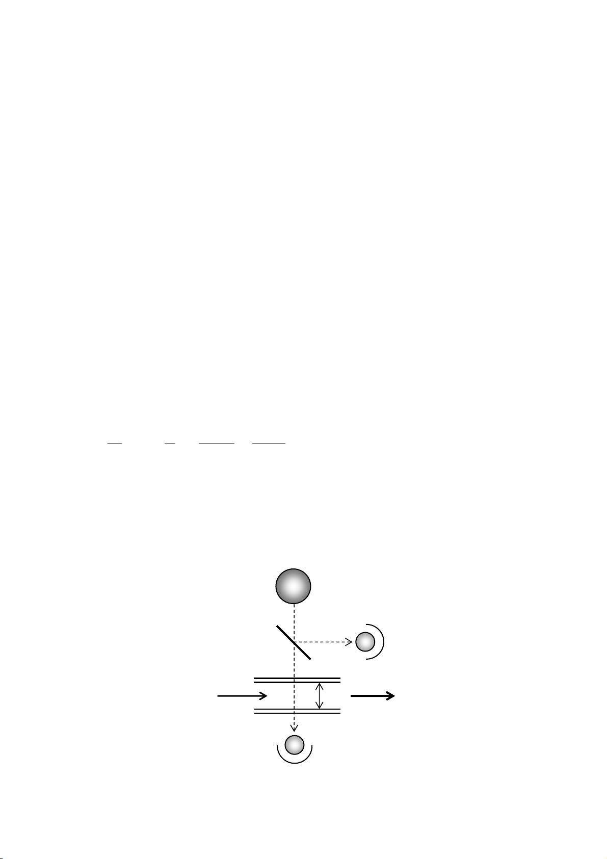
2. Measuring principle
This Analyzer is an UV absorption type ozone analyzer, which will detect and measure quantity
of UV ray absorbed by ozone in the sample gas introduced into the detector.
A low-pressure mercury lamp (emission wavelength 253.7 nm) is used for its light source and the
quantity of light absorbed by ozone existing within the optical path 'T' obeys the Lambert-Beer's
Law, so the concentration of ozone can be measured as follows. In addition, since the
measurement is affected by temperature and pressure, the measured values need to be corrected
under each situation using the following compensation formula.
C = A
αT× log
Io
Ix × 273 + t
273 × Po
P + Po
where: C : Concentration of ozone
α: Absorption coefficient of ozone
T : Optical path length (Cell gap)
Io : Incident UV light intensity
Ix : Transmitted UV light intensity
A : Constant
t : Gas temperature
Po : Atmospheric pressure
P : Gas pressure
Figure- 1 Logic Diagram
Ozone
Sensor 2
Sensor 1
T
Low-pressure
mercury lamp
IN
Ozone
OUT

EOP-D73-001-7-002-05E
E.J. OZONE PRODUCTS - 14 -
3. Specifications
(1) High Concentration Ozone Analyzer
Model: ME810 (Type S, Type R)
Measuring principle: UV absorption method
Detection target: Generated ozone gas
Measuring Ranges: Select from the following ranges
0–15.0, 0–20.0 * unit: wt% (O2)
0–10.0, 0–20.0, 0–40.0 * unit: g/m3(N)
0–50.0, 0–100, 0–200
0–300
Measurement cycle: Continuous measurement
Sampling method: Pumped utilizing the supply pressure
Materials in contact
with gas:
SUS316, SUS304, PTFE, PCTFE, Quartz Glass, Pyrex glass,
Alumina, Fluorine-series resin, FFKM, etc.
(Zero gas line) SCS13A, Brass, Carbon steel, Zinc alloy, Nylon, PVA, FEP, PE,
NBR, HNBR, Glass fiber, PTFE, SUS304, etc.
* Ozone scrubber: Decomposing catalyst, FKM, Felt (Type S only)
Note: If the sample gas contains substances except ozone, the portions inside of the analyzer that
are exposed to gas may be eroded, damaged, or clouded. Please note that failures or
non-measurable state resulting from such damage are not included in the warranty even
during warranty period.
Sample Flow Rate: 0.5–1.0 L/min (0.5 L/min recommended)
Normal Operating
Pressure:
0.01–0.10 MPa(G) (internal supply pressure of piping of the analyzer)
(pressure when the adjustment valve is fully open)
Maximum Pressure: 0.2068 MPa(G) or less
(supply pressure of the analyzer: 30 psig or less)
Outlet Pressure: Atmospheric pressure
Span drift: Within ±1% FS/month
Zero drift: Within ±1% FS/month (Refer to the Note below.)
Note: Need to perform Zero calibration by integrated timer once
every 24 hours.
Use a gas not contained ozone, not be polluted (dry) as a zero
calibration gas.
Linearity: Within ±1% FS
Repeatability: 0.2% FS or less
Zero Adjustment: Zero calibration by integrated timer is performed once every 24 hours
(in automatic operation).
* Based on zero/interval setting

EOP-D73-001-7-002-05E
E.J. OZONE PRODUCTS - 15 -
Display: Main display: Red/Green 7 Segment LED (4 digits)
Sub display: Red 7 Segment LED (4 digits)
MODE: 5 LED Lamps
MES (MEASUREMENT): Stays on during measurement / blinks
during zero calibration
ALM (ALARM1, 2): Blinks at occurrence of an alarm
ERR (ERROR): Blinks at occurrence of analyzer error
CHK: Turns on when check is being conducted / blinks during setting
mode
TES: Turns on when test is being conducted
UNIT: LED Lamp
Span Adjustment: Performed by digital setting (0.000-2.000)
Analyzer Output: Relay contact output: dry contact
• Measurement signal: output only when the measurement is
progressing normally
• Concentration alarm: any single-level alarm setting is available;
2 systems
• Analyzer error signal: output when an abnormal condition occurs
Contact rating: 250 V AC 5 A (resistance load)
250 V AC 1.5 A (induction load)
30 V DC 5 A (resistance load)
30 V DC 1.5 A (induction load)
MEASUREMENT: Measurement signal (c contact)
ALARM 1: Concentration alarm 1 signal (c contact)
ALARM 2: Concentration alarm 2 signal (c contact)
ERROR: Analyzer error signal (a contact)
Analyzer Input: Zero calibration input signal (insulation output)
Analog Output: 0–1 V DC, 0–10 V DC
1–5 V DC, 4–20 mA DC
One of the above is to be selected.
* The load resistance connectable externally is 10 kor more for
voltage output, and 550 or less for current output.
Self-diagnosis
Function:
Light source abnormalities, cell contamination, sensor abnormalities,
internal circuit abnormalities, and measurement accuracy analysis
results are detected and displayed.
Test Mode: Analog output, alarm contact, solenoid valve operation, and contact
input can be tested.
Power Supply: 100–240 V AC ±10%, 50/60 Hz
Power Consumption: 55 VA or less
Dimensions: 321 (W) × 428 (H) × 202 (D) [mm]
* Protruding parts are not included in these dimensions.
Equivalent to NEMA4x (IP65)

EOP-D73-001-7-002-05E
E.J. OZONE PRODUCTS - 16 -
Mass: Approximately 15 kg
Pipe Port:
(sample inlet (S type,
R type), zero gas inlet
(R type))
Rc 1/4'' socket
* In the case of connecting the sample gas that can be measured without
problems and has undergone pretreatment (having adjusted the flow
rate and having removed dust and so on), without using the accessory
filter and valve assembly or zero gas and valve assembly (R type).
Pipe ports diameter:
(sample gas inlet)
Select one from the following pipe ports diameter
Ø1/4 inch, Ø3/8 inch, Ø6 mm, Ø10 mm (sample gas inlet)
* In the case of using the accessory filter and valve assembly or zero
gas and valve assembly (R type).
Wire Ports: Power supply/control cable port: Ø9 mm–Ø22 mm
Signal cable port: Ø4 mm–Ø12 mm
Ambient temperature: 0°C–45°C
Relative humidity: 90 % RH or less within the case (no condensation)
Temperature
compensation:
Measurement range: 0°C–50°C
Temperature compensation: 0°C (Switchable to 20°C compensation)
Others: Warm-up time is settable for duration of 0 to 99 minutes
(default:10minute)
♦Option
Pressure compensation: Compensation range: 80–130 kPa (abs) (optional)
Pressure sensor (Measurement range: 0.35 MPa (abs))
(2) Off-gas Ozone Analyzer
Model: ME820 Type S
Measuring principle: UV absorption method
Detection target: Exhaust ozone gas
Measuring ranges: Select from the following ranges
0–10.0, 0–20.0, 0–40.0 *unit: g/m3(N)
0–50.0, 0–100
0–1000, 2000 *unit: ppm
Measurement cycle: Continuous measurement
Sampling method: Suction by internal pump
Materials in contact
with gas:
SUS316, SUS304, PFA, PTFE, PCTFE, PVDF, PVC, Quartz glass,
Alumina, Fluorine-series resin, FKM, Glass fiber, Sapphire, etc.
(Zero gas line) PVA, FEP, PE, NBR, PBT, POM, HNBR, FKM, SUS304, PVDF,
EPDM, Phenol resin, Felt, Pyrex glass, Glass fiber, Brass, Carbon
steel, Zinc alloy, Nylon, TYGON®, etc.
* Ozone destruct: Decomposing catalyst, FKM, Felt

EOP-D73-001-7-002-05E
E.J. OZONE PRODUCTS - 17 -
Note: If the sample gas contains substances except ozone, the portions inside of the analyzer that
are exposed to gas may be eroded, damaged, or clouded. Please note that failures or
non-measurable state resulting from such damage are not included in the warranty even
during warranty period.
Sample Flow Rate: 1.0–2.0 L/min (1.0 L/min recommended)
Maximum Pressure: Within ±10k Pa(G) (0.10 M Pa(G) or less without a sampling pump)
Outlet Pressure: Atmospheric pressure
Span drift: Within ±1% FS/month
Zero drift: Within ±1% FS/month (Refer to the Note below)
Note: Need to perform Zero calibration by integrated timer,
performed once every 24 hours. Use a gas not contained ozone,
not be polluted (dry) as a zero calibration gas.
Linearity: Within ±1% FS
Repeatability: 0.2% FS or less
Zero Adjustment: Zero calibration by integrated timer performed once every 24 hours
(in auto operation)
* Based on zero/interval setting
Display: Main display: Red/Green 7 Segment LED (4 digits)
Sub display: Red 7 Segment LED (4 digits)
MODE: 5 LED Lamps
MES (MEASUREMENT): Stays on during measurement / blinks
during zero calibration
ALM (ALARM1, 2): Blinks at occurrence of an alarm
ERR (ERROR): Blinks at occurrence of analyzer error
CHK: Turns on when check is being conducted / blinks during setting
mode
TES: Turns on when test is being conducted
UNIT: LED Lamp
Span Adjustment: Performed by digital setting (0.000–2.000)
Analyzer Output: Relay contact output: dry contact
• Measurement signal: output only when the measurement is
progressing normally
• Concentration alarm: any single-level alarm setting is available;
2 systems
• Analyzer error signal: output when an abnormal condition occurs
Contact rating: 250 V AC 5 A (resistance load)
250 V AC 1.5 A (induction load)
30 V DC 5 A (resistance load)
30 V DC 1.5 A (induction load)
MEASUREMENT: Measurement signal (c contact)
ALARM 1: Concentration alarm 1 signal (c contact)
ALARM 2: Concentration alarm 2 signal (c contact)
ERROR: Analyzer error signal (a contact)

EOP-D73-001-7-002-05E
E.J. OZONE PRODUCTS - 18 -
Analyzer Input: Zero calibration input signal (insulation output)
Analog Output: 0–1 V DC, 0–10 V DC
1–5 V DC, 4–20 mA DC
Select one from the above.
* The load resistance connectable externally is 10 kor more for
voltage output, and 550 or less for current output.
Self-diagnosis
Function:
Light source abnormalities, cell contamination, sensor abnormalities,
internal circuit abnormalities, and measurement accuracy analysis
results are detected and displayed.
Test Mode: Analog output, alarm contact, solenoid valve operation, and contact
input can be tested.
Power Supply: 100–240 V AC ±10%, 50/60 Hz
Power Consumption: 55 VA or less
Dimensions: 321 (W) × 428 (H) × 202 (D) [mm]
* Protruding parts are not included in these dimensions.
Equivalent to NEMA4x (IP65)
Mass: Approximately 15 kg
Pipe Ports:
(sample inlet, sample
exhaust outlet)
Rc 1/4'' socket
* Sample inlet: In the case of connecting the sample gas that can be
measured without problems and has removed moisture, without
using accessory filter and valve assembly.
Pipe Ports diameter:
(sample gas inlet)
Select one from the following
Ø3/8 inch (Ø10 mm), switchable between Ø1/4 inch and Ø3/8 inch,
switchable between Ø5/16 inch and Ø3/8 inch
* In the case of using accessory water trap
Wire Ports: Power supply/control cable port: Ø9 mm–Ø22 mm
Signal cable port: Ø4 mm–Ø12 mm
Ambient temperature: 0°C–45°C
Relative humidity: 90 % RH or less within the case (no condensation)
Temperature
compensation:
Measurement range: 0°C–50°C
Temperature compensation: 0°C (Switchable to 20°C compensation)
Others: Warm-up time is settable for duration of 0 to 99 minutes
(default: 10minutes)
♦Option
Pressure compensation: Compensation range: 80–130 kPa (abs) (optional)
Pressure sensor (Measurement range: 0.35 MPa (abs))

EOP-D73-001-7-002-05E
E.J. OZONE PRODUCTS - 19 -
Protective cover
: Optional parts
4. Names of each part and description of functions
(1) High Concentration Ozone Analyzer Type S
Figure- 2 Names of each part of ME810 Type S
[21] [22]
[20]
[1]
[3]
[42]
[49]
[5]
[4]
[2]
[6]
[7]
[3]
[33]
[32]
[34]
[42]
[41]
[8]
[6]
[2]
[9]
[C]
[7] [51] [15]
[16]
[10]
[14]
[13]
[24][11][19][17][18][12][23]
[41][27]
[50]
[47]
[26]
[25]
[B]
[A]
Table of contents
Popular Measuring Instrument manuals by other brands


Mirion Technologies
Mirion Technologies DMC 3000 user guide

Konica Minolta
Konica Minolta AeroDR System Operation manual

BURG WATCHER
BURG WATCHER ProfiScale CROSS operating instructions

Precision Digital Corporation
Precision Digital Corporation PROVU Series manual

PFlow Industries
PFlow Industries P117 instruction manual

vse
vse VSI 0.04 operating manual


