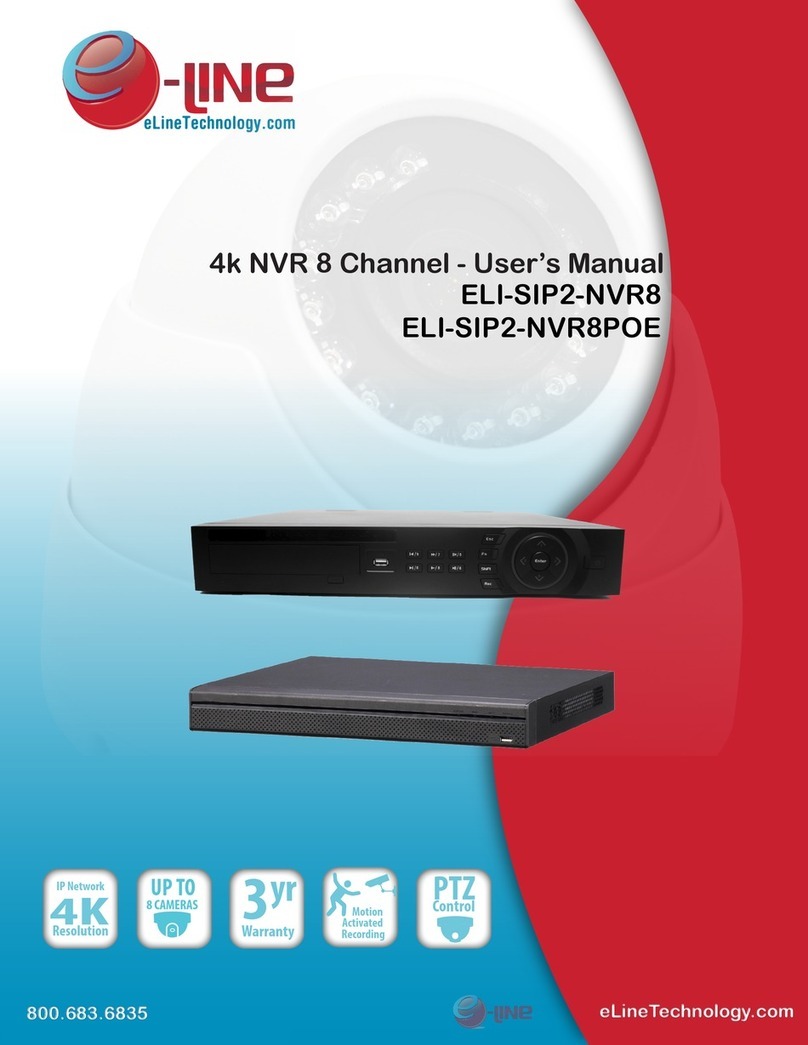
E-line ELI-SIP2-NVR32 User manual

- 1 -
About this Document
Purpose
This document describes the features, hardware installation, network access, network
configuration, routine maintenance, fault analysis, and troubleshooting of the Network
Video Recorder (NVR).
Intended Audience
This document is intended for:
Technical support engineers
Maintenance engineers
Symbol Conventions
The symbols that may be found in this document are defined as follows.
Symbol
Description
Alerts you to a high risk hazard that could, if not avoided,
result in serious injury or death.
Alerts you to a medium or low risk hazard that could, if
not avoided, result in moderate or minor injury.
Alerts you to a potentially hazardous situation that could,
if not avoided, result in equipment damage, data loss,
performance deterioration, or unanticipated results.
Provides a tip that may help you solve a problem or save
time.
Provides additional information to emphasize or
supplement important points in the main text.
Important Statement
Users are required to enable and maintain the lawful interception (LI) interfaces of
video surveillance products in strict compliance with relevant laws and regulations.
Installation of surveillance devices in an office area by an enterprise or individual to
monitor employee behavior and working efficiency outside the permitted scope of the
local law and use of video surveillance devices for eavesdropping of illegal purposes
constitute behaviors of unlawful interception
.

- 2 -
Contents
1 Specification .........................................................................................................- 3 -
2 NVR networking solutions................................................................................- 5 -
3 Hard drive .............................................................................................................- 7 -
3.1 Hard disk recommended ............................................................................................. - 7 -
3.2 Days of recorded ........................................................................................................ - 7 -
3.3 Installation .................................................................................................................. - 8 -
4 Basic operation ...................................................................................................- 10 -
4.1 Front panel description ............................................................................................. - 10 -
4.2 Rear panel description .............................................................................................. - 11 -
4.3 Startup ...................................................................................................................... - 12 -
4.4 Shutdown ................................................................................................................. - 13 -
4.5 Login ........................................................................................................................ - 13 -
5 Quick setup.........................................................................................................- 15 -
6 Live Video ...........................................................................................................- 21 -
7 Video Playback ..................................................................................................- 25 -
7.1 Video Playback ......................................................................................................... - 25 -
7.2 Video Backup ........................................................................................................... - 26 -
8 F.A.Q ....................................................................................................................- 30 -

- 3 -
1 Specification
System
CPU
SOC
Operation
system
Embedded Linux 2.6
features
Embedded CMS system, fully functional friendly interface, easy to use;
Original "quick configuration" feature that enables NVR configuration and
management operations easy to get started.
Original "camera private network enables Plug-and-play camera access auto
detection and schedule setup for fast rapid use.
Real-time fault alarm mechanism to timely reporting of hard disks, networks,
fault information, such as camera disconnection; Embedded WebServer using
Flash technology to support common browsers real-time monitoring and
playback
Video
Ability to
decode
Support H.264 High profile Level5.0 decode
Support resolution up to 5 megapixel
Real-time
video
Single screen: 5 megapixel /3megapixel /1080P/720p/D1 resolution
Quad display of 1080P/720p/D1 resolution
Split screen 1/4/8/16.for D1 resolution
Audio format
G711_A/G711_U
record
Record info
Support 32ch recording, Maximum recording bandwidth is 144Mbps
Support resolution: 5 mega,3 mega, 1080p, 720p/D1 resolution.
HDD
Support four 1.5/3.0Gbps SATA hard disks,Maximum capability of single
hard disks is 4TB.
recording
days
4 hard disks, maximum 4*4TB hard disk support.
Playback
Support 4ch 1080P playback at the same time.
Backup
Support U drive, mobile HDD, network backup disk.

- 4 -
display
interface
One VGA output interface, one HDMI output interface, support homology
display
resolution
1024x768、1280x720、1920x1080
Network
interface
Two RJ45 10/100/1000Mbps network port
Network
protocol
RTP/RTCP,TCP/UDP,HTTP,DHCP,DNS,NTP
others
Environment
temperature
10℃—50℃
Environment
humidity
5%-90%
power supply
AC110/220V,47-63HZ,Maximum consumed power is 200W.
consumption
Low-power design, Maximum motherboard power consumption 15w (without
USB interface), with 4*4T hard disk increases 40W power consumption.
Size
chassis:440mm x 435mm x 89.8mm(L*W* H)
weight
Net weight 6.805kg,with packaging 8.975kg
USB interface
2*USB2.0 host interface;Respectively as backup and USB mouse.

- 5 -
2 NVR networking solutions
This the NVR has two Ethernet ports LAN1 and LAN2. Supports the private network
of the cameras, and 2nd one for WAN local remote connections. LAN2 is used for
network devices for automatic detection within the NVR software.
Option One:Private Network Setup
Camcorder network is a network exists only network cameras and NVR, there is no
other network equipment, and this network is dedicated to the NVR and network
cameras, audio and video transmission. Dedicated camera network must be connected
with the NVR LAN2, and ensure that the LAN2 camera network functions are enabled
(factory default enabled detailed configuration, see "Network Video Recorder User
Manual quick configuration through LAN1 access NVR.
10M/100M/1000Mbps RJ45 Internet port
For connecting the Internet or local network, And NVR need to search the camera by
manually.
The camera dedicated network topology shown in Figure 2-1
Figure 2-1 camera dedicated network

- 6 -
Option II:Open network.
The open network refers to the network in addition to the network cameras and NVR,
there can be other network devices, network topology can be free to organize, just need
to ensure communication between the NVR and network camera is smooth. In the use
of the network, LAN2 needs to turn off the camera dedicated network.
Open network, the need to manually search for and add network cameras, see detailed
operation quickly configure.
Open network topology shown in Figure 2-2.
Figure 2-2 open network topology

- 7 -
3 Hard drive
Formatting will clear all clear video data on disks, please pay attention to this
function
Before removing a hard disk from the NVR during operation, unload the disk,
otherwise. The disk may be damaged.
Please supply stable power supply, otherwise the disk may be damaged or loss of
data.
Maximum capacity of single hard drive is 4TB.
Suggest to use more than two hard drive to achieve the performance balance,
3.1 Hard disk recommended
Given the current market of different brands, the uneven quality of the different models
of hard, recommended to use Seagate or Western Digital brands which are designed for
security/server applications offering 24x7 reliable operations.
Recommended model: Western Digital’s WD AV-GP and Seagate’s SV-35 SERIES
3.2 Days of recorded
Calculate recording days:
Firstly: Use the formula 1 to calculate the recording capacity q that one channel
record need each hour
q= d ÷8×3600÷1024 (formula 1)
Secondly: calculate the recording days
w– Single capacity of single hard drive, Unit ( MByte)
n – Hard drive count
h – Recording time within a day

- 8 -
c – Recording approaches of NVR
For example: calculate detail recording day
Calculate recording days
Hard drive
capacity
Video stream
cameras
Days recorded
4×4TB
D1 1.5Mbps
32
30 days
4×4TB
720p 3Mbps
32
15 days
4×4TB
1080p 4.5Mbps
32
10 days
3.3 Installation
The hard specific installation steps are as follows:
Step 1 Take out the screws of the cover and the cover

- 9 -
Step 2 Hard drive inset to the PCB SATA interface,
Step 3 Fixed hard drive with 4 screws,
Repeat the step2, step3, untill all the hard drive are installed, and then cover the upper
cover,fix the screw.s
End----

- 10 -
4 Basic operation
4.1 Front panel description
Figure 4-1 Front panel
Table 4-1 Front panel
No
Name
Description
1
KB/MOUSE
For connecting external mouse, keyboard.
2
BACKUP
For connecting U drive and mobile HDD.
3
HDD 1~4
1~4 hard drive work indicating lamp (blue)
Long light when it’s alive, the blue light flashes when it
reading and writing data.
4
SYS
NVR running indicator lamp (red), long light when it is
behaving normally.
5
PWR
NVR power indicate lamp (red), long light after startup.
6
POWER
Power on/off button
Hard drive working indicate light correspond to the internal hard drive, which is shown
in the following table.
HDD1
HDD2
HDD3
HDD4

- 11 -
4.2 Rear panel description
Figure 4-2 shows the rear panel of the network video recorder. Table 4-2 shows the
interface of rear panel,
Figure 4-2 Rear panel
Table 4-2 Real panel description
No
Name
Description
1
Ground connector
Safety GND connect
2
Power switch
Power input switch
3
Power interface
AC110/220V power supply interface
4
OUT
1 alarm output channel (switch value)
IN
1 alarm input channel (switch value)
RS485
1 channel RS485
5
Audio input
Connect microphone linear audio
6
Audio output
Linear audio output
7
RESET button
Keep click the button more than 5 seconds to restore
factory setting
8
HDMI interface
HDMI output
9
HDMI and VGA
Double screen
display mode
MON CLONE: use for Homologous double screen
display output.
MON EXTEND: use for non-homologous double
display output
10
VGA interface
VGA video display output
11
G-LAN2 interface
RJ45 10/100/1000Mbps adaptable Ethernet interface
12
G-LAN1 interface
RJ45 10/100/1000Mbps adaptable Ethernet interface.

- 12 -
The No 4,5,9 in the table are functions formerly reserved, temporarily not opened to use.
4.3 Startup
Ensure that a power supply is connected to the NVR correctly.
Before starting the NVR, ensure that a monitor is connected to the HDMI or VGA
interface of the NVR correctly.
If the power indicator on the front is off, connect a power supply and turn on the power
switch on the rear panel to start the NVR. If the power indicator on the front is steady
in red, press the off/on button on the front panel to start the NVR, the NVR conducts a
self-test and then display the result on the screen。
When an abnormality is detected and the self-test screen stays on, choose to continue or
shut down in the lower right corner of the screen. If you choose to continue, the NVR
enters the login interface.
The hard disk(s) required by the NVR must be provided by users. Hard disk detection is
performed during startup. If the detection fails, check whether it is caused by the following
causes:
The hard disks are new and unformatted. In this case, format the hard disks.
The hard disks are formatted, but the file system is inconsistent with the one supported
by the NVR.
The hard disks are damaged.

- 13 -
4.4 Shutdown
Do not cut off the power supply when the system prompts "Shutting down".
When the NVR is operating, avoid cutting off the power by turning off the power
switch on the rear panel or removing the power cord.
The NVR may not operate normally when a power supply exception occurs, likely
causing damage to the NVR in serious conditions. In such a circumstance, you are
advised to use a regulated power supply.
To shut down the NVR before logging in, press and hold the PWR button on the front
panel for over 3s. The NVR is closed successfully when the power indicator on the
front panel changes from steady on to flashing in red.
To shut down the NVR after logging in to the main interface, click in the upper
right corner or press and hold the PWR button on the front panel for over 3s. The
shutdown interface appears, as shown in Figure 4-3.
Figure 4-3 Shutdown interface
Enter a valid password and click Shutdown. When authentication is successful, the
prompt "Are you sure to shut down?" is displayed. Click Yes.
4.5 Login
Take the following steps to log in to the NVR:
Step 1 Enter your user name and password on the login interface of the NVR.

- 14 -
Figure 4-4 Login interface of the NVR
The super user is admin and the password is also admin, both of which are case-sensitive.
Change the password after logging in to the NVR for the first time. When a user enters
incorrect passwords three times within an hour during login, the account is locked. For how
to unlock the account, see section “Network Video Recorder user manual".
Step 2 Click Login to enter the main interface.
----End

- 15 -
5 Quick setup
Quick setup is intended to group together some frequently used functions to facilitate
the configuration management of NVR. For the NVR, the quick setup functions cover
the network configuration, disk configuration, data and time configuration, webcam
search, and video configuration of the NVR. For the cameras added to the NVR, the
quick setup functions cover the network configuration, code stream configuration, and
motion detection configuration of the cameras. Figure 5-1 shows the Quick Setup
interface.
Figure 5-1 Quick Setup interface
Description of the Quick Setup interface
Section 1:
NVR basic information
Set the name of the NVR and change the date and time.
Synchronize the time of cameras manually or automatically.

- 16 -
If you select the manual mode, click for time synchronization. If you select the
auto mode, the NVR synchronizes the time of cameras automatically.
Section 2: NVR network configuration
One default IP address of the NVR is 192.168.0.121, another IP address default
is192.168.1.121 when network interface 2 is used.
Parameters such as the IP address, subnet mask, default gateway, and DNS address
can be set in basic network configuration. The network connection status and speed
are displayed in real time.
Network interface 2 of the NVR supports the camera-dedicated network function
(enabled by default).
A camera-dedicated network is a network where only webcams and the NVR exist.
After the camera-dedicated network function is enabled, the NVR does the following:
Enables the DHCP service and assigns IP addresses to webcams automatically (the
DHCP function is enabled on the webcams).
Searches for webcams in the network.
Adds the searched webcams automatically and enables 24/7-hour video recording.
Figure 5-2 shows the topology of the camera-dedicated network.
Figure 5-2 Topology of the camera-dedicated network

- 17 -
Section 3: hard disk management
Formatting will clear all video data on hard disks.
Before removing a hard disk from the NVR during operation, unload the disk;
otherwise, the disk may be damaged.
Manage the hard disks of the NVR as follows:
To format a hard disk, click Format. In the confirmation dialog box, click Yes. It
takes about 10 minutes to format a 2 TB hard disk.
Load or unload hard disks. Before removing a hard disk from the NVR, unload the
hard disk.
Modify a hard disk group.
Check the statuses of hard disks (normal, abnormal, unformatted, and unavailable).
Check the available space and total space of hard disks.
Section 4: camera quantity alarm
The NVR searches for webcams in the network automatically when the
camera-dedicated network function is enabled.
When the number of webcams does not exceed the management capability of the
NVR, the NVR adds the webcams automatically.
When the number of webcams exceeds the management capability of the NVR, the
NVR adds random webcams based on its management capability automatically.
The remaining webcams cannot be added and an alarm is generated, as shown in
Figure 5-3.
Figure 5-3 Camera discovery prompt
Select cameras managed by the NVR. If you click Ignore, the webcams currently
managed by the NVR are used. If you click Select, the Camera Search interface
appears, as shown in Figure 5-4.
A webcam is discovered. Ignore or Select.

- 18 -
Figure 5-4 Camera Search interface
Select webcams and click Ok.
Section 5: searching and deleting cameras
When the camera-dedicated network function is not enabled, click Search Camera to
search for webcams manually. The Camera Search interface appears, as shown in
Figure 5-5.
Figure 5-5 Camera Search interface

- 19 -
Click . The Camera Search interface (shown in Figure 5-4) appears. Select
cameras and click Ok.
To remove managed cameras, check the check box in the camera list,
select the cameras to be removed, and click Delete Camera.
Section 6: Management of the authentication accounts of cameras
Only successfully authenticated cameras can be used normally. Before adding a camera,
add the authentication account and password of the camera to the corresponding list.
To log in to a webcam, enter the corresponding authentication account. Only
successfully authenticated webcams can be added.
The system provides the default account admin and default password admin. Click
to add a camera authentication account.
To delete a camera authentication account, select the account and click .
Section 7: camera setup
This section displays the statuses of webcams and provides setting of the names, IP
addresses, record policies, code streams, and motion detection of webcams.
The statuses of webcams include Online, Offline, and Account error.
To view live videos, click following an online webcam.
Change the name of a webcam.
Enter a new name in the Name column.
Modify the IP address of a webcam.
1. Click the IP address to be modified. The Camera IP Setup dialog box appears.
2. Enter a new IP address. For details, s
Set a record policy.
1. Click the record policy to be modified. The Record policy Configuration
dialog box appears.
2. Enter a new record policy. For details,.
Set a code stream.
1. Click the code stream to be modified. The Stream dialog box appears, as shown
in Figure 5-6.
2. Enter a new code stream, set Apply to All Devices to On, and click OK.
The parameter settings are applied to all webcams with the same resolution.

- 20 -
Figure 5-6 Stream dialog box
Set a motion detection alarm.
1. Click the motion detection information to be modified. The Motion Alarm
dialog box appears.
2. Set the deployment time and detection zone if the motion detection alarm
function is enabled.
Table of contents
Other E-line Network Hardware manuals
Popular Network Hardware manuals by other brands

Cabletron Systems
Cabletron Systems FDCMIM-24 installation guide

Atlantic
Atlantic Cozytouch instructions

Endress+Hauser
Endress+Hauser eco-graph operating manual

Avaya
Avaya 1101GT Installation Job Aid

UNICORECOMM
UNICORECOMM UM620N user manual

Cisco
Cisco 6500 - Catalyst Series 10 Gigabit EN Interface Module... Configuration guide

MIKRODEV
MIKRODEV XIO110-E0N-GD6-B2000 Hardware manual

ZyXEL Communications
ZyXEL Communications ZyWALL SSL 10 quick start guide

Siemens
Siemens RUGGEDCOM RX1400 installation guide

Phihong
Phihong POE125U user manual

KVM-TEC
KVM-TEC KT-6936 Quick installation

ADTRAN
ADTRAN Total Access 300 Series quick start guide