E-one Dilution SOLUTIONS MDE0110MF.75KIT User manual

eOneeOne
3/4”
MICRO-DOSER KIT
Item #: MDE0110MF.75KIT
MANUAL
Scan this QR code
for digital instructions
and support videos

PACK
Part Item Number Qty Part Image
¾” Mixing Chamber MC34 1
Mixing Chamber Sunshade MC34-SHADE 1
PACK
Part Item Number Qty Part Image
¾” Threaded Union BK034-U 2
¾” Check Valve CV34-PH 1
¾” Tee TT34 1
¾” to ½” Reducer Bushing RB75-50ET 1
¾” Close Nipple NIP075-2 3
Thread Tape TEF12 1
Digital Instructions and
Support Videos QR Tag TAG-MD 1
Included in the MicroDoser ¾” Kit:
¾” Micro-Doser Kit
Contents
PACK
Part Item Number Qty Part Image
Water Meter with Adapters
(1 pulse per 1 gallon) WM34-1PPG 1
A
gaskets nuts
adapters
water meter
B
C

eOneeOne 1
PACK
Part Item Number Qty Part Image
eOne MF 0110 PEU483891MEA 1
tubing kit
eOne pump
E
PACK
Part Item Number Qty Part Image
Pressure Relief Anti-Siphon
Valve Assembled Kit 4x6
with Wall Bracket
PRV4X6 1
Syringe Kit 07944-KIT 1
D
Included for dicult priming situations only.
NOTE: Parts ordered, or pictured, may look slightly dierent than the image displayed,
but the t and function will be the same.

2
INSTRUCTION TO ASSEMBLE THE MICRO-DOSER KIT PLUMBING SECTION
Remove the white clear caps from the ends of the
Water Meter, and discard.
To attach the Adapters to the ends of the Water
Meter, slide the Adapter through the Nut. Place the
Gasket between the Adapter and the Water Meter
threads, as indicated in the image. Hand tighten
the Nut.
Wrap Thread Tape 4 to 5 times on all threads,
except on the PRV Adapter Kit parts. Make sure to
wrap tape clockwise to prevent from unraveling.
Attach a Union to the inlet side of the Water Meter.
Make sure the arrow on the Water Meter is pointing
in the direction of the ow.
Attach the Check Valve to the outlet side of the
Water Meter. Make sure the arrow on the Check
Valve is pointing in the direction of the ow.
Attach a Close Nipple to the Check Valve.
12
3 4
¾” Micro-Doser Kit
Step-by-Step Assembly Instructions
5 6

eOneeOne 3
Attach the Tee to the Nipple and attach a second
Nipple to the opposite end of the Tee.
Thread the Reducer Bushing into the top opening
of the Tee.
Attach the Mixing Chamber to the Close Nipple.
Make sure the arrow on the Mixing Chamber
points in the direction of the ow.
Insert the third Close Nipple in the outlet of the
Mixing Chamber, and attach the last Union to the
other side of the Close Nipple.
The Plumbing Assembly of your Etatron Micro-Doser ¾” System is complete. Put the Assembly aside and
continue with the Pressure Relief Valve (PRV).
78
9 10
¾” Micro-Doser Kit
Step-by-Step Assembly Instructions
11

4
For these steps you will need the PRV4X6 kit & the Etatron eOne MF Pump
Take the PRV4X6 kit out of the box. The outer holes
on the bracket are used for mounting the PRV4X6
to a surface. Those need to be drilled out to
accommodate ¼” screws/bolts.
Take your pump from its box and mount it on the
wall using the bracket included with the pump. Grab
the Opaque Rigid Polyethylene Discharge Tube
(ORPDT) included with the pump, and cut it in half
(if cut too short the tension may cause leaks).
Connect each one of the tube’s halves to the
Adapters on the PRV (see Steps 14 - 15).
To attach the tubes to the PRV, insert the tube
through the outside opening of PRV Nut. Insert the
Locking Collar making sure the Collar’s crown
points away from the Nut. Now, insert the Nozzle
in the tube’s opening. Push the Collar and Nozzle
together as close as possible. Repeat for the other
tube half.
Now attach the ORPDT to the Adapters on the
PRV using the Nuts.
12 13
14 15
Assembly & Connection of the PRV
to the Etatron Pump
(ORPDT)
Opaque Rigid
Polyethylene
Discharge Tube
ow
LOCKING
COLLAR
TUBE
NUT
NOZZLE
TUBE
NUT
COLLAR &
NOZZLE

eOneeOne 5
Grab the other end of the ORPDT on the inlet side
of the PRV, and attach it to the Discharge Valve of
the pump’s head. Follow instructions in steps 14-15
to attach the tube.
Mount the PRV to the wall or surface using 1/4”
screws/bolts. Make sure the tube runs with no
tension from the pump to the PRV.
Grab the Injection Valve from the pump box. Cut
the tip of the valve to the threads level, see image.
Insert the Injection Valve into the Reducer
Bushing at the top of the Tee in the Micro-Doser
Plumbing Assembly, hand tighten only.
Anchor the Micro-Doser Plumbing Assembly to
the wall or surface, right underneath the pump.
Remove the Nut, Collar, and Nozzle from the top
of the Injection Valve, and attach the tube from
the outlet side of the PRV, following the same
procedure in step 16.
Your Micro-Doser Kit assembly is now connected
to your pump.
16 17
18 19
20
Discharge
Valve
PRV
inlet
PRV
outlet
21
cut here
for 3/4”
lines
ow ow

6
Attaching the Foot Filter and Priming Tubing
Grab the Clear
exible PVC Tube
included with your pump.
Cut the Tube in half,
one piece for the Priming
Valve and the other one
for the Suction Valve.
Attach the end of one of
the sections to the
Suction Valve and the
other end to the Foot
Filter, following
procedure in Step 14-15.
Make sure the Foot
Filter sits comfortably
in the chemical container.
Slide the second
section of the
Clear Flexible
PVC Tube onto
the Priming Barb.
Place the other
end of the tube
inside the
chemical container.
Next, connect
the pump to the
Water Meter
(see steps
26-31 below).
CONNECTING THE WATER METER - You will need a punch and a small at head screwdriver
To connect the pump to
the Water Meter, remove
the bottom front cover
from the pump, using a
at head screwdriver.
Remove the rubber
cap on the left.
Using a punch tool,
punch a small hole
through the rubber
cap.
Insert the Water Meter
wires through the hole
in the rubber cap.
Run the wires back
through the hole in the
front cover and reinsert
the rubber cap.
Insert the wires into
terminals 3 and 4 from left
(push the buttons to insert).
Make sure they are
connected properly
and secured.
22 23
24 25
26 27
Tubing Connection - Water Meter Wiring
28 29
30 31

eOneeOne 7
Priming the Pump
Plug in the pump,
the display will read
SETUP FW01 VFT.
Press the arrow
to the right to reach
FW03 MF.
Push the START/STOP button twice. Screen shows
OPERATING MODE/ MANUAL MODE.
Loosen the air
bleed nut. Push
the START/STOP
button to begin the
priming functions.
The pump will begin to
stroke/click.
Once the chemical
starts going down
the air bleed tube,
re-tighten the air
bleed nut
back up.
Chemical should
start going up
the discharge
tube and toward
the injection valve.
Push the START/STOP button to stop the priming
function once chemical reaches the injection valve.
Pump Priming
12
4
56
3
8
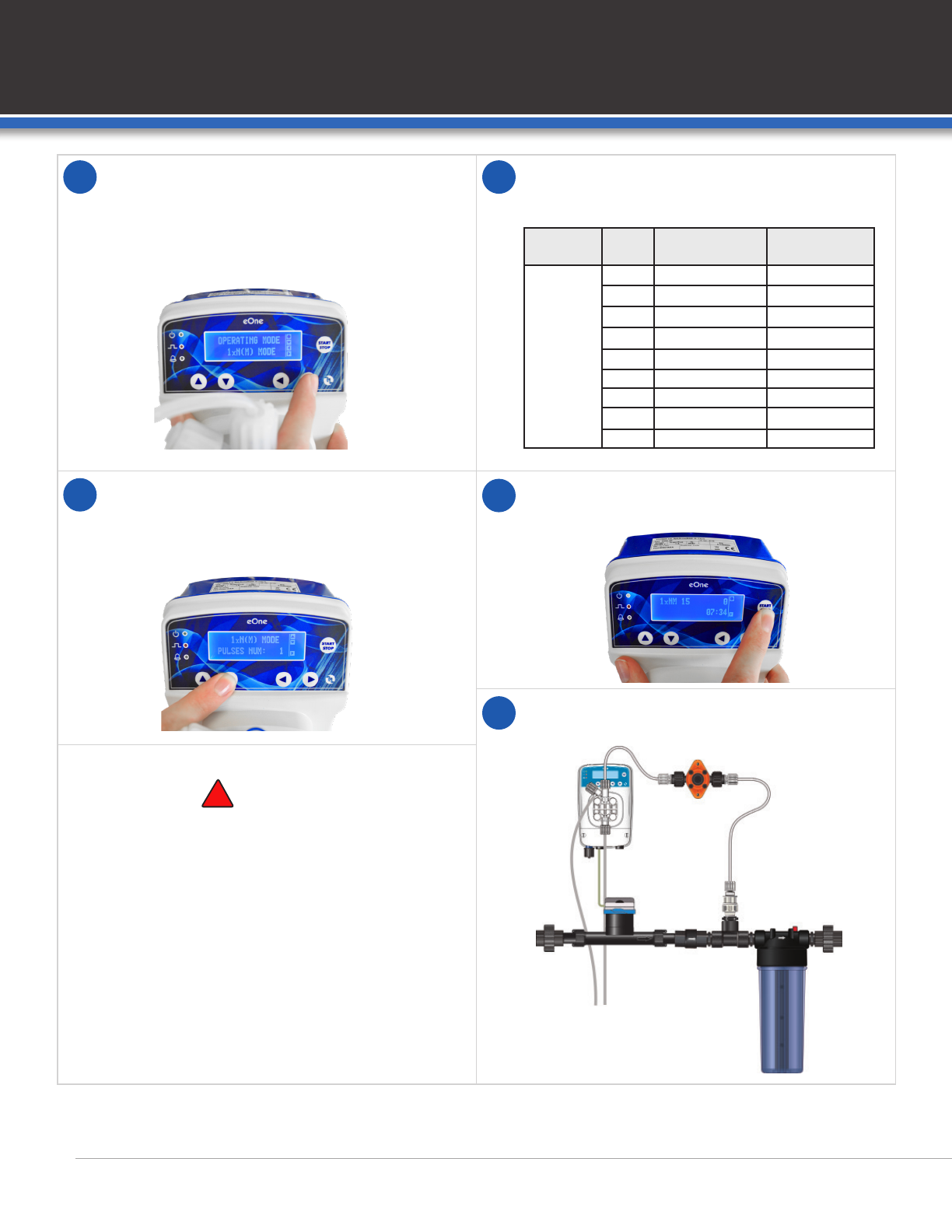
Push the right arrow until the display reads
OPERATING MODE/ 1 x N (M) MODE.
Please see page 9 for detailed instructions to
determine the Number of Pulses (N) Per Water
Meter Signal.
Pulse/Stroke Volume is calculated in relation to
the pressure in the irrigation line. Use the values
below to determine volume.
Push the down arrow to enter into the program.
Use the right arrow button to enter number of
pulses for each gallon of water. Press the down
arrow to save the settings.
Push the START/STOP button to begin the
program operation.
You can now turn on the irrigation water to begin
operation of the system using the water meter.
7 8
910
See operating manual for complete
instructions and safety standards.
When connecting a metering pump either to a
public water supply or to its own water source,
you must respect the regulations in force
concerning protection of the source
i.e. backflow prevention, etc.
!CAUTION
Micro-Doser Kit Installation
NEED HELP? CALL 1-800-451-6628
PUMP
MODEL PSI Single Pulse
Volume (mL)
Maximum
Volume (mL)
0110
30 0.23 41.4
35 0.22 39.6
40 0.22 39.6
45 0.21 37.8
50 0.21 37.8
55 0.20 36
60 0.19 34.2
65 0.19 34.2
70 0.18 32.4
Pump Programming
11

eOneeOne 9
Pump Calculations
Follow these steps to calculate the Number of Pulses Per Signal (N)
to reach a desired Injection Rate.
1. Identify operating pressure of system (Dynamic PSI).
2. Specify the volume of concentrate to be injected, per gallon.
3. Identify single pulse volume at the operating pressure identied in Step 1.
4. DIVIDE:
a. (Volume to be injected per gallon) / (Single Pulse Volume) = Number of Strokes
needed per gallon.
b. If this is not a whole number:
i. Chose closest whole number to set – variation from desired injection will be minimal,
but uctuations may be noticeable at very low or very high ow rates.
See “USING THE PRESSURE RELIEF VALVE” to decrease the Single Pulse Volume, to a volume
that divides evenly into the desired Volume to be injected per gallon.
Using the Pressure Relief Valve
Etatron eOne pumps should be installed
with a Pressure Relief Valve on the
injection line, between the pump and the
injection point.
This valve serves two purposes:
a. To vacuum relief in a siphon situation.
b. To make changes to the Single Pulse
Volume. Using the adjustment screw,
the amount of pressure that the eOne
pump experiences can be increased
above line pressure.
eOne
Pump
Pressure
Relief Valve
Injection
Point

10
To adjust the Single Pulse Volume with the Pressure Relief Valve (PRV), follow these steps:
Remove the Black Protection Cap from the PRV. Loosen the Counter Nut from the Adjustment Screw.
Turn Adjustment Screw clockwise to increase Back
Pressure, and reduce Single Pulse Volume.
Turn Adjustment Screw counter-clockwise to decrease
Back Pressure, and increase Single Pulse Volume
(back pressure cannot be adjusted to PSI lower than
dynamic pressure of water line).
Perform Volumetric test to determine/conrm
Single Pulse Volume (see VOLUMETRIC TESTING
PROCEDURE steps).
Repeat steps 3-4 as necessary until desired Single
Pulse Volume is reached.
12
3
45
Black
Protection
Cap Counter
Nut
Adjustment
Screw
Volumetric Testing Procedure
You can test check the amount of solution being injected by drawing concentrate from a graduated cylinder, with
MINIMUM 5 mL graduation, and at least 250 mL in total volume; then, run the pump for a set number of strokes.
All volumetric testing should be done with the pump fully primed and ready to operate. The pump should be in
STANDBY MODE.
Connect a hose
to the Test / Dump
Port on the water line.
Put the hose end in
the drain.
Fill a graduated
cylinder with
150 mL - 200 mL
of concentrate
solution.
12
Volumetric Testing Procedure
200 mL
To drain

eOneeOne 11
Place the suction strainer (Foot Filter) in the
graduated cylinder.
The suction strainer will displace ~50 mL.
Note the volume in the graduated cylinder with
the suction strainer.
Using buttons, set the pump to
MANUAL MODE.
Press button to enter the Mode Settings. Press button, the screen should read
PULSES / MINUTE - PULSES NUM: 300
Press buttons to set PULSES / MINUTE
to 100 (100 pulses / min).
Press the button, to save the new PULSE /
MINUTE settings.
Open Test/Dump Port to allow water ow.
GPM of water does not matter at this time, injection
will be done manually rather than proportionately.
Press the START / STOP button to activate the
pump. Run the pump for 1:00 Minute (use a timer).
34
5 6
250 mL
78
9 10
OPEN

12
Press the START / STOP button again to return
pump to STANDBY MODE
Close the Test/Dump Port to stop water.
The system should be ushed before entering /
returning to Operational Modes.
Note volume in graduated cylinder.
SUBTRACT:
DIVIDE:
Remove the suction strainer from the graduated
cylinder, and place the suction strainer back in the
concentrate container.
Return concentrate solution remaining in
graduated cylinder to concentrate container to
eliminate waste.
CLOSED
11 12
13 14
Starting Volume in
cylinder with
suction strainer
End Volume in
cylinder with
suction strainer
-=Total Volume
drawn in
100 Pulses
Example:
Volume
per Pulse
=
Total Volume drawn
in 100 Pulses
100 Pulses
0.2 mL
=
20 mL
100 Pulses
Example:
15 16

eOneeOne
Add the QR Code Tag and Sunshade to your Micro-Doser ¾” Kit Installation
After you complete priming, calculations, and programming of your Etatron pump,
slide the Sunshade sleeve onto the mixing chamber.
The Mixing Chamber Sunshade sleeve prevents the light from impacting nutrient rich water,
eliminating the potential for biolm and algae growth in the chamber.
Now, attach the QR Code tag included, to the Micro-Doser installation as shown.
The QR Code on the tag will take you to a page with programming, priming and calculation videos
for the Etatron eOne MF pump, as well as a digital version of this manual.
QR
code tag
Sunshade
sleeve
*Concentrate container
not included.
*
*Concentrate container
not included.
*
13

Dilution Solutions • 2090 Sunnydale Blvd. • Clearwater, FL, USA
1-800-451-6628 • 727-451-1198 • www.dilutionsolutions.com
Table of contents
Other E-one Dispenser manuals


