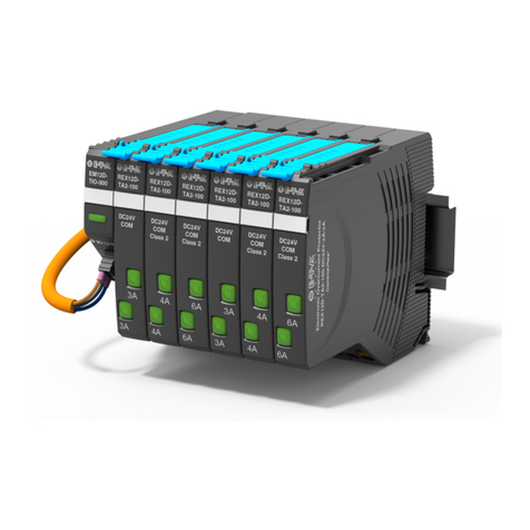
E-T-A EM12D-TMB Series User manual

Installationsanleitung / Installation Manual
Intelligentes Einspeisemodul EM12D-TMB-xxx
Intelligent Supply Module EM12D-TMB-xxx

LINE-Anschluss / GND-Anschluss
Nennspannung: DC 24 V (18 ... 30 V)
Tragschiene erden (PE/FE)
Summenstrom: max. = 40 A
LINE-Anschluss 10 mm² Push-in-Klemme
0V-Anschluss 2,5 mm² Push-in-Klemme
X81/ X82 COM-Schnittstelle zum Modbus Server
Typ: Stecker 3-polig
Bei der Verdrahtung und dem Anschluss sind die Installations- und
Verdrahtungsvorschriften der Modbus-Spezifikation ist einzuhalten.
Anschluss 1: Data A
Anschluss 2: Data B
Anschluss 3: GND
LINE terminal / GND terminal
Voltage rating: DC 24 V (18 ... 30 V)
ground symmetrical rail (PE/FE)
Total current: max. = 40 A
LINE terminal 10 mm² push-in terminal
0V terminal 2.5 mm² push-in terminal
X81 / X82 COM interface to Modbus server
Type: connector 3-pin
When wiring and connecting the installation and wiring regulations of the
Modbus implementations guide have to be observed.
connector 1: Data A
connector 2: Data B
connector 3: GND
Modbus
RTU
A
B
G
N
D
X81
X82
0V
LINE +1
A
B
G
N
D
Entrance Module
EM12D-TMB-000-DC24V-40A
Modbus-RTU
LED CE/CM
Ansicht X
Modbus RTU
X81/ -X82 COM
Schnittstelle RS485
Kommunikation A
Kommunikation B
Kommunikation GND
0 V DC
LINE+ DC
Stecker
3-polig
Ansicht X
GERMANY
x10 x1 Baudrate
Bus-Address parity
E-T-A
D-90518 Altdorf
Made in Germany
xxxx · xxx x
Fertigungscode
Device ID des Gerätes
Revisionsstand der Firmware
12,4
91,5
80 7,5
98
Schnappsockel für
Trageschiene
EN 60715-35x7,5
Modbus
RTU
A
B
G
N
D
X81
X82
0V
LINE +1
A
B
G
N
D
Entrance Module
EM12D-TMB-000-DC24V-40A
Modbus-RTU
LED CE/CM
view X
Modbus RTU
X81/ -X82 COM
interface RS485
communication A
communication B
communication GND
0 V DC
LINE+ DC
3-pole
plus
view X
GERMANY
x10 x1 Baudrate
Bus-Address parity
E-T-A
D-90518 Altdorf
Made in Germany
xxxx · xxx x
date code
Device ID
revision status of firmware
12,4
91,5
80 7,5
98
snap-on socket for
rail EN 60715-35x7.5
1. Safety instructions
Important: Please read carefully before use. Keep for future
reference.
Caution:
The product must only be used for the indicated voltage
and frequency range E-T-A is unable to accept
responsibility for customer or third party liability, warranty claims
or damage caused by incorrect installation or improper
handling in disregard of the technical data.
For use up to overvoltage category III; pollution degree 2;
degree of protection IP 20 in the operating area.
Observe max. input / output current.
The intelligent supply module is a built-in unit. Modifications of the
device are not allowed.
Warning:
Installation and operation must only be carried out by
qualified personnel. The relevant national standards
have to be observed. Warning: Danger of electric
shock and fire hazard. Check for damages before
installation. Defective devices must not be used.
2. LED indication and connection
1. Sicherheitshinweis
Wichtig: Vor Gebrauch sorgfältig lesen. Für späteres Nachschla-
gen aufbewahren
Achtung:
Geräte sind ausschließlich für den angegeben Spannungs-
und Frequenzbereich vorgesehen. E-T-A übernimmt gegen-
über dem Kunden oder Dritten keine Haftung, Gewährleistung
oder Garantie für Mängel oder Schäden, die durch fehlerhaf-
ten Einbau oder unsachgemäße Handhabung unter Nichtbe-
achtung der technischen Daten verursacht wurde.
Zur Verwendung bis Überspannungskategorie III; Verschmutzungs-
grad 2; Schutzart IP 20 im Betätigungsbereich
Max. Eingangs- / Ausgangstrom beachten.
Das intelligente Einspeisemodul ist ein Einbaugerät. Keine Modifika-
tionen am Gerät zulässig.
Warnung:
Die Installation und Inbetriebnahme darf nur von entspre-
chend qualifiziertem Fachpersonal durchgeführt werden. Es
sind dabei die landesspezifischen Vorschriften einzuhalten.
Warnung: Gefahr durch elektrischen Schlag und Brandge-
fahr. Vor der Installation auf Beschädigungen prüfen. Defekte
Geräte dürfen nicht verwendet werden.
2. Anzeige- und Anschlusselemente
!
!
!
!

LED CE/CM
Die Leuchtdiode CE/CM zeigt den Status der Kommunikationseinheit an.
Funktionszustand LED Modbus Kommuni-
kation EM12D-TMB
Unabhängiger
Betrieb grün blinkend nicht vorhanden
Fehlerfreier Betrieb grün vorhanden
Kritischer Fehler
wurde erkannt. rot nicht vorhanden
Unkritischer Fehler
wurde erkannt gelb vorhanden
Unkritischer Fehler
wurde erkannt gelb blinkend nicht vorhanden
Bootloader-Modus
aktiv rot blinkend nicht vorhanden
3. Montieren
Das Gerät auf Hutscheine montieren (Einbaulage horizontal).
4. Anschließen
Leitungen entsprechend dem Eingangs- und Ausgangsstrom dimensi-
onieren. Schließen Sie zwingend den Neutralleiter an, um die Eigenver-
sorgung der Elektronik sicher zu stellen.
4.1 Push-in-Klemme
Den Leiter direkt in die Klemme stecken. Zum Lösen der Verbindung
Klemmenbetätiger (orange) mit einem geeigneten Werkzeug drücken.
Anschluss Querschnitt Abisolierlänge
LINE+ (1) 0,5 mm²…10 mm² 18 mm
0 V (0 V) 0,14 mm²…2,5 mm² 8 mm...10 mm
X81 COM (A, B ,GND
0,25 mm²…0,5 mm² 6 mm
X82 COM (A, B ,GND) 0,25 mm²…0,5 mm² 6 mm
LED CE/CM
The LED CE/CM shows the status of the communication unit.
operating
condition LED Modbus communi-
cation EM12D-TMB
independent
operation blinking green not available
faultless operation green available
critical failure
detected red not available
uncritical failure
detected yellow available
uncritical failure
detected blinking yellow not available
bootloader mode
active blinking red not available
3. Mounting
Mount the device on the symmetrical rail (mounting position: horizontal).
4. Connection
Select cable size in accordance with the input and output
current. Connection of the neutral conductor is imperative to
ensure self-supply of the electronic circuitry.
4.1 Push-in terminals
Plug in the conductor directly into the terminal.
For release push the release button (orange) with a suitable tool.
Connection Cross section Wire stripping
length
LINE+ (1) 0.5 mm²…10 mm² 18 mm
0 V (0 V) 0.14 mm²…2.5 mm² 8 mm...10 mm
X81 COM (L+, C/Q, L-)
0.25 mm²…0.5 mm² 6 mm
X82 COM (A, B ,GND) 0.25 mm²…0.5 mm² 6 mm
Hinweis: Ausführliche Handbücher, Produktdatenblätter und Soft-
ware- tools sind auf der E-T-A Homepage zum Download bereitge-
stellt. Stellen Sie sicher, dass Sie immer mit den aktuellen Doku-
menten arbeiten.
Note: Detailed user manuals, data sheets and software tools are
available on the E-T-A home- page for download. Please make sure
to always use the most recent documents.

Installationsanleitung / Installation Manual EM12D-TMB (D,E)
Bestell-Nr. / Ref. number Y31274701 - Index: -
Ausgabe / Issue: 02/2018 / Alle Rechte vorbehalten / All rights reserved
E-T-A Elektrotechnische Apparate GmbH
Industriestraße 2-8 .90518 ALTDORF
GERMANY
Tel. 09187 10-0 .Fax 09187 10-397
http://www.e-t-a.de/QR1033/
Other manuals for EM12D-TMB Series
1
Other E-T-A Control Unit manuals
Popular Control Unit manuals by other brands
Baker Hughes
Baker Hughes Mooney Flowgrid Slam Shut instruction manual
GEM
GEM 768 operating instructions

Rokonet
Rokonet ProSYS ACM installation guide

OUMAN
OUMAN OUFLEX M BA user manual

Boyertown Furnace
Boyertown Furnace PurePro Energy Manager PRO 6000Z installation instructions

Jolly Mec
Jolly Mec Control Display user manual
