User's Guide
SLVU720A–June 2012–Revised November 2012
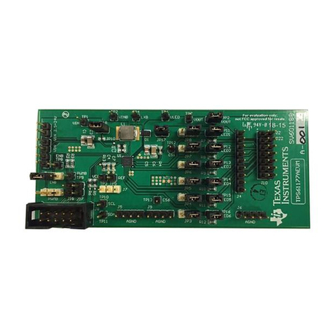
TPS650380EVM-054
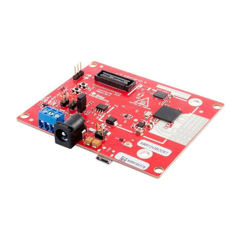
This user’s guide describes the characteristics, operation, and use of the Texas Instruments
TPS650380EVM-054 (PWR054-001) evaluation module (EVM). This EVM is designed to help the user
evaluate and test the operation and functionality of the TPS650380. The EVM converts a 2.5-V to 5.5-V
input voltage to 3 regulated output voltages that deliver 5 A, 2 A, and 1.8 A. The 5-A output operates 3
phases, the 2-A output operates 2 phases, and the 1.8-A output operates a single phase. The output
voltages are programmable via the I2C™ interfaces in 10-mV steps between 0.5 V and 1.77 V. This
user’s guide includes setup instructions for the hardware, printed-circuit board layouts for the EVM, a
schematic diagram, a bill of materials, and test results for the EVM.
Contents
1 Introduction .................................................................................................................. 2
2 Setup ......................................................................................................................... 3
3 Software Setup and Operation ............................................................................................ 8
4 Test Results ................................................................................................................ 11
5 Board Layout ............................................................................................................... 18
6 Schematic and Bill of Materials .......................................................................................... 24
List of Figures
1 TPS650380 Software Main Panel ........................................................................................ 8
2 Efficiency vs. Input Voltage (DCDC_A = DCDC_B = DCDC_C = 0.96 V, IOUTA = 3.4 A, IOUTB = 1.85 A, IOUTC
= 0.9 A) ..................................................................................................................... 11
3 Efficiency of DCDC_A vs. Output Current (VIN = 3.6 V).............................................................. 11
4 Efficiency of DCDC_B vs. Output Current (VIN = 3.6 V).............................................................. 12
5 Efficiency of DCDC_C vs. Output Current (VIN = 3.6 V).............................................................. 12
6 Load Regulation (VIN = 3.6 V, DCDC_A = DCDC_B = DCDC_C = 0.96 V) ....................................... 13
7 Line Regulation (DCDC_A = DCDC_B = DCDC_C = 0.96 V, IOUTA = 3.4 A, IOUTB = 1.85 A, IOUTC = 0.9 A)..... 13
8 Start-up (VIN = 3.6 V, DCDC_A = DCDC_B = DCDC_C = 0.96 V, IOUTA = IOUTB = IOUTC = 0 A) ................... 14
9 Shutdown (VIN = 3.6 V, DCDC_A = DCDC_B = DCDC_C = 0.96 V, IOUTA = IOUTB = IOUTC = 0 A, Active
Output Capacitor Discharge Enabled).................................................................................. 14
10 Shutdown (VIN = 3.6 V, DCDC_A = DCDC_B = DCDC_C = 0.96 V, IOUTA = IOUTB = IOUTC = 0 A, Active
Output Capacitor Discharge Enabled).................................................................................. 15
11 Output Voltage Ripple Measured Across C6 (VIN = 3.6 V, DCDC_A = 0.96 V, DCDC_B = DCDC_C =
disabled, IOUTA = 5 A) ...................................................................................................... 15
12 Input Voltage Ripple Measured Across C13 (VIN = 3.6 V, DCDC_A = 0.96 V, DCDC_B = DCDC_C =
Disabled, IOUTA = 5 A)...................................................................................................... 16
13 Load Transient Response (VIN = 3.6 V, DCDC_A = 0.96 V, DCDC_B = DCDC_C = Disabled, IOUTA = 3 A
to 5 A step)................................................................................................................. 16
14 Loop Response (VIN = 3.6 V, DCDC_A = 0.96 V, DCDC_B = DCDC_C = Disabled, IOUTA = 5 A) .............. 17
15 Thermal Performance (VIN = 3.6 V, DCDC_A = DCDC_B = DCDC_C = 0.96 V, IOUTA = 3.4 A, IOUTB = 1.85
A, IOUTC = 0.9 A) ............................................................................................................ 17
16 Assembly Layer............................................................................................................ 18
17 Top Silk Layer.............................................................................................................. 19
18 Top Layer................................................................................................................... 20
I2C is a trademark of NXP B.V Corporation.
VeriSign is a trademark of VeriSign, Inc.
All other trademarks are the property of their respective owners.
1
SLVU720A–June 2012–Revised November 2012 TPS650380EVM-054
Submit Documentation Feedback Copyright © 2012, Texas Instruments Incorporated

