www.rosscontrols.com 3
5/2 RSe Series Double Valves for Safe Return Dual Pressure Integration Guide
Introduction
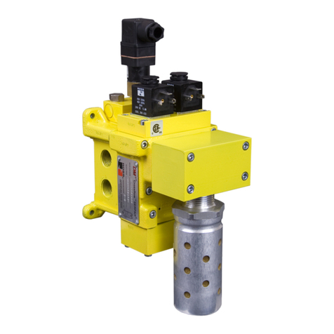
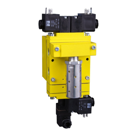
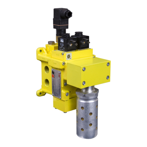
ROSS CONTROLS offers a variety of safety valves for use in various safety functions such as safe exhaust, safe return, and safe
load holding/stop. This document focuses specifically on ROSS CONTROLS’ 5/2 RSe Series valves that are used for dual pressure
safe cylinder return functions and utilize magnetic proximity sensors (PNP) to provide feedback to a safety control system for external
monitoring.
The intent of this document is to provide guidance on how to connect, operate, and monitor the 5/2 RSe when used in Safe Return Dual
Pressure applications. Using the 5/2 RSe as a Safe Return Dual Pressure control valve requires the valve to be converted to external pilot
supply and the normal exhaust ports (3 and 5) will be used for pressure supply. Port 1 will be used as the exhaust port. The RSe valve will
then be setup so as to supply a different pressure to extend than to retract. A test procedure is also provided for verification and validation
of the user’s external safety control monitoring system.
Pulse Testing
In dual channel safety circuits, pulse testing is a method utilized to detect fault conditions that, otherwise, may be undetected. Pulse testing
of the solenoids is required in dual channel circuits in order to reach Performance Level e (PL e). However, pulse testing of the feedback
sensors is not required. Pulse testing of the solenoids will not affect the performance of the ROSS 5/2 RSe valve.
There are two methods of pulse testing outputs. The most common method is to use the native pulse testing instruction embedded by
the manufacturer in Safety PLCs and Safety Relays. The other method is to use custom programming code generated by the user. We
recommend the use of native pulse testing instructions of the respective manufacturers’ Safety PLCs or Safety Relays because these
instructions are fixed and cannot be tampered with. These instructions typically have a pulse period (cycle) of 400 ms to 600 ms and a
pulse width of 0.4 ms to 0.8 ms. Pulse testing the outputs to the solenoids on the RSe valve at this frequency and duration does not affect
the performance of the valve but does provide a method to monitor for the occurrence of wiring faults in the output portion of the safety
circuit controlling the valve solenoids.
Considerations for Safe Distance Calculations
In a dual pressure safe cylinder return application, the critical point of operation is that the valve, even if faulted, should reverse the
condition of the work ports as quickly as possible. This means that when the valve is de-actuated or a fault occurs port 4 should begin
to be pressurized and port 2 should begin to be exhausted as quickly as possible.
Increases in the time for this reversal to occur would be the worst-case scenario in this type of application. It would be expected that a
difference in time to reverse these conditions would occur when the valve is faulted. Data indicates that of the three sizes of the 5/2 RSe
valves there is an increase of at most 10 ms. This is only parts movement time based on the ISO 12238 standard for measuring valve
response time.
There is also a corresponding reduction in Cv in both supplying port 4 and exhausting port 2 which will generate a net reduction in
cylinder return speed. It is important to note that a precursor for safe cylinder return applications is that there should be no hazard in the
reverse direction. Otherwise, a stop type solution (load holding) would have been required. Therefore, a slower retract may be desirable.
Safe Distance calculations should be validated by testing.
Simplified Schematic Valve Schematic
1
2
4
35
EPS
2
4
5 1 3
2
2
1
3
4
51 3
2
2
1
3
4
35
14 14
1
EPS
Cv Values De-actuation Time
(time in ms from energized to valve in de-actuated position)
Port Size Normal Faulted
1-2 4-5 1-2 4-5 Valve Basic Size Normal Response Faulted Response
1/8 0.82 0.87 0.64 0.63 1/8 50 51
1/4 1.09 1.14 0.83 0.69 1/4 86 95
1/2 3.83 3.48 1.54 1.39 1/2 209 227
