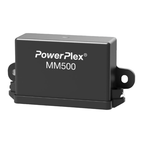
E-T-A PowerPlex CM500 User manual

Compact Module CM500
Installation and Operating Instructions

2
User Manual PowerPlex®
Issue: M_PP-M-CM500-E –Index: -
Date of publication: October 2020
Reference document: -
Editor:
E-T-A Elektrotechnische Apparate GmbH
Industriestraße 2-8
90518 Altdorf
GERMANY
Phone: +49 (0) 91 87 / 10-0
Facsimile: +49 (0) 91 87 / 10-397
Web: ww.e-t-a.com
Copyright ©2020 E-T-A GmbH
The contents of this document is the property of E-T-A GmbH. No part of this publication must in any we be
reproduced or distributed without prior written consent of E-T-A GmbH. Any person acting illegally with regard to
this publication can be prosecuted.
Limitation of liability
Although all provisions were taken when creating this document, the editor does not accept any responsibility for
errors or omissions or for damages caused by using the information contained in this document. The information
contained in this document may be revised at any time without pre-advise.
Brands
All references to software and hardware in this document are generally protected by brands or patents.
© E-T-A GmbH 2020. All rights reserved.

3
About this manual
This manual describes start-up of the PowerPlex®Compact Module (PP-M-CM500) in connection with compatible
PowerPlex®components. We assume that all PowerPlex®compatible components and devices were installed
correctly. The instruction is meant to be used by all professional electricians who want to integrate this control
panel into an E-T-A PowerPlex®system. The PowerPlex®keypads allow easy and intuitive operation and
monitoring of the PowerPlex®installations.
Besides this document further information on the E-T-A PowerPlex®can be found on E-T-A’s Website.
All manuals contain important instructions for connection and safe operation of the PowerPlex®devices. Safety
instructions have to be observed. All users have to be informed about all safety instructions. The documents have
to be accessible for the user.

4
Qualified personnel
The system must only be installed, connected and configured in connection with this document.
Installation and operation of the device/system must only be carried out by qualified personnel. With
regard to the safety instructions of this documentation, qualified persons are persons authorised to
operate devices, systems and circuits according to the standards and rules of safety engineering.
Safety instructions
Please follow the installation and configuration instructions given in this document carefully. Failure to
comply may lead to serious damages of the product or the system. E-T-A is unable to accept
responsibility for customer or third-party liability, warranty claims or damage caused by incorrect
installation or improper handling in disregard of the Installation and Operating Instructions.

5
Content
About this manual 3
Content 5
List of pictures 6
List of tables 6
Symbols 6
1. Introduction 7
2. System components: Overview 8
3. PowerPlex®system: General 11
3.1. PowerPlex®Modules 11
3.2. PowerPlex®CAN Bus 11
3.3. Put down the serial number 13
3.4. The CAN bus address 13
4. General: PowerPlex®Compact Module CM500 13
4.1. Technical data 14
4.2. Scope of delivery 15
4.3. Inputs, outputs and interfaces 15
5. Mounting 17
5.1. Installation check list 17
5.2.
Recommended installation site 17
5.3. General notes on wiring 18
5.4.
Required installation dimensions - mounting cut-out 18
5.5. Dimensions and space requirements 19
5.6. Mounting of the device 19
6. Connection to power supply 21
7. Integration of the device in the CAN bus network 21
8. PowerPlex®Configuration Software 23
8.1. Computer Requirements 23
8.2. Software installation 23
9. CAN/USB converter and driver 24
10.Important information and safety instructions 24
Notes 25

6
List of pictures
Fig. 1: Exemplary system design of a recreational vehicle ......................................................................................8
Fig. 2: Exemplary system design –Boat..................................................................................................................8
Fig. 3: Overview of PowerPlex® components..........................................................................................................9
Fig. 4: Two PowerPlex® modules connected via CAN bus cable..........................................................................12
Fig. 5: Various PowerPlex® modules connected via serial CAN bus topology......................................................12
Fig. 6: PowerPlex® Compact Module CM500........................................................................................................13
Fig. 7: Pin assignment of the PowerPlex® Compact Module.................................................................................15
Fig. 8: Dimensions of the PowerPlex® Compact Module.......................................................................................19
Fig. 9: Installation dimensions of the PowerPlex® Compact Module.....................................................................19
Fig. 10: Connection of the PowerPlex® components in the CAN bus system.......................................................21
Fig. 11: CAN/USB converter (example: Peak) .......................................................................................................24
List of tables
Table 1: Symbols used 6
Table 2: Additional accessories 10
Table 3: Different PowerPlex® Modules 11
Table 4: Selection of technical data 14
Tabel 5: Inputs, outputs and interfaces of the PowerPlex® Compact Module 16
Table 6: Installation check list 17
Table 7: General requirement of the installation site 17
Table 8: General notes on wiring 18
Table 9: Mounting of the device 20
Table 10: Pin assignment on the 2-pole connector (X1) 20
Table 11: Pin assignment on the 10-pole connector (X2) 20
Tabel 12: Pin assignment on the 22-pole connector (X3) 20
Table 13: Major properties of the CAN bus cable to be used 22
Table 14: Requirements of the configuration PC 23
Table 15: Important information 24
Symbols
The following conventions and symbols will accompany you throughout the entire manual. They are defined as
follows:
Warning
You are in a situation which might cause injury. Before working with one of the devices you have to be
aware of the risks of electrical circuitries and you ought to be familiar with standard procedures of
accident prevention.
Caution
There is a risk in this situation to do something which might cause damage of the devices or data loss.
Information
Here you receive information which might be particularly useful for the application.
Table 1: Symbols used

7
1. Introduction
You chose PowerPlex®, a comprehensive, future-oriented on-board system which combines safety, user
convenience and reliability. It is a decentralised power distribution and control system, regulating, controlling and
monitoring various loads, switches and sensors and connecting them via CAN. All PowerPlex®modules ensure
reliable control and monitoring of the electrical installations on board, either alone or in combination with other
PowerPlex®components. Besides the protection against overcurrent they allow readout of data of the connected
level sensors and temperature sensors as well as of shunts.
By means of the PowerPlex®configuration software, the application-specific logics for power distribution, power
control and power monitoring will be defined, stored or adjusted. Communication takes place via the PowerPlex®
CAN, based on SAE J1939.
Thanks to its system properties PowerPlex®is the perfect solution for smart electrical networks on boats and in
vehicles. Typical applications include:
•Buses, special vehicles, mobile homes etc.
•Watercraft, e.g. leisure boats, workboats
Benefits for the OEM
The E-T-A PowerPlex®system allows switching and controlling of various loads, timer functions, real load status
indication, overcurrent protection and wire break detection. Each function can be configured separately to meet
the requirements of the loads.
Based on the CAN communication the PowerPlex®system allows to make individual wiring between load and
control unit a thing of the past. The transmission of switch commands and status information is based on the peer-
to-peer CAN bus communication. A direct cable connection between the actuator, e.g. a light switch, and the load,
e.g. a lamp, is no longer required. The obvious advantages for the OEM include the reduced wiring and production
costs as well as a convenient system setup by means of a Windows based configuration software. All control
functions of the system are freely configurable with regard to complexity and size of the system. Change or system
extension at a later date are also extremely easy.
PowerPlex®Scope of operation –PowerPlex®takes over the following tasks:
•Distributes the DC 12 V or DC 24 V power supply to all spots of the boat where loads are installed, such
as lighting and heating control, bilge and water pumps, windscreen wiper motors etc.
•Collects all status information of all sensors and actuators everywhere in the vehicle, such temperature
and tank level measuring points, ON/OFF status signals of the actuators.
•Switches devices and equipment ON and OFF, according to selectable, pre-set scenarios, at the touch
of a button.
•Monitors devices and equipment regarding their out-of-range conditions, indicates possible failures and
responds by reversing the pertinent control unit, as e.g. switching on a pump, if the water tank level falls
below a certain limit.
•Protects devices and equipment against hazardous overcurrent and short circuit by isolating the faulty
load from the system and failure indication to the system.
•Offers back-up protection and switching in the improbable case of a PowerPlex®system or component
failures.

8
2. System components: Overview
The PowerPlex®system of E-T-A is a comprehensive on-board system combining safety, convenience and
reliability. PowerPlex®allows individual and flexible concepts of switching the illumination, acoustic and special
signals and lots more. It automatically switches loads and immediately indicates undesired conditions of the
devices or of the entire electrical installation. Thus it is ensured, that everything works precisely - which is
reassuring, as the loads often are not in plain sight. E-T-A PowerPlex®is a decentralised power distribution system
with electronic protection –clearly reflecting trends of the future.
Fig. 1 and Fig. 2 show typically PowerPlex®solutions with an application-specific number of PowerPlex®
components - modules and control units –installed at various positions.
Fig. 1: Exemplary system design of a recreational vehicle
Fig. 2: Exemplary system design –Boat

9
PowerPlex®communication is based on the CAN bus principle by means of “nodes”, which communicate with
each other via a serial 2-wire connection. Hence the key components of a PowerPlex®system are these nodes
distributed over the vehicle or boat. The overall PowerPlex®term for these interconnected nodes is “module".
Various hardware components are required for installation and start-up of a PowerPlex®system:
Please check the delivered components upon receipt about completeness. You require the following hardware
components for installation and start-up of a PowerPlex®system:
•one or more PowerPlex® modules (e.g. DC Power Module, DC Mini Module) that meet application-specific
requirements
•USB-CAN converters (cable and driver) for transferring the configuration
•USB cables for the USB service interface for transferring application-specific user interfaces onto
PowerPlex®Touch Panels.
In addition, you require a CAN bus cable for connecting the PowerPlex®components to the bus. Many
manufacturers offer standard cables for this purpose. For more information on the required cable properties please
see chapter 7 of the manual.
PowerPlex®reliably and precisely connects, regulates, controls and monitors electrical loads, switches and
sensors via CAN. It controls status indications, operating conditions and execution of commands. Perfectly
matched software and hardware components offer a comprehensive total solution with maximum potential of
individualisation.
Each module protects the loads and cable harnesses against overcurrent. In addition the modules collect data of
level sensors and temperature sensors as well as of shunts. Usually a PowerPlex®system consists of several
modules of different kinds. The selection depends on the size of the electrical system to be monitored and
controlled as well as of the current ratings of the loads.
Use our PowerPlex®Configuration Software to “programme” various control configurations. As requested, you
can store them on the computer and load them into various PowerPlex®control systems. As soon as a
PowerPlex®configuration has been completed, it will be transferred to the PowerPlex®modules (”nodes”) via the
CAN bus interface. Via this CAN bus interface you also connect the PowerPlex®software for testing, analysing
and debugging purposes of the PowerPlex®installation.
Fig. 3 shows the entire PowerPlex®product range to enable you to design your own PowerPlex®system solution:
Fig. 3: Overview of PowerPlex® components

10
More components required for setting up a PowerPlex®system are shown in .
Accessories
Description
PowerPlex®Suite
Configuration software for defining addresses, characteristics and functions of the
PowerPlex®modules, assignment of the inputs and outputs to the modules and
execution of system tests and analyses.
CAN-USB converter plus driver
CAN-USB adapter for connecting the CAN bus hardware to the USB interface of the
computer with the PowerPlex®configuration software and/or to the USB interface of
a touch panel which could be connected to the PowerPlex®.
Terminating resistors
Two 120 Ω resistors terminate the CAN bus network, one on each end of the CAN
bus.
CAN bus cable
A trunk CAN bus cable in pairs with two conductors (CAN-H and CAN-L) and the
shield (SHLD) connect two PowerPlex®modules with each other.
Power supply
12 V DC or 24 V DC battery voltage supply
Line protection
Protection of the L (+) connection from a PowerPlex®module to the battery or to the
CAN bus.
Recommendation: Thermal-magnetic E-T-A 8345 circuit breaker type.
Table 2: Additional accessories

11
3. PowerPlex®system: General
3.1.PowerPlex®Modules
PowerPlex®modules are the key components of a PowerPlex®network. According to the CAN bus terminology
they are the “nodes” of the network and form the points of switching, transmission and control.
PowerPlex®for DC system include high-end power semi-conductors with integral protective elements for switching
and protection of electrical loads. The modules are free of mechanical components and thus insusceptible to wear
and shock and vibration resistant.
E-T-A offers various PowerPlex®modules for DC 12 V and DC 24 V systems. gives an example of the difference
between two modules.
DC Modules
Compact Module
CM500
Power Module
PM500
Voltage ratings
DC 12 V/24 V
DC 12 V/24 V
max. total current
60 A per module
102 A per module
Inputs
digital
8, configurable
8
analog
4
Outputs
4 (max. 3 A, dimmable)
10 (max. 10 A, dimmable)
4 (max. 1 A, dimmable)
6 (max. 8 A, FLPC)
2 (max. 25 A, FLPC)
Degree of protection
IP22
IP22
Part number
PP-M-CM500-000-0-Z-00
PP-M-PM500-000-0-0-00
Table 3: Different PowerPlex® Modules
3.2.PowerPlex®CAN Bus
A PowerPlex® network can embrace up to 30 different PowerPlex® modules. The smallest PowerPlex®system
would consist of two modules communicating via the CAN bus cable (see Fig. 4).
The loads controlled by the modules - in this case a light and bilge pump - are normally installed at some place in
the vehicle which may not be necessarily close to the input signal. The decentralised control structure of
PowerPlex®allows monitoring and switching of the devices anywhere on the vehicle or boat from any chosen
installation site.
A level sensor monitors the bilge and supplies the analog information on module 1. From there the information is
transferred to module 2 via the CAN bus. As soon as the measured analog input value (i.e. the “pumping level”)
has exceeded a pre-set limit value , module 2 will send a switch command to the load (i.e. the “bilge pump”) so
as to switch on the pump and to reduce the water level of the bilge back to an acceptable level. The status
information of the bilge pump will be sent back to module 1 to switch on the display “bilge pump running”.
In addition, module 2 monitors the position of a light switch –ON or OFF –at one of the digital inputs and sends
the switching signal to module 1, which switches the light ON or OFF depending on the switching status.

12
Fig. 4: Two PowerPlex® modules connected via CAN bus cable
An example demonstrates the principle of using the sensor and switching signal information at the module inputs
as well as the sending, switching or the display of commands to the outputs of the same or a different module.
A typical PowerPlex®control system will of course connect a much higher number of modules and their inputs
and outputs which will be distributed over the entire vehicle. Fig. 5 shows the electrical connection of several
PowerPlex®modules in a serial CAN bus topology. Each module must be connected to the DC voltage supply
and the CAN bus.
Fig. 5: Various PowerPlex® modules connected via serial CAN bus topology
Note
The first and last Modules of the CAN bus topology must be connected with a 120 Ω terminating resistor
between the CAN high and CAN low signals. This helps avoiding interferences on the bus.

13
3.3.Put down the serial number
Each PowerPlex®component has a unique serial number. Before mounting the PowerPlex®modules, we
recommend to prepare a list. This list should include: PowerPlex®component (module type), pertinent serial
number and installation area.
You find the serial number of the PowerPlex®Compact Module on the label attached to the housing. The serial
number consists of 7 letters and numbers. It is used as an identification for new, not yet projected modules which
have the CAN bus address “0” for a start. The serial numbers are required for system set-up. By means of the
PowerPlex®configuration software the pertinent CAN bus addresses will be assigned.
Note
Please note the 7-digit serial number of each PowerPlex®component. It is required for the subsequent
system configuration with the PowerPlex®configuration software.
Later, when you start configuring the modules and when you define their roles in the CAN network, the assignment
between serial number, CAN bus address and installation area must be made.
The use of CAN bus address labels helps keeping an overview for module identification, above all in the event of
comprehensive projects.
3.4.The CAN bus address
Any PowerPlex®component within a PowerPlex®network has its own, unique CAN bus address in a range of 1
to 30 for a clear identification. Assignment of the CAN bus addresses is during the system set-up by means of the
PowerPlex®Configuration Software (cf. PowerPlex®Manual Volume 3: System set-up and configuration).
We recommend to mark the modules in the PowerPlex®system with the corresponding CAN bus addresses so
as to be able to keep track.
4. General: PowerPlex®Compact Module CM500
Growing demands regarding safety and convenience lead to the installation of more and more electrical loads in
vehicles and boats. The PowerPlex® Compact Module (Fig. 6) is a multifunctional module that perfectly
complements the PowerPlex® product range. Like all the other PowerPlex®components it meets the special
requirements of marine and recreational vehicles applications.
It offers eight multifunctional inputs, which can be used for measuring current, voltage, temperature and/or liquid
levels, as well as 14 load outputs.
Fig. 6: PowerPlex® Compact Module CM500

14
4.1.Technical data
The technical information of the PowerPlex®Compact Module are summarised in Table 4.
Technical Data
Rated voltage
DC 12 V/24 V
Operating voltage
9 ... 32 V DC
Current consumption
typically 63 mA at 12 V
typically 44 mA at 24 V
Max. total current
60 A per module
Degree of protection
IP22 when mounted vertically with terminals pointing downwards
Operating temperature range
-30 … +70°C (-22 … 158 °F)
with derating above +50 °C (+122 °F)
Storage temperature range
-30 … +85°C (-22 … 185 °F)
mass
approx. 410 g
Interfaces:
CAN I*
PowerPlex® CAN, 250 kbit/s, galvanically isolated
CAN II*
CAN II galvanically isolated, protocol upon request
*) The CAN-terminals at each end of a CAN bus require a termination by a 120 Ω resistor.
LIN
LIN bus interface (CI-BUS) upon request
Inputs:
8 multifunctional inputs, configurable as
I1
I2
I3
I4
I5
I6
I7
I8
digital input:
0 … 8 kΩ: ON; > 10 kΩ OFF;
plus or minus switching
⚫
⚫
⚫
⚫
⚫
⚫
⚫
⚫
analog inputs:
a)
voltage monitoring:
0 … 32 V, Rin: 60 kΩ;
resolution: 10 Bit
⚫
⚫
⚫
⚫
⚫
⚫
⚫
⚫
b)
battery monitoring:
± 60 mV; battery current
measurement with external shunt
(I3 & I4)
+
-
c)
resistance measurement:
0 ... 750 Ω; for tank levels and
temperature
⚫
⚫
⚫
⚫
⚫
⚫
⚫
⚫
d)
frequency measurement:
0 … 10 kHz (I1 & I2)
⚫
⚫
Outputs
10 outputs with 10 A max. continuous current
load output
Power MOSFET, high side switching (HSS)
max. current rating
10 A, adjustable in 1 A steps
typical voltage drop UON at
rated current (25 °C):
60 mV
tripping range at overload
1.01 … 1.30 x IN
motor function:
Switching of 2 H-bridges possible
(X2: O1 & O2, X2: O6 & O7)
high current function
20 A outputs via parallel connection of two load outputs (X2: O1 … O10)
dimming function:
all outputs are high-frequency dimmable, frequency adjustable
4 outputs with 3 A max. continuous current
load output
Power MOSFET, high side switching (HSS)
max. current rating
3 A, adjustable in 1 A steps
typical voltage drop UON at
rated current (25 °C):
75 mV
tripping range at overload
1.01 … 1.30 x IN
dimmer function:
all outputs are high-frequency dimmable, frequency adjustable
Approvals
approval authority: KBA
Standard: ECE regulation No 10 (E1)
Rated voltage: DC 12/24 V
Part number
PP-M-CM500-000-0-Z-00
Table 4: Selection of technical data
*) For further information please see the relevant data sheet.

15
4.2.Scope of delivery
Standard scope of delivery of the PowerPlex®Compact Module is without accessories.
For completion we recommend the following accessories:
•USB/CAN Converter:
XPP-USBC0
XPP-USBC1 (opto-decoupled)
•Connection package:
XPP-CP-130
(contains a 2-, 10- and 22-pole connector, 10 x crimp contacts 14-16 AWG and
22 x crimp contacts 16 AWG))
•Temperature sensor
XPP-TS500R-HB
(-30 … +100 °C (-22 … +212 °F))
XPP-TS500R-PH
(-30 … +100 °C (-22 … +212 °F))
4.3.Inputs, outputs and interfaces
Fig. 7 shows an overview of the terminals and interfaces of the PowerPlex®Compact Module.
Fig. 7: Pin assignment of the PowerPlex® Compact Module
Explanation:
•Inputs (X3: I1 - I8) are multifunctional inputs which can be configured as a digital or analogue input.
•GNDIare ground terminals only for the multifunctional inputs (X3: I1 - I8). The outputs must be connected
to external ground GNDO.
•Outputs are dimmable outputs
owith max. 10 A continuous current, (X2:O1 - O10)
owith max. 3 A continuous current, (X3: O1 - O4)
•Outputs (X2: O1 & O2; O6 & O7) can be used for switching H-bridges (motor function).
•Ubatt+ and Ubatt- are for the connection of the power supply
•CAN-H, CAN-L, SHLD are the interfaces to the CAN buses (CAN I: PowerPlex® CAN; CAN II: other CAN
bus)

16
Input/ output/
interface
what is connected
connection
cable connection
protection & status
indication/comments
X1: 2-pole connection
voltage supply
DC 12 V/24 V
(DC 9 V … 32 V)
UBatt +
Ubatt ‒
BUZ 10.16IT/02/*
battery connection
X2: 10-pole connection
power output
10 A
loads
with max. 10 A
O1 - O8
crimp connector, 16
AWG
short-circuit and over-current
protection: Current limitation and
electronic safety shutdown; motor
function: two H-bridges (O1&O2,
O6&O7); high current function: 20
A outputs via parallel connection of
two load outputs; dimming function
with adjustable frequency
X3: 22-pole connection
PowerPlex® CAN
CAN bus cable
6-pole Molex
connector
crimp connector, 16
AWG
based on SAE J1939, galvanically
isolated
CAN II
CAN bus cable
input: digital
switch, momentary switch,
...
I1 - I8
crimp connector, 16
AWG
control inputs, switching to ground
input: analogue
battery, charger, sensor, ...
I1 - I8
crimp connector, 16
AWG
voltage measurement
external shunt
I3(+) & I4(-)
crimp connector, 16
AWG
battery current measurement
± 60 mV,
note: when monitoring the battery,
it must be ensured that
PLUS/MINUS are correctly
connected.
tank sensor
I1 - I8
crimp connector, 16
AWG
monitoring of tank levels
temperature sensor:
I1 - I8
crimp connector, 16
AWG
temperature monitoring
ground for
multifunctional
inputs
GNDI
GNDI
crimp connector, 16
AWG
caution: ground of load outputs
GNDOmust be connected
externally!
power output
3 A
loads
with max. 3 A
O1 - O4
crimp connector, 16
AWG
short-circuit and over-current
protection: Current limitation and
electronic safety shutdown;
dimming function with adjustable
frequency
LIN interface
LIN
LIN
crimp connector, 16
AWG
interface (CI-Bus)
Tabel 5: Inputs, outputs and interfaces of the PowerPlex® Compact Module
Caution
To avoid inadvertent short circuits, please ensure that the module is disconnected from the power
supply before you establish connections.
The ground connections GNDIon the module are only for the multifunctional inputs (X3: I1 - I8). The
ground connection GNDOfor an output (X2: O1 - O10; X3: O1 - O4) must be installed externally.
Please observe correct polarity for connection and wiring of the device.

17
5. Mounting
The PowerPlex®Compact Module has been designed for stationary installation. This PowerPlex®module is used
for loads up to 10 A. We recommend to install the modules in close proximity to the loads to be controlled.
5.1.Installation check list
When planning and installing the PowerPlex®system please observe the limited number of system components.
Our recommendation is some 30 PowerPlex®modules per system. Maximum values depend on the configuration
scope so that more modules per system could be possible. Mounting covers the following installation steps listed
in Table 6:
Step
Action
1
Application-specific system planning
2
Determine the installation site and prepare all necessary devices and tools
3
Put down the serial number
4
Run the cables
5
Prepare the necessary cut-outs for cables and device in the mounting plate
6
Connect the device for start-up
7
Mount and connect all remaining PowerPlex®components if not done before
8
Start the system by switching on
9
Check the system behaviour by a complete system test
Table 6: Installation check list
5.2.
Recommended installation site
All PowerPlex® components can be installed in any location. The PowerPlex® HMI devices should be installed in
an area which offers maximum benefit for the user. The PowerPlex®modules on the other hand should be installed
close to the connected loads to reduce wiring efforts.
Important
•Leave enough space for heat dissipation.
•Please make sure to install the PowerPlex®modules in enclosed rooms.
•Please observe the mounting version so as to reach the required degree of protection.
General requirements of installation site
When choosing the mounting site, various factors that might influence the performance of the device have to be
considered. Table 7 gives you an overview of the major factors.
Ventilation
Please ensure sufficient ventilation by leaving enough space at all sides of the device and ensure that
the vent holes are not blocked. Leave enough space between the devices.
Installation area
Ensure a tight installation on the mounting area. Please consider the vehicle-specific properties and
do not mount components in places where might affect the safety features of the vehicle. In addition,
make sure that the mounting surface is flat and even and not too rough so as to ensure the requested
protection degree.
Cable bushing
Ensure installation at a site where the cables can be laid and connected properly.
Electrical noise pulses
The installation site should provide sufficient distance to any devices that might emit noise pulses.
Table 7: General requirement of the installation site

18
5.3. General notes on wiring
The selection of the correct cable types is important for the reliable power distribution, control and monitoring by
means of a PowerPlex®system. Please ensure to use cables of superior quality with the suitable cross sections
to avoid voltage drops. Please also so the separate chapter 7 concerning the integration of the device into the
CAN bus network.
The cables should be laid very carefully to achieve the maximum performance of the PowerPlex®installation.
Table 8 gives general hints which must be observed regarding wiring of a PowerPlex®system and the connected
loads.
Item
Note
1
The cables should not be kinked or bent sharply. Please provide sufficient bending radii.
2
Cables must be protected against damages and heat. Avoid the proximity to moveable or hot parts and
to machines.
3
Cables should be secured by means of brackets or cable clips. Excessive cable lengths should be
disposed of appropriately.
4
Depending on the site of the cables, waterproof bushings might be useful.
5
Ensure a suitable strain relief.
6
Check cables about intact insulation, above all after cable laying.
Table 8: General notes on wiring
If AC and DC current is used for installation, an adequate insulation must be ensured.
Note
Please do not forget the 120 Ω terminating resistor when the PowerPlex®Compact Module is
connected as first and/or last participant on the CAN bus.
5.4.
Required installation dimensions - mounting cut-out
The PowerPlex®Compact Module are meant for front panel mounting. The modules are screwed onto the
mounting plate from the front, e.g. in the side trim panel. The required dimensions are shown in Fig. 8.

19
Fig. 8: Dimensions of the PowerPlex® Compact Module
All cables are connected to the module from below. This has to be considered in the planning stage and ensures
ease of mounting, preventing a possible kinking of the cables.
5.5. Dimensions and space requirements
According to EMC conditions there must always be sufficient space between the different electrical devices. Space
requirement of a device depends on its dimensions shown in Fig. 9.
Delivery of a standard PowerPlex®Compact Module does not include any mating plugs. They can be ordered
separately as accessories XPP-CP-130:
Information
The protection degree IP22 is achieved when the PowerPlex®Compact Module is installed vertically
with the terminals pointing downwards.
Fig. 9: Installation dimensions of the PowerPlex® Compact Module
5.6. Mounting of the device
Before you start installation, please make sure that
•the installation site was selected under consideration of the product-specific requirements
•the cable connections were identified correctly and cable laying was thoroughly planned
•the power supply was disconnected and protected against inadvertent reset

20
Step
Action
1
Mark the intended installation site following the installation dimensions
2
Drill the mounting holes into the wall with an adequate tool.
5
Depending on the accessibility of the cable connections we recommend to connect all cables (current,
CAN etc.) before mounting the device.
Important: A cable connection must only be established if the main switch is OFF. Check the cables
with regard to correct polarity and ensure that the max. permissible operating voltage is not exceeded.
Please do not forget the terminating resistor if the device is the first or last participant on the CAN bus.
Table 9: Mounting of the device
Pin assignment
The pins of the PowerPlex®Compact Module are on the bottom side. The pin assignment is shown in Table 10.
Please note that the mating connectors are not included in the delivery scope as standard.
2-pole connection (X1)
interface
assignment
pin
voltage supply
(DC 12V/24V; DC 9 … 32V)
UBatt +
1.1
UBatt -
1.2
Table 10: Pin assignment on the 2-pole connector (X1)
10-pole connection (X2)
interface
assignment
pin
10 A outputs, dimmable
(motor function [H1/H2]: O1 & O2, O6 & O7; high current function: 20
A via parallel connection; GNDOmust be connected externally.)
O1 (H1)
2.1
O2 (H1)
2.2
O3
2.3
O4
2.4
O5
2.5
O6 (H2)
2.6
O7 (H2)
2.7
O8
2.8
O9
2.9
O10
2.10
Table 11: Pin assignment on the 10-pole connector (X2)
22-pole connection (X3)
interface
assignment
pin
CAN I: PowerPlex® CAN, galvanically isolated
CAN-H
3.1
CAN-L
3.2
SHLD
3.3
CAN II: galvanically isolated
CAN-H
3.12
CAN-L
3.13
SHLD
3.14
10 A outputs, dimmable
(note: parallel connection possible; GNDOmust be connected
externally.)
O1
3.4
O2
3.5
O3
3.15
O4
3.16
multifunctional inputs
(note: when monitoring the battery, it must be ensured that PLUS/
MINUS are correctly connected.)
I1
3.6
I2
3.7
I3
3.8
I4
3.9
I5
3.17
I6
3.18
I7
3.19
I8
3.20
GND for multifunctional inputs
(note: only use GNDIfor multifunctional inputs (X3: I1 –I8), not for
GNDOof the load outputs (X2: O1 –O10; X3: O1 –O4)
GND I
3.10
GND I
3.21
LIN bus interface
LIN
3.22
GNDLIN
3.11
Tabel 12: Pin assignment on the 22-pole connector (X3)
This manual suits for next models
1
Table of contents
Other E-T-A Control Unit manuals
Popular Control Unit manuals by other brands
Tanda
Tanda TX7211 Installation and operation manual
EOS
EOS ECON D4 Assembly and operation instruction

STATUS SCIENTIFIC CONTROLS
STATUS SCIENTIFIC CONTROLS MCU3 Installation and Hardware Configuration Manual
Allen-Bradley
Allen-Bradley POINT I/O 1734-VHSC5 user manual

Eneo
Eneo VHM/H24W Mounting instructions
hager
hager h3 h400 User instructions
Sentiotec
Sentiotec Pro B3 Instructions for installation and use
ST
ST ACEPACK DMT-32 Mounting instruction
TechNexion
TechNexion FLEX-IMX8M-Mini product manual
KYL
KYL KYL-300I quick start guide
HVAC Controls
HVAC Controls iO-ESP-400 Installation & operation instructions
Siemens
Siemens HOTEL SOLUTION HTC3.2 Series quick start guide
