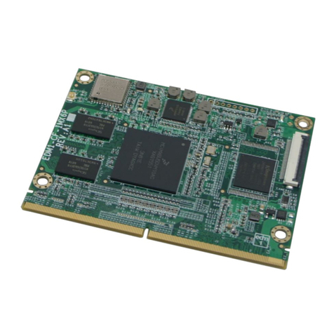
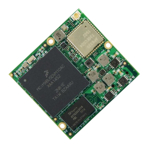
TechNexion FLEX-IMX8M-Mini User manual

FLEX-IMX8M-Mini SYSTEM ON MODULE PRODUCT MANUAL
(WITH NXP i.MX8M Mini SoC)
VER. 1.00
January 31, 2020

FLEX-IMX8M-Mini HARDWARE MANUAL –VER 1.00 –JAN 31 2020
Page 2of 48
REVISION HISTORY
Revision
Date
Originator
Notes
0.1
November 6, 2019
TechNexion
Preliminary
1.00
January 31, 2020
TechNexion
General Public
Release

FLEX-IMX8M-Mini HARDWARE MANUAL –VER 1.00 –JAN 31 2020
Page 3of 48
TABLE OF CONTENTS
1. Introduction .........................................................................................................................................5
1.1. General Introduction.....................................................................................................................5
2. FLEX-IMX8M-Mini Product Overview .................................................................................................5
2.1. FLEX-IMX8M-Mini System-on-Module Overview.........................................................................5
2.2. Block Diagram ..............................................................................................................................6
2.3. Dimensional Drawing....................................................................................................................6
2.4. Component Location ....................................................................................................................7
3. Core Components...............................................................................................................................8
3.1. NXP i.MX8M Mini ARM Cortex-A53 + Cortex-M4 Processor.......................................................8
3.2. Power Management IC (ROHM BD71847)................................................................................10
3.2.1. ROHM BD71847 Reset Signal ............................................................................................10
3.3. Memory.......................................................................................................................................11
3.4. eMMC Storage ...........................................................................................................................11
3.5. Wi-Fi/Bluetooth...........................................................................................................................12
3.6. Atheros AR8035 Gigabit LAN.....................................................................................................15
3.7. JTAG...........................................................................................................................................17
4. FLEX Compute Module Pin Assignment...........................................................................................18
5. FLEX-IMX8M-Mini External Interfaces..............................................................................................27
5.1. Ethernet......................................................................................................................................27
5.2. MIPI Display ...............................................................................................................................28
5.3. MIPI Camera ..............................................................................................................................30
5.4. Audio Interface ...........................................................................................................................32
5.5. PCI Express................................................................................................................................34
5.6. Universal Serial Bus (USB) Interface .........................................................................................35
5.7. SDIO/MMC Interface..................................................................................................................37
5.8. Universal Asynchronous Receiver/Transmitter (UART) Interface..............................................38
5.9. Serial Peripheral Interface (SPI).................................................................................................40
5.10. I2C Bus......................................................................................................................................41
5.10.1. I2C Bit Bang Interface ........................................................................................................41
5.11. General Purpose Input / Output (GPIO)...................................................................................42
5.12. Pulse Width Modulation (PWM) ...............................................................................................43
5.13. Manufacturing and Boot Control...............................................................................................44
5.13.1. eMMC Boot Mode..............................................................................................................44
5.13.2. Serial Downloader Boot Mode...........................................................................................44
5.13.3. SD Card Boot Mode...........................................................................................................44
5.14. Input Power Requirements.......................................................................................................45
5.14.1. Reference and Output Power ............................................................................................45
6. Ordering Information.........................................................................................................................46
6.1. FLEX Compute Module Product Ordering Part Numbers..........................................................46
6.2. Custom Part Number Rule .........................................................................................................46

FLEX-IMX8M-Mini HARDWARE MANUAL –VER 1.00 –JAN 31 2020
Page 4of 48
7. Important Notice................................................................................................................................47
8. Disclaimer .........................................................................................................................................48
LIST OF TABLES
Table 1 –PMIC Signal Description.......................................................................................................10
Table 2 –PMIC Reset Signal Description.............................................................................................10
Table 3 –PMIC Hard Reset Signal Description....................................................................................10
Table 4 –eMMC Signal Description .....................................................................................................11
Table 5 –Wi-Fi Signal Description........................................................................................................13
Table 6 –Bluetooth Signal Description.................................................................................................14
Table 7 - Gigabit Ethernet interconnect between i.MX8M Mini and AR8035 .......................................16
Table 8 - JTAG Signal Description........................................................................................................17
Table 9 –FLEX Compute Module Pin Assignment ..............................................................................18
Table 10 - Ethernet Signal Description .................................................................................................27
Table 11 - MIPI Display Signal Description...........................................................................................29
Table 12 - MIPI Camera Control Signals ..............................................................................................31
Table 13 - I2S-1 Audio Signal Description............................................................................................33
Table 14 - I2S-2 Audio Signal Description............................................................................................33
Table 15 - PCI Express Signal Description...........................................................................................34
Table 16 - USB Host Signal Description...............................................................................................35
Table 17 - USB OTG Signal Description...............................................................................................36
Table 18 - SDIO Signal Description......................................................................................................37
Table 19 –UART3 Signal Description ..................................................................................................39
Table 20 –UART2 Signal Description ..................................................................................................39
Table 21 - SPI Signal Description.........................................................................................................40
Table 22 - I2C Bus Signal Description...................................................................................................41
Table 23 - GPIO Signal Description......................................................................................................42
Table 24 - PWM Signal Description......................................................................................................43
Table 25 - Boot Selection Pins..............................................................................................................44
Table 26 - Serial Downloader Boot Mode Configuration ......................................................................44
Table 27 - SD Card Boot Mode Configuration......................................................................................44
Table 28 - Input Power Signals.............................................................................................................45
Table 29 - Power Management Signals................................................................................................45
LIST OF FIGURES
Figure 1 –FLEX-IMX8M-Mini System-on-Module..................................................................................5
Figure 2 –FLEX-IMX8-Mini System-on-Module Block Diagram Overview ............................................6
Figure 3 –FLEX-IMX8-Mini System-on-Module Dimensions.................................................................6
Figure 4 –FLEX-IMX8M-Mini Top View .................................................................................................7
Figure 5 –FLEX-IMX8M-Mini Bottom View............................................................................................7
Figure 6 –NXP i.MX8M-Mini Processor Blocks......................................................................................9
Figure 7 –FLEX-IMX8M-Mini Wi-Fi Module and Antenna Connector Location ...................................12
Figure 8 –FLEX-IMX8M-Mini JTAG Connector....................................................................................17
Figure 9 –FLEX-IMX8M-Mini Board-to-Board Connectors ..................................................................18

FLEX-IMX8M-Mini HARDWARE MANUAL –VER 1.00 –JAN 31 2020
Page 5of 48
1. Introduction
1.1. General Introduction
The FLEX-IMX8M-Mini is a high performance highly integrated FLEX Compute Module designed
around the NXP i.MX8M Mini Quad core ARM Cortex-A53 + Cortex-M4 applications processor. The
FLEX-IMX8M-Mini provides an ideal building block that easily integrates with a wide range of target
markets requiring compact, cost effective with low power consumption.
The modular approach offered by the FLEX Compute Module gives your project scalability, fast time
to market and upgradability while reducing engineering risk and maintain a competitive total cost of
ownership.
2. FLEX-IMX8M-Mini Product Overview
The FLEX-IMX8M-Mini is a high performance, versatile System-on-Module in FLEX form factor
optimized for audio, voice, video streaming applications.
2.1. FLEX-IMX8M-Mini System-on-Module Overview
The FLEX-IMX8M-Mini System-on-Module has 3 Hirose high-speed 70 pin board-to-board connectors
and integrates the NXP i.MX8M Mini, Memory, eMMC, Power Management IC (PMIC) and Wi-Fi /
Bluetooth features.
Figure 1 –FLEX-IMX8M-Mini System-on-Module

FLEX-IMX8M-Mini HARDWARE MANUAL –VER 1.00 –JAN 31 2020
Page 6of 48
2.2. Block Diagram
Figure 2 –FLEX-IMX8-Mini System-on-Module Block Diagram Overview
2.3. Dimensional Drawing
The FLEX-IMX8-Mini System-on-Module is an ultra-compact module in FLEX form factor.
Figure 3 –FLEX-IMX8-Mini System-on-Module Dimensions

FLEX-IMX8M-Mini HARDWARE MANUAL –VER 1.00 –JAN 31 2020
Page 7of 48
2.4. Component Location
Figure 4 –FLEX-IMX8M-Mini Top View
Figure 5 –FLEX-IMX8M-Mini Bottom View
No.
Description
No.
Description
1
NXP i.MX8M Mini Processor
4
Wi-Fi/Bluetooth Module (optional)
2
Memory IC
5
eMMC Storage IC
3
ROHM BD71847 PMIC
2
1
3
4
5

FLEX-IMX8M-Mini HARDWARE MANUAL –VER 1.00 –JAN 31 2020
Page 8of 48
3. Core Components
3.1. NXP i.MX8M Mini ARM Cortex-A53 + Cortex-M4 Processor
The i.MX 8M Mini is NXP’s first embedded multicore applications processor built using advanced
14LPC FinFET process technology, providing more speed and improved power efficiency. With
commercial and industrial level qualification and backed by NXP’s product longevity program, the i.MX
8M Mini family may be used in any general purpose industrial and IoT application.
For additional details, please refer to the “i.MX8M Mini Applications Processor Reference Manual”.
The i.MX8M Mini has the following features :
•Multicore Processing
o4x Cortex-A53 core platforms up to 1.8GHz per core
o32KB L1-I Cache/ 32 kB L1-D Cache
o512 kB L2 Cache
o1x Arm Cortex-M4 core up to 400MHz
o16 kB L1-I Cache/ 16 kB L2-D Cache
•GPU
o3D GPU (1x shader, OpenGL ES 2.0)
o2D GPU
•Display Interface
o1x MIPI DSI (4-lane) with PHY
•Video Playback
o1080p60 VP9 Profile 0, 2 (10-bit) decoder, HEVC/H.265 decoder, AVC/H.264
Baseline, Main, High decoder, VP8 decoder
o1080p60 AVC/H.264 encoder, VP8 encoder
•Audio
o5x SAI (12Tx + 16Rx external I2S lanes), 8ch PDM input
•Camera Interface
o1x MIPI CSI (4-lane) with PHY
•USB
o2x USB 2.0 OTG controllers with integrated PHY
•PCIe
o1x PCIe 2.0 (1-lane) with L1 low power sub states
•Ethernet
o1x Gigabit Ethernet (MAC) with AVB and IEEE 1588, Energy Efficient Ethernet (EEE)
for low power
•Operating Systems
oLinux, Android, FreeRTOS
•Temperature
oConsumer (0°C to 95°C Tj)
oIndustrial (-40°C to 105°C Tj)
•Package
oFCBGA, 14x14 0.5mm pitch

FLEX-IMX8M-Mini HARDWARE MANUAL –VER 1.00 –JAN 31 2020
Page 9of 48
Figure 6 –NXP i.MX8M-Mini Processor Blocks

FLEX-IMX8M-Mini HARDWARE MANUAL –VER 1.00 –JAN 31 2020
Page 10 of 48
3.2. Power Management IC (ROHM BD71847)
The FLEX-IMX8M-Mini has an on onboard ROHM BD71847 power management integrated circuit
(PMIC) that features a configurable architecture supporting the numerous outputs with various current
ratings as well as programmable voltage and sequencing required by the components on the FLEX-
IMX8M-Mini module.
Table 1 –PMIC Signal Description
CPU
BALL
CPU PAD
NAME
Pinmux
(mode)
Signal
I/O
Description
E13
I2C4_SDA
I2C4_SDA
SDA
I/O
I2C bus data line
D13
I2C4_SCL
I2C4_SCL
SCL
I
I2C bus clock line
B24
POR_B
POR_B
POR_B
O
PMIC Reset Signal
A24
PMIC_ON_R
EQ
PMIC_ON_RE
Q
PMIC_ON_R
EQ
I
PMIC Power on request Input
from processor (this signal has
an external pull-up resistor)
E24
PMIC_STBY
_REQ
PMIC_STBY_
REQ
PMIC_STBY
_REQ
I
PMIC Power standby request
input from processor
K24
NAND_DAT
A01
GPIO3_IO07
IRQ_B
O
PMIC Interrupt Signal
F24
RTC_RESET
_B
RTC_RESET_
B
RTC_RESET
_B
O
PMIC RTC Reset Signal
A26
RTC_XTALI
RTC_XTALI
C32K_OUT
O
32.768 KHz Clock
AG12
GPIO1_IO04
USDHC2_VSE
LECT
SD_VSELEC
T
O
SD Card Voltage Selection
Signal (on module only)
3.2.1. ROHM BD71847 Reset Signal
To perform a hard-reset of the FLEX-IMX8M-Mini a software reset signal can be implemented. By
connecting a Watchdog circuit on the carrier board by using PIN 238
Table 2 –PMIC Reset Signal Description
CPU
BALL
CPU PAD
NAME
Pinmux (mode)
Signal
V
I/O
Description
AG13
GPIO1_IO02
WDOG1_B
WDOG_B
3V3
I
Connected to the
WDOG_B signal of
PMIC and i.MX8M-Mini
SoC
To perform a hard-reset of the FLEX-IMX8M-Mini an external circuit (for example a button or external
watchdog IC) can be integrated on the carrier board by using PIN 238.
Table 3 –PMIC Hard Reset Signal Description
Connector
Signal
V
I/O
Description
9
PWRON_B
1V8
I
Connected to Reset Power Signal of PMIC

FLEX-IMX8M-Mini HARDWARE MANUAL –VER 1.00 –JAN 31 2020
Page 11 of 48
3.3. Memory
The FLEX-IMX8M-Mini integrates Low Power Double Data Rate IV (LPDDR4) Synchronous DRAM is
connected over a 32-Bit dual channel configuration. (16 bit per channel).
The following memory chip manufacturers have been validated and tested on the FLEX-IMX8M-Mini
Compute Module:
•SKHynix
•Kingston
•Micron
•Samsung
•ISSI
3.4. eMMC Storage
The FLEX-IMX8M-Mini can be ordered with onboard eMMC storage in different configurations and
capacity. The onboard eMMC device is connected on the USDHC3 pins of the i.MX8M Mini processor
in an 8-bit width configuration.
The following eMMC chip manufacturers have been validated and tested on the FLEX-IMX8M-Mini
System-on-Module:
•Kingston eMMC
•Micron eMMC
•Sandisk iNAND
Table 4 –eMMC Signal Description
CPU
BALL
CPU PAD NAME
Signal
V
I/O
Description
M26
NAND_DATA04
USDHC3_DATA0
1V8
I/O
MMC/SDIO Data bit 0
L26
NAND_DATA05
USDHC3_DATA1
1V8
I/O
MMC/SDIO Data bit 1
K26
NAND_DATA06
USDHC3_DATA2
1V8
I/O
MMC/SDIO Data bit 2
N26
NAND_DATA07
USDHC3_DATA3
1V8
I/O
MMC/SDIO Data bit 3
N27
NAND_RE_B
USDHC3_DATA4
1V8
I/O
MMC/SDIO Data bit 4
M27
NAND_CE2_B
USDHC3_DATA5
1V8
I/O
MMC/SDIO Data bit 5
L27
NAND_CE3_B
USDHC3_DATA6
1V8
I/O
MMC/SDIO Data bit 6
K27
NAND_CLE
USDHC3_DATA7
1V8
I/O
MMC/SDIO Data bit 7
R27
NAND_WP_B
USDHC3_CMD
1V8
I/O
MMC/SDIO Command
R26
NAND_WE_B
USDHC3_CLK
1V8
O
MMC/SDIO Clock
P27
NAND_CE1_B
USDHC3_STROBE
1V8
O
This signal is generated by the device
and used for output in HS400 Mode

FLEX-IMX8M-Mini HARDWARE MANUAL –VER 1.00 –JAN 31 2020
Page 12 of 48
3.5. Wi-Fi/Bluetooth
The FLEX-IMX8M-Mini has an optional pre-certified high-performance TechNexion PIXI-9377 dual
band 2.4/5Ghz Wi-Fi / Bluetooth 5 Qualcomm Atheros QCA9377 based module on board.
The PIXI-9377 Wi-Fi / Bluetooth module is designed to operate with a single antenna for Wi-Fi and
Bluetooth by using the MHF4 connector.
Key Features of the PIXI-9377 are:
•IEEE 802.11 ac/a/b/g/n 2.4 / 5Ghz
•Bluetooth 5
•MHF4 antenna connector
•Linux and Android drivers
•Wi-Fi / BT module board certifications with multiple antennas:
oFCC (USA)
oIC (Canada
oETSI (Europe)
oGiteki / Telec (Japan)
oRCM / C-tick (Australia / New Zealand).
•Industrial operation temperature range: -40°C to +85°C
The following pre-certified matching antennas are available with our distributors.
Partnumber
Description
ANTP180A138045D2450MHF4
4.5dBi dipole antenna
ANTP180A207070D2450MHF4
7dBi dipole antenna
ANTP150P232525D2450MHF4
2.5dBi PCB patch antenna
Figure 7 –FLEX-IMX8M-Mini Wi-Fi Module and Antenna Connector Location

FLEX-IMX8M-Mini HARDWARE MANUAL –VER 1.00 –JAN 31 2020
Page 13 of 48
Table 5 –Wi-Fi Signal Description
i.MX8M
BALL
PAD NAME
Signal
I/O
Description
Y27
SD1_DATA0
USDHC1_DATA0
I/O
MMC/SDIO Data bit 0
Y26
SD1_DATA1
USDHC1_DATA1
I/O
MMC/SDIO Data bit 1
T27
SD1_DATA2
USDHC1_DATA2
I/O
MMC/SDIO Data bit 2
T26
SD1_DATA3
USDHC1_DATA3
I/O
MMC/SDIO Data bit 3
V27
SD1_CMD
USDHC1_CMD
I/O
MMC/SDIO Command
V26
SD1_CLK
USDHC1_CLK
O
MMC/SDIO Clock
N22
NAND_ALE
GPIO3_IO00
WL_HOST_WAKE
O
Host wake up. Signal from the module
to the host indicating that the module
requires Attention.
• Asserted: Host device must wake-up
or remain awake.
• Deserted: Host device may sleep
when sleep criteria are met.
The polarity of this signal is software
configurable and can be asserted high
or low.
AG14
GPIO1_IO00
GPIO1_IO00
WL_REG_ON
O
Wi-Fi device wake-up: Signal from the
host to the module indicating that the
host requires attention.
• Asserted: Wi-Fi device must wake-up
or remain awake.
• Deserted: Wi-Fi device may sleep
when sleep criteria are met.
The polarity of this signal is software
configurable and can be asserted high
or low.

FLEX-IMX8M-Mini HARDWARE MANUAL –VER 1.00 –JAN 31 2020
Page 14 of 48
Table 6 –Bluetooth Signal Description
i.MX8M
BALL
PAD NAME
Signal
I/O
Description
F13
UART1_TXD
UART1_TXD
O
Bluetooth UART Serial Input. Serial
data input for the HCI UART Interface
E14
UART1_RXD
UART1_RXD
I
Bluetooth UART Serial Output. Serial
data output for the HCI UART
Interface.
E18
UART3_RXD
UART1_CTS
I/O
Bluetooth UART Clear to Send.
Active-low clear-to-send signal for the
HCI UART interface.
D18
UART3_TXD
UART1_RTS
I/O
Bluetooth UART Request to Send.
Active-low request-to-send signal for
the HCI UART interface.
AG15
SAI1_RXD0
SAI1_RXD0
I
Integrated Interchip Sound (I2S)
channel receive data line
AG20
SAI1_TXD0
SAI1_TXD0
O
Integrated Interchip Sound (I2S)
channel transmit data line
AC18
SAI1_TXC
SAI1_TXC
O
Integrated Interchip Sound (I2S)
channel word clock signal
AB19
SAI1_TXFS
SAI1_TXFS
O
Integrated Interchip Sound (I2S)
channel frame synchronization signal
P26
NAND_READY_B
GPIO3_IO16
BT_HOST_WAKE
I
Host UART wake up. Signal from the
module to the host indicating that the
module requires Attention.
• Asserted: Host device must wake-up
or remain awake.
• Deserted: Host device may sleep
when sleep criteria are met.
The polarity of this signal is software
configurable and can be asserted high
or low.
AF13
GPIO1_IO03
GPIO1_IO03
BT_REG_ON
O
Bluetooth device wake-up: Signal from
the host to the module indicating that
the host requires attention.
• Asserted: Bluetooth device must
wake-up or remain awake.
• Deserted: Bluetooth device may
sleep when sleep criteria are met.
The polarity of this signal is software
configurable and can be asserted high
or low.

FLEX-IMX8M-Mini HARDWARE MANUAL –VER 1.00 –JAN 31 2020
Page 15 of 48
3.6. Atheros AR8035 Gigabit LAN
The FLEX-IMX8M-Mini connects the i.MX8M Mini processor RGMII interface to the Atheros AR8035
gigabit Ethernet chip.
The AR8035 supports IEEE 802.3az EEE standard (Energy Efficient Ethernet) and Atheros
proprietary SmartEEE. SmartEEE allows legacy MAC/SoC devices without 802.3az support to
function as a complete 802.3az system.
Features:
•10/100/1000 BASE-T IEEE 802.3 compliant
•Supports 1000 BASE-T PCS and auto-negotiation with next page support
•Supports RGMII and/or SGMII interfaces to MAC devices
•Supports Fibre and Copper combo mode when MAC interface works in RGMII mode
•Supports additional IEEE 1000 BASE-X and 100 BASE-FX with Integrated SerDes
•RGMII timing modes support internal delay and external delay on Rx path
•Supports Atheros Green ETHOS® power saving modes with internal automatic DSP power
saving scheme
•Supports IEEE 802.3az (Energy Efficient Ethernet) n Supports SmartEEE which allows MAC/
SoC devices without 802.3az support to function as the complete 802.3az system
•Fully integrated digital adaptive equalizers, echo cancellers, and Near End Crosstalk (NEXT)
cancellers
•Supports Synchronous Ethernet with selectable recovered clock output
•Robust Cable Discharge Event (CDE) protection of ±6 kV
•Error-free operation over up to 140 meters of CAT5 cable
•Automatic channel swap (ACS)
•Automatic MDI/MDIX crossover
•Automatic polarity correction
•IEEE 802.3u compliant Auto-Negotiation
•Jumbo Frame support up to 10KB (full duplex)
•Multiple loopback modes for diagnostics
•Robust Surge Protection with ±750 V/ differential mode and ±4 kV/common mode
•Cable Diagnostic Test (CDT)
For more information, please contact your TechNexion sales representative.

FLEX-IMX8M-Mini HARDWARE MANUAL –VER 1.00 –JAN 31 2020
Page 16 of 48
Table 7 - Gigabit Ethernet interconnect between i.MX8M Mini and AR8035
CPU
BALL
PAD NAME
Signal
AR8035
PIN
Description
AG24
ENET_TXC
ETH_TXCLK
33
RGMII transmit clock
AG26
ENET_TD0
ETH_TXD0
34
RGMII transmit data 0
AF26
ENET_TD1
ETH_TXD1
35
RGMII transmit data 1
AG25
ENET_TD2
ETH_TXD2
36
RGMII transmit data 2
AF25
ENET_TD3
ETH_TXD3
37
RGMII transmit data 3
AF24
ENET_TX_CTL
ETH_TXEN
32
RGMII transmit enable
AE26
ENET_RXC
ETH_RXCLK
31
RGMII receive clock
AE27
ENET_RD0
ETH_RXD0
29
RGMII receive data 0
AD27
ENET_RD1
ETH_RXD1
28
RGMII receive data 1
AD26
ENET_RD2
ETH_RXD2
26
RGMII receive data 2
AC26
ENET_RD3
ETH_RXD3
25
RGMII receive data 3
AF27
ENET_RX_CTL
ETH_RXDV
30
RGMII receive data valid
AC27
ENET_MDC
MDC
40
Management data clock reference
AB27
ENET_MDIO
MDIO
39
Management data
R23
SD1_RESET_B
ENET_nRST
1
System reset
R24
SD1_STROBE
ENET_nINT
20
Ethernet interrupt output
N24
ENET_PWR_EN
ENET_PWR_EN
3
Ethernet Power enable

FLEX-IMX8M-Mini HARDWARE MANUAL –VER 1.00 –JAN 31 2020
Page 17 of 48
3.7. JTAG
The FLEX-IMX8M-Mini has an on module JTAG Controller that provides debug and test control with
maximum security. The test access port is designed to support features compatible with the IEEE
standard 1149.1 v2001 (JTAG). Support IEEE P1149.6 extensions to the JTAG standard are for AC
testing of selected IO signals.
The JTAG port allows debug-related control and status, such as putting selected cores into
reset and/or debug mode and the ability to monitor individual core status signals via JTAG.
JTAG port interfaces the M4 and Cortex A53 Cores DAP - debug access port.
For additional details, please refer to the “i.MX8M Mini Applications Processor Reference Manual”.
Figure 8 –FLEX-IMX8M-Mini JTAG Connector
NOTE : Pin 1 is far most thru-hole. Pin 8 is closest to the Wi-Fi / Bluetooth interface.
Table 8 - JTAG Signal Description
PIN
CPU BALL
Description
1
3V3
VDD_3V3 Signal
2
C27
JTAG_nTRST
3
F27
JTAG_TMS
4
E27
JTAG_TDI
5
E26
JTAG_TDO
6
NC
Not Connected
7
F26
JTAG_TCK
8
GND
Ground Signal

FLEX-IMX8M-Mini HARDWARE MANUAL –VER 1.00 –JAN 31 2020
Page 18 of 48
4. FLEX Compute Module Pin Assignment
Figure 9 –FLEX-IMX8M-Mini Board-to-Board Connectors
Table 9 –FLEX Compute Module Pin Assignment
PIN
CPU
BALL
CPU PAD NAME
Signal
V
I/O
Description
1
VSYS
5V0
P
System input power
(4.75 to 5.25V)
2
VSYS
5V0
P
System input power
(4.75 to 5.25V)
3
VSYS
5V0
P
System input power
(4.75 to 5.25V)
4
VSYS
5V0
P
System input power
(4.75 to 5.25V)
5
VSYS
5V0
P
System input power
(4.75 to 5.25V)
6
VSYS
5V0
P
System input power
(4.75 to 5.25V)
7
3V3_REF
3V3
P
3.3V Reference
Voltage for I/O
8
3V3_VDD
3V3
P
3.3V Output Voltage
9
SYS_nRST
1V8
I
Power Reset pin
connected to PMIC
10
GND
P
Ground
11
GND
P
Ground
12
AR8035 pin 9
GBE_MDI0+
2V5
I/O
Gigabit Ethernet
Media Dependent
Interface (MDI)
differential pair 0
positive signal
13
AR8035 pin 15
GBE_MDI2+
2V5
I/O
Gigabit Ethernet
Media Dependent
Interface (MDI)
differential pair 2
positive signal
14
AR8035 pin 10
GBE_MDI0-
2V5
I/O
Gigabit Ethernet
Media Dependent
Interface (MDI)
differential pair 0
negative signal
15
AR8035 pin 16
GBE_MDI2-
2V5
I/O
Gigabit Ethernet
Media Dependent

FLEX-IMX8M-Mini HARDWARE MANUAL –VER 1.00 –JAN 31 2020
Page 19 of 48
Interface (MDI)
differential pair 2
negative signal
16
GND
P
Ground
17
GND
P
Ground
18
AR8035 pin 12
GBE_MDI1+
2V5
I/O
Gigabit Ethernet
Media Dependent
Interface (MDI)
differential pair 1
positive signal
19
AR8035 pin 18
GBE_MDI3+
2V5
I/O
Gigabit Ethernet
Media Dependent
Interface (MDI)
differential pair 3
positive signal
20
AR8035 pin 13
GBE_MDI1-
2V5
I/O
Gigabit Ethernet
Media Dependent
Interface (MDI)
differential pair 1
negative signal
21
AR8035 pin 19
GBE_MDI3-
2V5
I/O
Gigabit Ethernet
Media Dependent
Interface (MDI)
differential pair 3
negative signal
22
GND
P
Ground
23
GND
P
Ground
24
AR8035 pin 24
LED1_nLink100
2V5
O
Gigabit Ethernet
100Mbit/sec LED link
indicator
25
AR8035 pin 21
LED1_ACT
2V5
O
Gigabit Ethernet LED
Activity indicator
26
AR8035 pin 22
LED1_nLink1000
2V5
O
Gigabit Ethernet
1000Mbit/sec LED
link indicator
27
AR8035 pin 21
LED1_ACT_GND
GND
O
Gigabit Ethernet LED
Activity indicator
Ground Pin
28
GND
P
Ground
29
GND
P
Ground
30
NC
Not Connected
31
A9
MIPI_DSI_D0_N
MIPI_DSI_D0_N
1V8
O
MIPI Display Serial
Interface data pair 0
negative signal
32
NC
Not Connected
33
B9
MIPI_DSI_D0_P
MIPI_DSI_D0_P
1V8
O
MIPI Display Serial
Interface data pair 0
positive signal
34
GND
P
Ground
35
GND
P
Ground
36
NC
Not Connected
37
A10
MIPI_DSI_D1_N
MIPI_DSI_D1_N
1V8
O
MIPI Display Serial
Interface data pair 1
negative signal
38
NC
Not Connected
39
B10
MIPI_DSI_D1_P
MIPI_DSI_D1_P
1V8
O
MIPI Display Serial
Interface data pair 1
positive signal
40
GND
P
Ground

FLEX-IMX8M-Mini HARDWARE MANUAL –VER 1.00 –JAN 31 2020
Page 20 of 48
41
GND
P
Ground
42
NC
Not Connected
43
A12
MIPI_DSI_D2_N
MIPI_DSI_D2_N
1V8
O
MIPI Display Serial
Interface data pair 2
negative signal
44
NC
Not Connected
45
B12
MIPI_DSI_D2_P
MIPI_DSI_D2_P
1V8
O
MIPI Display Serial
Interface data pair 2
positive signal
46
GND
P
Ground
47
GND
P
Ground
48
NC
Not Connected
49
A13
MIPI_DSI_D3_N
MIPI_DSI_D3_N
1V8
O
MIPI Display Serial
Interface data pair 3
negative signal
50
NC
Not Connected
51
B13
MIPI_DSI_D3_P
MIPI_DSI_D3_P
1V8
O
MIPI Display Serial
Interface data pair 3
positive signal
52
GND
P
Ground
53
GND
P
Ground
54
NC
Not Connected
55
A11
MIPI_DSI_CLK_
N
MIPI_DSI_CLK_N
1V8
O
MIPI Display Serial
Interface clock pair
negative signal
56
NC
Not Connected
57
B11
MIPI_DSI_CLK_
P
MIPI_DSI_CLK_P
1V8
O
MIPI Display Serial
Interface clock pair
positive signal
58
GND
P
Ground
59
GND
P
Ground
60
NC
Not Connected
61
AF8
SPDIF_EXT_CLK
PWM1_OUT
3V3
O
General Purpose
Input Output with
PWM control for MIPI
DSI Brightness
Control
(DSI_BL_PWM)
62
NC
Not Connected
63
AD10
GPIO1_IO10
GPIO1_IO10
3V3
I/O
General Purpose
Input Output MIPI
DSI Display enable
signal (DSI_EN)
64
NC
Not Connected
65
AC10
GPIO1_IO11
GPIO1_IO11
3V3
I/O
General Purpose
Input Output MIPI
DSI Display reset
signal (DSI_RST)
66
NC
Not Connected
67
AB10
GPIO1_IO12
GPIO1_IO12
3V3
I/O
General Purpose
Input Output MIPI
DSI Display power
enable (DSI_VDDEN)
68
GND
P
Ground
69
GND
P
Ground
70
A16
MIPI_CSI_CLK_
N
MIPI_CSI_CLK_N
1V8
O
MIPI Camera Serial
Interface clock pair
negative signal
71
NC
Not Connected
Table of contents
Other TechNexion Control Unit manuals

TechNexion
TechNexion PIXI-9377 User manual

TechNexion
TechNexion PICO-IMX6UL-EMMC User manual

TechNexion
TechNexion PICO-IMX6 User manual

TechNexion
TechNexion PICO-IMX8M User manual

TechNexion
TechNexion EDM1-IMX6 User manual

TechNexion
TechNexion EDM1-IMX6PLUS User manual

TechNexion
TechNexion XORE-WIZARD-IMX8M-MINI User manual

TechNexion
TechNexion TAM-3517 User manual

TechNexion
TechNexion PICO-WIZARD-IMX8M-MINI User manual