E-T-A E-1071-623 User manual

www.e-t-a.de
Elektronik-Schutzschaltrelais E-1071-623/627
6- 49
6
2011/12
Das E-T-A-Stromhalbleiterrelais E-1071-62. ist ein elektronischer Steu-
erbaustein für induktive DC 24 V - Lasten (z. B. Magnetventile, Mag-
netbremsen).
Es wird eingesetzt um:
• die Verbraucher sicher und schnell zu schalten
• die elektrische Funktionsfähigkeit der Verbraucher zu überwachen
• unterschiedliche Leitungslängen zu kompensieren
Das Stromhalbleiterrelais muss mit einer höheren Spannung
(DC 28...60 V) als die Verbraucher-Nennspannung (DC 24 V)
betrieben werden, da der Laststrom elektronisch geregelt wird
(getaktete Betriebsart). Dadurch ist gewährleistet, dass in einer
Industrieanlage mit unterschiedlichen Leitungslängen (Lastleitungen)
jedem Verbraucher eine erhöhte Anzugsleistung zur Verfügung
gestellt werden kann. Im Haltebetrieb wird der Laststrom dann auf
einen kleineren Wert (ca. 60 % des Nennstromes) zurückgeregelt.
Dadurch verringert sich die Betriebstemperatur des Verbrauchers und
dessen Lebensdauer steigt.
Der zweipolige elektronische Schaltausgang verhindert den unbe-
absichtigten Anlauf oder die Möglichkeit der gefahrbringenden
Bewegung einer Maschine, wie sie bei einem Erdschluss in einer
Anlage mit erdfreiem Stromversorgungsnetz (»IT-System«) auftreten
kann (vgl. EG-Maschinen-richtlinie bzw. EN 60204 Teil 1 »Elektrische
Ausrüstung von Maschinen«, Abs. 9.4.3.1).
Beschreibung
E-1071-623
●induktive Aktoren wie Magnetventile und Magnetkupplungen in
Maschinen und Anlagen zweipolig zu schalten
●die elektrische Funktionsfähigkeit dieser Verbraucher zu überwachen
●die Leitungen des Lastkreises zu schützen und zu überwachen
●den Betriebszustand zu signalisieren sowie Lastkreisfehler optisch
(LEDs bzw. Auslöseknopf ROT) und über potentialfreie Statusaus-
gänge zu melden
●im Überlast- bzw. Kurzschlussfall oder durch Handabschaltung den
Lastkreis zweipolig über Relaiskontakte aufzutrennen
Das Gerät wird eingesetzt, um …
Wesentliche Merkmale
●Nur für induktive DC 24 V-Verbraucher geeignet
●Individuelle Anpassung an verschiedene Verbraucher
Standard: IN= 0,1…3,1 A bzw. 10 mA...310 mA
●Durch getaktete Betriebsweise erhebliche Reduzierung der Verlust-
leistung im Verbraucher
●Zweipoliger Schaltausgang, kurzschlussfest mit galvanische Trennung
vom Netz
●Überwachung des Einschaltstromes und des Haltestromes
●Galvanische Trennung:
- Optokoppler im Steuerkreis
- Galvanische Trennung des Lastkreises, handbetätigt oder
wenn Kurzschluss
- Optokoppler für Statusausgänge
●Verpolschutz und Überspannungsschutz im Steuerkreis,
Lastkreis und Statuskreis
●Steuerstromanzeige LED GELB
●O.K. - Meldung LED GRÜN
●Drahtbruchmeldung LED ROT
●Fehlermeldung LED ROT
(Kurzschluss, Unter-/Überspannung, Falscheinstellung)
●Zwei Statusausgänge für SPS zur Auswertung (Funktionsmeldung,
Betriebsmeldung)
●Integrierte Schnellabschaltung (keine Freilaufdiode an Last an-
schließen, Freilaufstrom wird elektronisch geregelt!)
Abschaltzeit < Einschaltzeit!
Technische Daten (TU= 25 °C, UB= DC 48 V)
Nennspannung DC 48 V
Betriebsspannung UBDC 28...60 V
(siehe Funktionsbeschreibung)
Nennstrom IN0,1...3,1 A Var. 1 bzw.
10...310 mA Var. 2 einstellbar über
Schalter und Potentiometer, frontseitig
Stromaufnahme I0
(US= »0«) typ. 16 mA
Restwelligkeit für alle
Spannungen max. 5 % (Drehstrombrücke)
Verpolschutz UB(Klemmen 1 und 2) im Gerät integriert
Fail Save Sicherung
Isolationsspannung 1,5 KV zwischen Last-, Steuer- und
Statusmeldekreis
Lastkreis
Lastausgang zweipolig, Tranistor plus- und minus-
schaltend, getaktet (ca. 180 Hz)
Nenndaten der Last DC 24 V/0,1...3,1 A bzw.
DC 24 V/10...310 mA einstellbar
Einschaltstrom IEbis ca. 10 % über Ankeranzugsstrom
Haltestrom IHtyp. 60 % des eingestellten Nennstromes IN
Kurzschlussabschaltstrom ca. 4,5 A
Drahtbruchüberwachung im ein- und ausgeschalteten Zustand
(Drahtbruch-LED ROT leuchtet bei
offenem Lastkreis)
Galvanische Trennung erfolgt 2-polig im Lastpfad,
durch Handauslösung des
Schutzschalters oder nach Kurzschlussabschaltung
Strommessbuchsen 2 x ø 2 mm (stromproportionale
Spannung: 1 V = 1 A )
Freilauf elektronische Regelung mit
(siehe auch Funktionsbeschreibung) Schnellabschaltung, im Gerät integriert
Steuerkreis
Ansteuerung Optokoppler im Steuereingang
Steuerspannung US»0« = DC 0…5 V
»1« = DC 8,5…35 V
Steuerstrom IStyp. 5...10 mA
Schaltfrequenz fmax 1 Hz
Ansteueranzeige (US= »1«) LED GELB leuchtet (ISfließt)
Schutz Verpolschutz (Diode)
Statusausgänge
2 Meldeausgänge Betriebsmeldung/Funktionsmeldung
- galvanisch getrennt über Optokoppler
- Transistorausgänge plusschaltend
- Hilfsspannung UA: DC 12...60 V
- max. 50 mA je Ausgang
- integrierte Freilaufdiode
- Verpol- und Überspannungsschutz
Betriebsmeldung (Klemme 8) U
S= »0« : Ausgang gesperrt
< 70 ms Ausschaltmeldeverzögerung
U
S= »1« : Ausgang schaltet Pluspotential
(Kl. 10) auf Kl. 8
nur solange Laststrom fließt,
nicht bei DB und KS
< 15 ms Einschaltmeldeverzögerung
Funktionsmeldung (Klemme 9) Störung: Ausgang gesperrt
keine Störung: Ausgang schaltet Plus-
potential (Kl. 10) auf Kl. 9
^
UE
N

Elektronik-Schutzschaltrelais E-1071-623/627
6
www.e-t-a.de
6- 50 2011/12
Funktionsbeschreibung
Technische Daten
Allgemeine Daten
Umgebungstemperatur 0…60 °C (ohne Betauung)
Feuchte Wärme Prüfung nach IEC 60068-2-78, Test Cab
96 Std. in 95 % rel. Feuchte,
Temperatur 40 °C
Vibrationsfestigkeit Prüfung nach IEC 60068-2-6, Test Fc
3 g (10-500 Hz)
Anschlussklemmen: 1071-623: Schraubklemmen
1071-627: Käfigzugfedern
Anschluss: max. 2 x 2,5 mm2massiv
max. 2 x 1,5 mm2Litze mit
Hülse, nach DIN 46228
Gehäuse: Klemmplatte Polycarbonat GV, blau
Haube Polycarbonat, schwarz
Gehäusebefestigung Schnappbefestigung auf Hutschiene
DIN 50022-35
Brennverhalten (Gehäuse) nach UL 94: V = 0 VDE 0304: Stufe 1
Schutzart Gehäuse, Klemmen IP20 DIN 40050
Einbaumaße 45 x 74 x 128 mm
Gewicht ca. 170 g
Betriebsspannung UB
Die maximale Betriebsspannung des Halbleiterrelais liegt bei DC 60 V.
Die, für 24 V-Ventile nötige, minimale Betriebsspannung ist abhängig
vom gesamten ohmschen Widerstand im Lastkreis.
Die Höhe des Einschaltstromes wird verringert durch:
- Spannungsabfall auf der Lastleitung
- Widerstandserhöhung des angeschlossenen Verbrauchers durch
seine eigene Betriebstemperatur.
Minimale Betriebsspannung UBmin
Bei Unterschreitung der min. Betriebsspannung UB min = 28 V ist die
Verbraucherleistung nicht mehr garantiert. Die LED ROT (Fehler) leuchtet,
der Ausgang wird abgeschaltet. Erst wenn 29,4 V wieder überschrit-
ten werden, wird die Last wieder eingeschaltet und der normale
Betriebszustand ist wieder hergestellt.
Widerstandserhöhung im Lastkreis:
1,5 mm2-Kabel ca. 2,8 Ω/100 m Entfernung
2,5 mm2-Kabel ca. 1,6 Ω/100 m Entfernung
Maximale Betriebsspannung UBmax
Bei Überschreitung der max. Betriebsspannung UBmax = 60 V ist die
Verbraucherleistung nicht mehr garantiert.
Die LED ROT (Fehler) leuchtet, der Ausgang wird abgeschaltet.
Erst wenn 57 V wieder unterschritten werden, wird die Last wieder
eingeschaltet und der normale Betriebszustand ist wieder herge-
stellt.
ca. 10...100 ms
Zeit t
IH
IN
Strom
Ein
IN= Nennstrom
IE= Einschaltstrom/
Ankeranzugsstrom
IH= Haltestrom
Aus
Schnell-
abschaltung
IE
Einschaltstrom IE = Ankeranzugsstrom
Der Ausgangstransistor schaltet bis zum tatsächlichen Einschalten des
Ventils (Ankeranzugsstrom) die angeschlossene Betriebsspannung
auf den induktiven Verbraucher, anschließend wird der Laststrom auf
den Haltestrom IHzurückgeregelt.
Nennstrom IN, Haltestrom IH
Der Nennstrom INdes jeweiligen Verbrauchers bei seiner Nenn-
spannung muss im Bereich 0,1...3,1 A eingestellt werden. Der Hal-
testrom IHdes Verbrauchers wird intern auf 60 % des eingestellten
Nennstromes geregelt. Dieser Haltestrom kann im Betrieb an den
2 mm-Strom-Messbuchsen (stromproportionale Spannung: 1 V = 1 A)
mit einem Voltmeter gemessen werden.
Funktionsbeschreibung
1 2 3 4 5
Steuerstrom
O.K.
Fehler
Drahtbruch
ILast
= 0,6 x IN
+IN/A
2
1
0
6 7 8 9 10
0,2
0,4 0,6 0,8
1,0
0,1 1,1
DC 24 V-Last
0,1-3,1 A
GERMANY
1V =1A
^
E-1071-623
+
Nennstromeinstellung (Beispiel für 0,1...3,1 A einstellbar)
Der Nennstrom wird mit einem Drehschalter
(Schalterstellung 0 A - 1 A - 2 A) und einem 270 ° Potentiometer
(Einstellbereich 0,1 A...1,1 A) eingestellt.
Durch Addition beider Einstellungen erhält man den Nennstrom IN
des Verbrauchers.
Beispiel: 24 V-Verbraucher mit IN= 1,5 A
Einstellen: Schalter-Stellung 1 A + Potentiometer-Stellung 0,5 A
Achtung bei Stromstärke 0,01...0,31 A: Bei Verwendung von
Ventilstecker mit LED, muss deren Stromaufnahme bei der
Nennstromeinstellung berücksichtigt werden.
Nennstrom-Falscheinstellung
Fehler-LED ROT blinkt wenn Falscheinstellung vorliegt. Erst nach
etwa 15 sec, wenn derzeit keine Richtigstellung des Nennstromwertes
erfolgt, wird Last abgeschaltet und die Fehler-LED ROT leuchtet dau-
ernd. Reset nur über Wiedereinschalten möglich.
Der Toleranzbereich, in dem noch keine Falscheinstellung signalisiert
wird, liegt bei ca. ± 30 % des Haltestroms.
^
INQuerschnitt UB min bei Leitungslänge
2 x 50 m 2 x 100 m 2 x 200 m 2 x 300 m
1 A 1,5 mm2
2,5 mm2
DC 33 V
DC 32 V
DC 35 V
DC 33 V
DC 37 V
DC 35 V
DC 40 V
DC 37 V
2 A 1,5 mm2
2,5 mm2
DC 35 V
DC 34 V
DC 38 V
DC 35 V
DC 44 V
DC 39 V
DC 49 V
DC 42 V
3 A 1,5 mm2
2,5 mm2
DC 37 V
DC 35 V
DC 41 V
DC 38 V
DC 50 V
DC 42 V
DC 58 V
DC 48 V

www.e-t-a.de
Elektronik-Schutzschaltrelais E-1071-623/627
6- 51
6
2011/12
Blockschaltbild
0
1
2+
Nennstrom
Voreinstellung
Galvanische
Trennung
off
1
3
4
2
Ventillast
+
-
(28...60 V DC)
stromproportionaler
Spannungs-Ausgang U(I)
+-
LED-Anzeige
gb gn rt rt
Steuer- und
Überwachungs-
elektronik
8
5
6
7
9
10
-US
+US
-Ua
SB
SF
+Ua
+UB
-UB
Status
Funktion
Status
Betrieb
max. 35 V DC
max. 60 V DC/0,1 A
Steuer-
eingang
Steuereingang
O. K.
Drahtbruch
Fehler
Betriebszustände
Betriebszustand Störungsfreier
Betrieb
Drahtbruch Last-Kurzschluss
-HSS nach
GND(1)
-LSS nach UB(2)
UBzu
niedrig/hoch(3)
Falschein-
stellung
Steuereingang
(Klemme 6 und 7) »0« »1« »0« »1« »0« »1« »0« »1«
LED GELB -Steuerstrom
LED GRÜN - O. K.
LED ROT - Drahtbruch
LED ROT - Fehler
0
1
0
0
1
1
0
0
0
0
1
0
1
0
1
0
0
0
0
1
1
0
0
1
0
0
0
1
1
0
0
1
Status Funktion
(Klemme 9)
Status Betrieb
(Klemme 8)
1
0
1
1
0
0
0
0
0
0
0
0
0
0
0
0
Galvanische Trennung 00001 1 0 0
Bemerkungen:
(1) Kurzschluss HSS nach GND bed. plusschaltender Transistor ist
nach Masse verbunden
(2) Kurzschluss LSS nach UBbed. minusschaltender Transistor ist
nach UBverbunden
(3) Unterspannung: Gerät schaltet bei 28 V aus und bei 29,4 V wieder ein.
Überspannung: Gerät schaltet bei 60 V aus und bei 57 V wieder ein.
1 - LED leuchtet, Statusausgang führt Plus-Potential
0 - LED leuchtet nicht, Statusausgang gesperrt
Bestellnummernschlüssel
Typennummer
E-1071 Schutzschaltrelais
Anschlussklemmen
623 Schraubklemmen
627 Käfigzugfedern
Verbraucher - Nennspannung
DC 24 V
Nennstrom
0,1 A...3,1 A (Standard)
0,01 A...0,31 A
E-1071 - 623 - DC 24 V - 0,1 A...3,1 A Bestellbeispiel

Elektronik-Schutzschaltrelais E-1071-623/627
6
www.e-t-a.de
6- 52 2011/12
Maßbild
129 AUS-Zustand
45
73,2
Hutschiene EN 50022-35x7,5
(nicht im Lieferumfang enthalten)
124 EIN-Zustand
121
119,5

www.e-t-a.de
Elektronik-Schutzschaltrelais E-1071-623/627
6- 53
6
2011/12
Anschlussbilder
E-1071-623 (0,1...3,1 A) E-1071-623 (10...310 mA)
E-1071-627 (0,1...3,1 A) E-1071-627 (10...310 mA)
Klemme:
1+UB(Betriebsspannung Plus: max. DC 60 V)
2 - UB(Betriebsspannung Minus)
3 Last (+)
4 Last (-)
5 -UA(Hilfsspannung Minus für Statusausgänge)
6 +US(Steuerspannung Plus: max. DC 35 V)
7 -US(Steuerspannung Minus)
8 Statusausgang Betrieb (max. 50 mA)
9 Statusausgang Funktion (max. 50 mA)
10 +UA(Hilfsspannung Plus für Statusausgänge:
max. DC 60 V/100 mA)

Elektronik-Schutzschaltrelais E-1071-623/627
6
www.e-t-a.de
6- 54 2011/12
Geräte-Typen der Schutzschaltrelais Typ E-1071-62x
A) mit Schraubklemmen: E-1071-623-DC 24 V-0,1...3,1 A
mit Käfigzugfederklemmen: E-1071-627-DC 24 V-0,1...3,1 A
B) mit Schraubklemmen: E-1071-623-DC 24 V-0,01...0,31 A
mit Käfigzugfederklemmen: E-1071-627-DC 24 V-0,01...0,31 A
Es werden häufig DC 24 V-Magnetventile mit sehr kleiner Leistung
eingesetzt, die mit den o. g. Geräten angesteuert und überwacht wer-
den sollen.
Diese Magnetventile werden manchmal standardmäßig mit Magnet-
ventilsteckern z. B. der Fa. Hirschmann ausgerüstet und beinhalten
eine kleine Elektronik-Platine
- mit LED,
- einem Vorwiderstand
- eine zur LED antiparallel geschaltete Schutzdiode.
Es werden folgende Komponenten empfohlen:
●Empfohlene Magnetventilstecker mit LED, Fa. Hirschmann
- Typ GDML 2011 LED 24 YE, beinhaltet die Elektronik-Platine
Typ GDME-LED 24 YE
- Typ GDML 2011 LED 24 RD, beinhaltet die Elektronik-Platine
Typ GDME-LED 24 RD
Funktionsanzeige (LED) mit antiparallel geschalteter Schutzdiode
Applikationshinweis:
Ansteuerung und Überwachung von Magnetventilen in Kombination mit LED-Magnetventilsteckern
(+)
∼
(-)
∼
(+) 1
∼
(-) 2
∼
●Empfohlene Steckadapter mit LED, Fa. Murr Elektronik
- Ventilentstörmodul Bauform B – 10 mm LED Glied,
24 V DC/50 VA/W, Art.-Nr.: 3124875
- Ventilentstörmodul Bauform BI – 11 mm LED Glied,
24 V AC/DC/50 VA/W, Art.-Nr.: 3124215
- Ventilentstörmodul Bauform C – 8 mm LED Glied,
24 V AC/DC/50 VA/W, Art.-Nr.: 312811
Hinweise:
● Bei Verwendung eines nicht empfohlenen Ventilsteckers oder
Entstörmoduls, ist die Drahtbruchüberwachungsfunktion im
nicht angesteuerten Zustand, möglicherweise eingeschränkt.
●Magnetventile kleiner 5 W
Das zuverlässige Strom-Regelverhalten der Schutzschaltrelais kann
nur gewährleistet werden, wenn für Magnetventile kleiner 5 W die
Schutzschaltrelais
(Typ B) = E-1071-62x-DC 24 V-0,01...0,31 A
eingesetzt werden.
Eine LED-Beschaltung im Ventilstecker ist bei Magnetventilen kleiner
5 W generell zulässig.
Der LED-Strom muss bei der Nennstromeinstellung zum Spulen-
strom addiert werden.
●Magnetventile größer 5 W bis 75 W
Bei diesen Magnetventilen wird das Schutzschaltrelais
(Typ A) = E-1071-62x-DC 24 V-0,1...3,1 A eingesetzt.
Eine LED-Beschaltung im Ventilstecker ist bei Magnetventilen grö-
ßer 5 W generell zulässig.
Die zur Verfügung gestellten Informationen sind nach unserem Wissen genau und zuverlässig,
jedoch übernimmt E-T-A keine Verantwortung für den Einsatz in einer Anwendung, die nicht
der vorliegenden Spezifikation entspricht. E-T-A behält sich das Recht vor, Spezifikationen
im Sinne des technischen Fortschritts jederzeit zu ändern. Maßänderungen sind vorbehalten,
bei Bedarf bitte neuestes Maßblatt mit Toleranzen anfordern. Maße, Daten, Abbildungen
und Beschreibung entsprechen dem neuesten Stand bei Herausgabe dieses Kataloges,
sind aber unverbindlich! Änderungen sowie auch Irrtümer und Druckfehler vorbehalten. Die
Bestellbezeichnung der Geräte kann von deren Beschriftung abweichen.

www.e-t-a.com
Solid State Remote Power Controller E-1071-623/627
6- 49
6
Issue C
The E-T-A Solid State Remote Power Controllers E-1071-623/627
are electronic control modules suitable for inductive loads such as
electromagnetic valves (solenoids), magnetic brakes etc.
They are used:
• for safe and quick switching of loads
• for monitoring the electrical condition of the loads
• for compensating different cable lengths
The load connected to the relay should be operated with a higher voltage
(DC 28…60 V) than its rated voltage (DC 24 V) because the load current
is controlled electronically (pulse-controlled characteristics). This is
to ensure that in industrial plants with different cable lengths (supply
cables, load cables) an increased inrush current can be applied to
each load. During hold duty the load current is reduced to a smaller
value (approx. 60 % of the current rating), thus reducing the operating
temperature and extending the life of the loads.
The double pole electronic switching output prevents inadvertent
start-up or dangerous machine movements as may arise upon a
ground fault in systems with ungrounded power supply (‘IT systems’)
(see EC Machinery Directive or EN 60204 part 1 “Safety of Machinery
- Electrical Equipment of Machines”, para 9.4.3.1).
Description
E-1071-623
●Double pole switching of inductive actuators such as electromagnetic
valves or magnetic clutches in machinery and equipment
●Monitoring the electrical operability of loads
●Protection and monitoring of load circuit cables
●Status indication, failure indication in load circuit visually
(via LEDs or red tripped button) and via potentialfree status outputs
●Double pole split up of the load circuit manually or electrically in
the event of overload or short circuit
Typical applications
Features
●Designed for inductive loads (DC 24 V)
●Individual adjustment to various load currents
(standard: IN= 0.1...3.1 A and/or 10 mA…310 mA)
●Significant reduction of power loss in the load by pulse-controlled
characteristics
●Double pole switching output, short-circuit proof (short-circuit
limitation); physical disconnection from supply
●Inrush current and holding current monitoring
●Physical isolation:
- optocoupler in the control circuit
- physical disconnection of load circuit, manually or in the event
of a short circuit
- optocoupler for status outputs
●Reverse polarity and overvoltage protection in the control, load
and status circuits
●Control current indication by YELLOW LED
●O.K. indication by GREEN LED
●Wire break indication by RED LED (load circuit)
●Fault indication by RED LED
(short circuit, over/undervoltage, setting error)
●Two status outputs for PLCs for evaluation
(status indication, ON indication)
●Quick disconnection (do not connect a free-wheeling diode to the
load as the free-wheeling current is controlled electronically)
Break time < make time
Technical data (Tambient = 25 °C, UB= DC 48 V)
Rated voltage DC 48 V
Operating voltage UBDC 28...60 V
(see Technical description)
Current rating INadjustable between 0.1...3.1 A and/or
10…310 mA via switch and potentiometer
on the front side
Current consumption I0
(US= »0«) typically 16 mA
Residual ripple for
all voltages max. 5 % (3 phase bridge)
Reverse polarity protection UB(terminals 1 and 2), integral
Fail Save fuse
Insulation voltage 2.5 KV between load circuit, control circuit
and status signal circuit
Load circuit
Load output NPN transistor, minus switching,
pulse-controlled (approx. 180 Hz)
Load rating DC 24 V/adjustable between 0.1...3.1 A or
DC 24 V/adjustable between10...310 mA
Switch-on current IEup to 10 % more than pickup current
Holding current IHtypically 60 % of the set rated current IN
Short circuit approx. 4.5 A
disconnection current
Wire break monitoring in the ON and OFF condition (RED LED)
Physical isolation 2-pole in the load circuit,
by manual circuit breaker release
or after short circuit disconnection
Current measuring plugs 2 x ø 2 mm (current proportional voltage:
1 V = 1 A )
Free-wheeling circuitry integral electronic control with quick
(see Technical description) disconnection
Control circuit
Control optocoupler in control input
Control voltage US»0« = DC 0…5 V
»1« = DC 8.5…35 V
Control current IStypically 5...10 mA
Switching frequency fmax 1 Hz
Control signal (US= »1«) YELLOW LED lights (Icontrol flowing)
Protection reverse polarity protection (diode)
Status outputs
2 signal outputs ON indication/function indication
- physically isolated by optocoupler
- transistor outputs, plus switching
- auxiliary voltage UA: DC 12...60 V
- max. 50 mA per output
- integral free-wheeling diode
- reverse polarity and overvoltage
protection
ON indication US= »0« : output non-conductive
(terminal 8) < 70 ms switch-off signal delay
U
S= »1« : output connecting plus potential
(term. 10) to term. 8 only as long
as load current flows, not with
wire break or short circuit
< 15 ms switch-off signal delay
Function indication fault: output non-conductive
(terminal 9) no fault: output connecting plus potential
(terminal 10) to terminal 9
^
WE
N

Solid State Remote Power Controller E-1071-623/627
6
www.e-t-a.com
6- 50 Issue C
Technical description
Technical data (Tambient = 25 °C, UB= DC 48 V)
General data
Ambient temperature 0…+60 °C (without condensation)
Terminals 1071-623: screw terminals
1071-627: screw-less spring-loaded
terminals
Connection: max. 2 x 2.5 mm2solid
max. 2 x 1.5 mm2flex with
sleeve
Housing clamping plate: polycarbonate GV, blue
cover: polycarbonate, black
Mounting track-mountable to EN 50022-35
Self-extinguishing properties to UL 94: V = 0; VDE 0304: grade 1
Degree of protection housing, terminals IP20 DIN 40050
Mounting dimensions 45 x 74 x 128 mm
Mass approx. 170 g
Operating voltage UB
The max. operating voltage of the SSRPC is approx. DC 60 V. The
min. operating voltage required for 24 V solenoids depends on the
overall ohmic resistance in the load circuit. The switch-on current is
reduced by:
- the voltage drop on the load cable
- the load resistance increasing with the operating temperature of
the load.
Minimum operating voltage UBmin
I
NCable length Cable size UB min
1.5 mm233/35/37/40 V
1 A 2x50 m/2x100 m/2x200 m/2x300 m 2.5 mm232/33/35/37 V
1.5 mm235/38/44/49 V
2 A 2x50 m/2x100 m/2x200 m/2x300 m 2.5 mm234/35/39/42 V
1.5 mm237/41/50/58 V
3 A 2x50 m/2x100 m/2x200 m/2x300 m 2.5 mm235/38/42/48 V
The load capacity is no longer ensured when the minimum operating
voltage falls below UB min = 28 V. The RED LED (fault) will indicate
and the output will be switched off. Only when an operating voltage
of 29.4 V is exceeded will the load be switched on again and normal
operation status is restored.
Resistance increase in the load circuit:
1.5 mm2cable approx. 2.8 Ω/100 m distance
2.5 mm2cable approx. 1.6 Ω/100 m distance
Maximum operating voltage UB max
The load capacity is no longer ensured when the max. operating
voltage UB max = 60 V is exceeded. The RED LED (fault) will indicate
and the output will be switched off. Only when the operating voltage
falls below 57 V will the load be switched on again and normal opera-
tion status is restored.
ca. 10...100 ms
time t
IH
IN
Current
ON
IN= Current rating
IE= Switch-on current/
pickup current
IH= Holding current
OFF
quick disconnection
IE
Switch-on current IE= pickup current
The output transistor connects the operating voltage to the inductive
load until actual switch-on of the solenoid (pickup current). After this
period the load current is set back to holding current IH.
Rated current IN, hold current IH
The current rating of the applicable load at its rated voltage should
be set between 0.1...3.1 A. The holding current of the load is internally
adjusted to 60 % of the set current rating. This holding current can
be measured by means of a voltmeter connected to the 2 mm current
measuring plugs (current-proportional voltage: 1 V = 1 A).
Technical description
1 2 3 4 5
Steuerstrom
O.K.
Fehler
Drahtbruch
ILast
= 0,6 x IN
+IN/A
2
1
0
6 7 8 9 10
0,2
0,4 0,6 0,8
1,0
0,1 1,1
DC 24 V-Last
0,1-3,1 A
GERMANY
1V =1A
^
E-1071-623
+
Setting the current rating (adjustable between 0.1...3.1 A)
The current rating is set by means of a rotary switch (switch setting
0 A - 1 A - 2 A) and a 270° potentiometer (setting range between
0.1...1.1 A). The sum of the two settings should equal the current
rating of the load.
Example: 24 V load with IN= 1.5 A
Setting: switch 1 A + potentiometer 0.5 A
Faulty setting of current rating
The red LED (failure indication) blinks in the event of a faulty setting.
The load is disconnected only after approx. 15 sec if the current rating
value is not corrected and the red LED will be permanently lighted.
Reset is only possible by switching on again.
The tolerance range, in which faulty setting will not be indicated, is
approx. ± 30 % of the holding current.
Ordering information
Type No.
E-1071 SSRPC
Terminals
623 screw terminals
627 screw-less connectors
Voltage rating of load
DC 24 V
Current rating
0.1 A...3.1 A (standard)
0.01 A...0.31 A
E-1071 - 623 - DC 24 V - 0.1 A...3.1 A ordering example
^

www.e-t-a.com
Solid State Remote Power Controller E-1071-623/627
6- 51
6
Issue C
Schematic diagram
Dimensions
0
1
2+
current rating
presetting
physical
isolation
off
1
3
4
2-UB
solenoid
load
+
-
+UB
(28...60 V DC)
+-
LED-indication
gb gn rt rt
control and
monitoring
electronics
8
5
6
7
9
10
-US
+US
-Ua
SB
SF
+Ua
status
function
status
operation
max. 35 VDC
control
input
control input
O. K.
wire break
fault
max. 60V DC / 0.1 A
current-proportional
voltage output U(I)
129 OFF condition
45
73.2
124 ON condition
121
119.5
rail EN 50022-35x7.5
(not included in delivery)
5.08
4.88
4.76
4.70
2.88
1.77
Operating modes
mode fault-free wire break load short circuit
-HSS to GND1
-LSS to UB2
UBtoo low/high3
faulty
setting
control input
(terminals 6 and 7) »0« »1« »0« »1« »0« »1« »0« »1«
LED YELLOW – control c.
LED GREEN - O.K.
LED RED - wire break
LED RED - fault
0
1
0
0
1
1
0
0
0
0
1
0
1
0
1
0
0
0
0
1
1
0
0
1
0
0
0
1
1
0
0
1
status function
(terminal 9)
status operation
(terminal 8)
1
0
1
1
0
0
0
0
0
0
0
0
0
0
0
0
physical isolation 00001 1 0 0
Notes:
1 Short circuit HSS to GND: plus-switching transistor connected to
ground
2 Short circuit LSS to UB: minus-switching transistor connected to UB
3 Underoltage: device disconnects at 28 V and reconnects at 29.4 V
Overvoltage: device disconnects at 60 V and reconnects at 57 V
1 - LED status output carries to plus potential
0 - LED status output is non-conductive
This is a metric design and millimeter dimensions take precedence (
mm )
inch

Solid State Remote Power Controller E-1071-623/627
6
www.e-t-a.com
6- 52 Issue C
Terminal selection
E-1071-623 (0.1 - 3.1 A) E-1071-623 (10 - 310 mA)
E-1071-627 (0.1 - 3.1 A) E-1071-627 (10 - 310 mA)
Terminal:
1Operating voltage +UB: max. DC 60 V
2Operating voltage (-)
3Load (+)
4Load (-)
5Auxiliary voltage -UAfor status outputs
6Control voltage +US: max. 35 V
7Control voltage -US
8Status output “operation” (max. 50 mA)
9Status output “function” (max. 50 mA)
10 Auxiliary voltage +UAfor status outputs:
max. DC 60 V/100 mA)

www.e-t-a.com
Solid State Remote Power Controller E-1071-623/627
6- 53
6
Issue C
All dimensions without tolerances are for reference only. In the interest of improved design,
performance and cost effectiveness the right to make changes in these specifications
without notice is reserved.Product markings may not be exactly as the ordering codes.
Errors and omissions excepted.
Possible configuration of E-1071-62x
A) with screw terminals: E-1071-623-DC 24 V-0.1...3.1 A
with screwless terminals: E-1071-627-DC 24 V-0.1...3.1 A
B) with screw terminals: E-1071-623-DC 24 V-0.01...0.31 A
with screw terminals: E-1071-627-DC 24 V-0.01...0.31 A
Often DC 24 V solenoids with a low power rating are used which are
to be controlled and monitored by the above mentioned devices.
Sometimes these solenoids are fitted with solenoid valve plugs, e.g.
made by Hirschmann, and hold a small electronic pcb
- with LED,
- a series resistor
- a protective diode connected in anti-parallel to the LED
The following components can be recommended:
●Recommended valve plugs with LED, Hirschmann
- type GDML 2011 LED 24 YE, contains the pcb
type GDME-LED 24 YE
- type GDML 2011 LED 24 RD, contains the pcb
type GDME-LED 24 RD
status indication (LED) with a protective diode connected in
anti-parallel
Application note:
Controlling and monitoring of solenoid valves in combination with LED valve plugs
(+)
∼
(-)
∼
(+) 1
∼
(-) 2
∼
●Recommended adapter with LED, Murr Elektronik
- suppressor element model B – 10 mm LED,
24 V DC/50 VA/W, part no.: 3124875
- suppressor element model BI – 11 mm LED,
24 V AC/DC/50 VA/W, part no.: 3124215
- suppressor element model C – 8 mm LED,
24 V AC/DC/50 VA/W, part no.: 312811
Please note:
● In the event of using a plug or suppressor element not
recommended, the wire break monitoring function might be
limited in the not activated condition.
●Solenoid valves < 5 W
Reliable switching behaviour of the SSRPC can only be ensured
for solenoid valves < 5 W if SSRPCs type B = E-1071-62x-DC 24
V-0.01...0.31 A are used.
LED connection in valve plug is generally possible with solenoid
valves < 5 W.
LED current has to be added to coil current when selecting the
rating.
●Solenoid valves 5 W plus to 75 W
Please use SSRPC type A = E-1071-62x-DC 24 V-0.1...3.1 A for
this range.
LED connection in valve plug is generally possible with solenoid
valves 5 W plus to 75 W.

6
www.e-t-a.com
6- 54 Issue C
This manual suits for next models
1
Table of contents
Languages:
Other E-T-A Controllers manuals
E-T-A
E-T-A EtherNetIP ControlPlex CPC12EN User manual
E-T-A
E-T-A ControlPlex CPC12 T Series User manual
E-T-A
E-T-A ControlPlex CPC20PN User manual
E-T-A
E-T-A EM12D-TMB Series User manual
E-T-A
E-T-A ControlPlex CPC12 User manual

E-T-A
E-T-A ControlPlex CPC12 User manual
E-T-A
E-T-A EtherNetIP ControlPlex CPC12EN User manual
E-T-A
E-T-A ControlPlex CPC12 T Series User manual
E-T-A
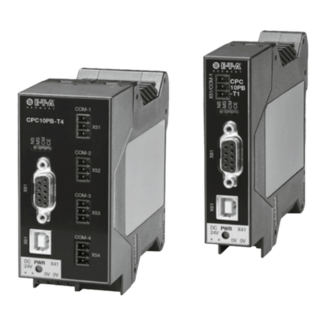
E-T-A Control Plex CPC10PB-T1 User manual
E-T-A
E-T-A ControlPlex CPC10PB User manual

