Novus N480 User manual

N480
OUT
OPERATING MANUAL

N480
2
ÍNDICE
1. installation....................................................................................................................................3
1.1 panel assembly .................................................................................................................................................3
1.2 electrical connections.........................................................................................................................................3
2. specifications................................................................................................................................3
2.1 general..............................................................................................................................................................3
2.2 temperature sensor input...................................................................................................................................3
2.3 power................................................................................................................................................................3
2.4 control output.....................................................................................................................................................3
2.5 alarm outputs.....................................................................................................................................................4
3. configuration and operation..........................................................................................................4
3.1 parameters flow chart ........................................................................................................................................4
3.2 operation level...................................................................................................................................................4
3.3 tuning and alarms level ......................................................................................................................................4
3.4 configuration level..............................................................................................................................................5
3.5 calibration level..................................................................................................................................................5
4. ramp to soak function characteristics ...........................................................................................6
5. problems with the controller..........................................................................................................6
5.1 electronic serial number visualization .................................................................................................................6
6. alarm functions.............................................................................................................................6
6.1 alarm initial blocking ..........................................................................................................................................7
7. pid auto tune ................................................................................................................................7

N480
3
1. INSTALLATION
1.1 PANEL ASSEMBLY
The controller should be installed in a panel cut out as specified in item 2.1. First remove the mounting clamp and insert the
controller into the panel cut out. Place the unit into the panel cut-out and slide the mounting clamp from the rear to a firm
grip at the panel.
The internal circuitry can be fully removed from the housing without disconnecting any wiring. By using the thumb just
press the tab in the lower part of the front panel, grab firmly the front panel and pull out the circuitry from the housing.
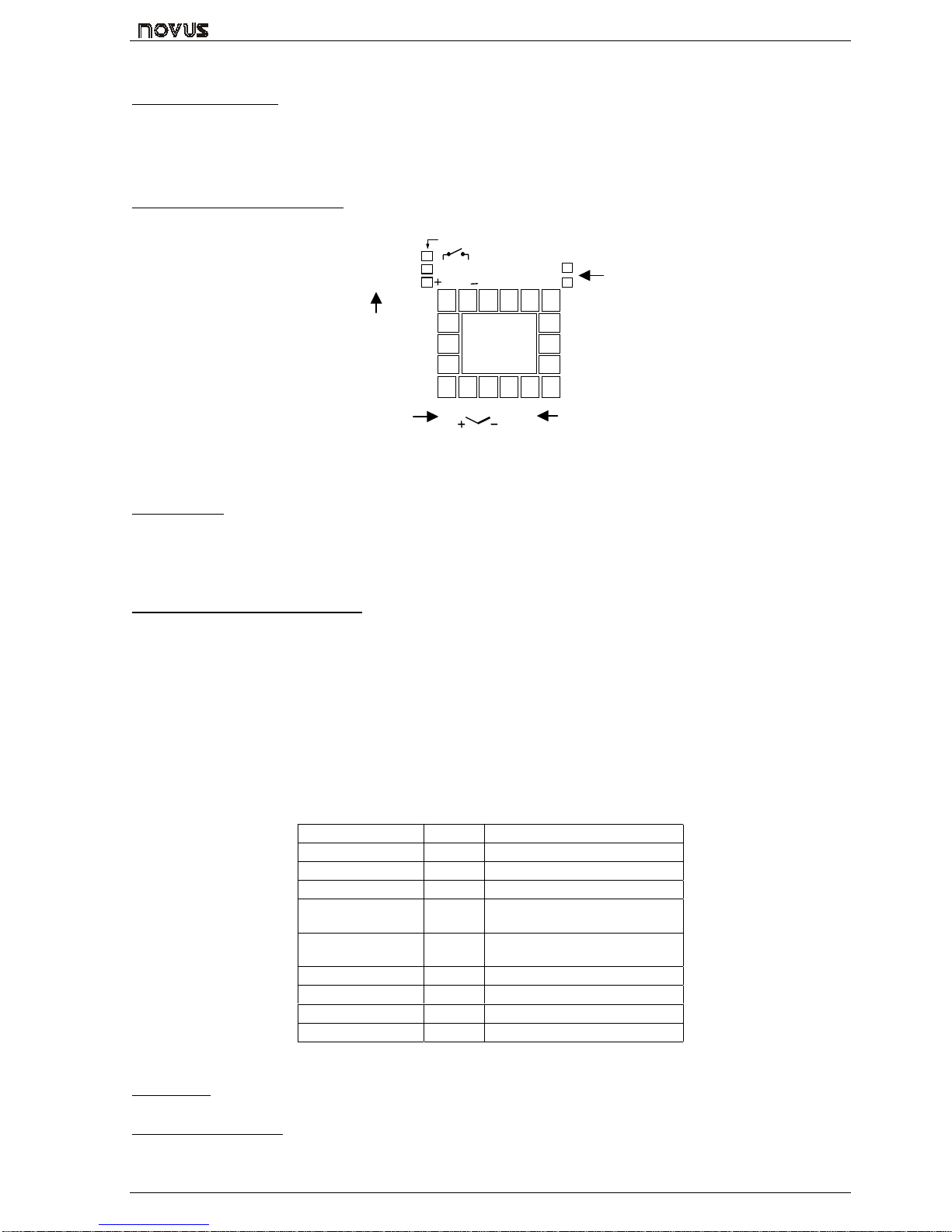
1.2 ELECTRICAL CONNECTIONS
Figure 1 shows the electrical terminals of the controller.
123456
78910 11 12
13
14
15 18
17
16
POWER
AC/DC
15-30V
85-264V
SENSOR INPUT AL2
OUT-B
OUT-A
PULSE
4-20mA
RELAY OUTPUT
PULSE OUTPUT
4-20mA OUTPUT POWER
ALARM 2
CONTROL
OUTPUT
OR ALARME 1
Figure 1 - Electrical connections
2. SPECIFICATIONS
2.1 GENERAL
•Dimensions: 48x48x106mm (1/16 DIN). Panel cut-out: 45,5x45,5mm
•Weight: 140g (1 relay), 160g (3 relays)
•Power: 85 to 264Vdc/ac, 50/60Hz, 3VA max. Optional: 15 to 30Vdc/ac
•Operation: 0 to 55°C, humidity 20 to 85%
2.2 TEMPERATURE SENSOR INPUT
•Pt100: 3-wire connection. Excitation current: 170µA
•Thermocouple input impedance: 10MΩ
•A/D converter resolution: 15000 steps
•Sampling rate: 10 measurements per second
•Auto zero and auto range
•Accuracy: 0.2% of full scale for Pt100 and 0.25% of full scale ±1°C for T/C
Thermocouples are connected to terminals 8 and 9 with positive in terminal 8.
Pt100 sensors are connected to terminals 7, 8 and 9, as indicated in figure 1. For full compensation of cable resistance
only cables with equal wire electrical resistance should be used.
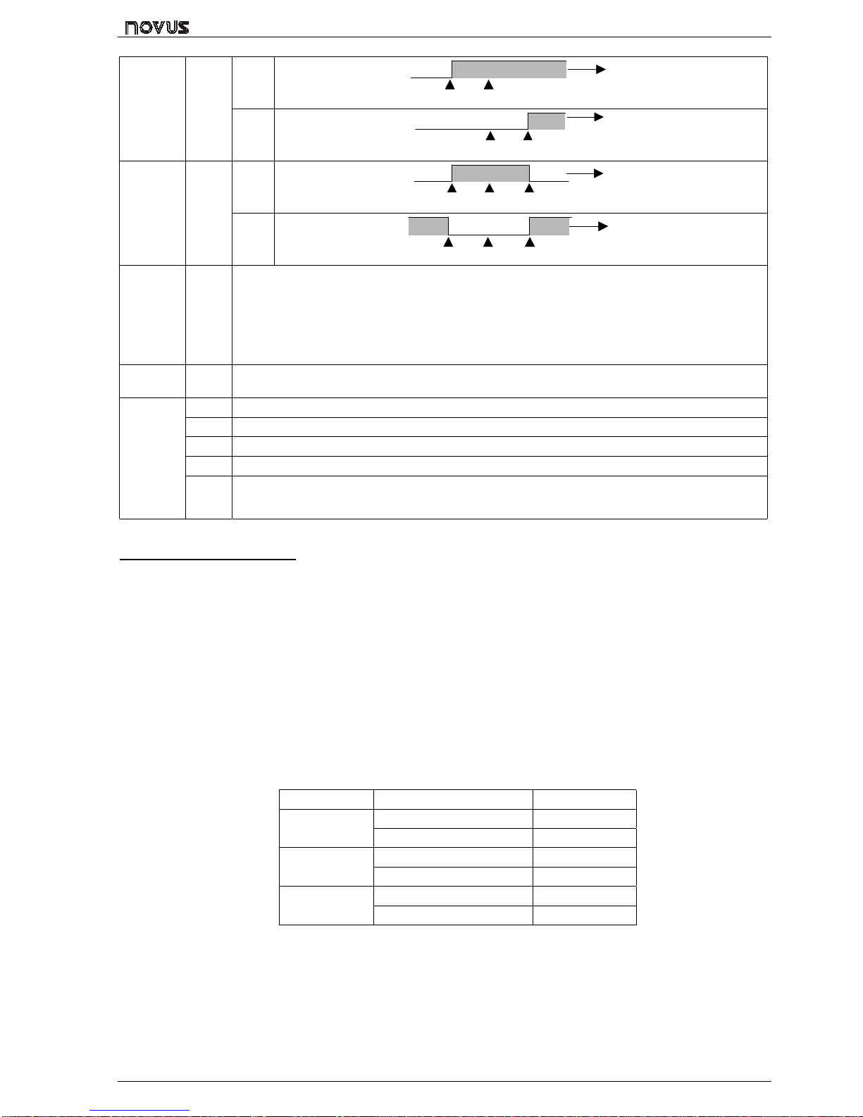
Table 1 shows the sensor types accepted and their respective codes. via keyboard.
TIPO CÓDIGO FAIXA
J0-50 a 760°C (-58 a 1400°F)
K1-90 a 1370°C (-130 a 2498°F)
S20 a 1760°C (32 a 3200°F)
Pt100 (Resolução
0,1°C) 3-199.9 a 530.0°C (-199.9 a
986.0°F)
Pt100 (Resolução
1°C) 4-200 a 530°C (-328 a 986°F)
T5-100 a 400 °C (-148 a 752°F)
E6-30 a 720°C (-22 a 1328°F)
N7-90 a 1300°C (-130 a 2372°F)
R80 a 1760°C (32 a 3200°F)
Table 1 - Sensor types, codes and ranges
2.3 POWER
Mains power is connected to terminals 5 and 6. Check the upper side of the housing for proper power indication.
2.4 CONTROL OUTPUT
•Relay output: SPST (U type) relay. Maximum current 3A/250Vac.
•Voltage pulse output: 5Vdc/20mA

N480
4
Both outputs are available in the basic model and the desired main control output is user selected via keyboard (refer to “
Cntr
CntrCntr
Cntr “ prompt). The remaining output can then be used as an alarm output.
In case of sensor break or failure an error "Erro
ErroErro
Erro"message is displayed and the control output is turned off.
2.5 ALARM OUTPUTS
•Alarm Output 1: SPST relay 3A/250Vac or 5Vdc/20mA pulse
•Alarm Output 2: SPST relay 3A/250Vca (optional)
3. CONFIGURATION AND OPERATION
Prior to first operation the controller should be fully configured. The user must set basic parameters as temperature type
(“TYPE
TYPETYPE
TYPE”), the desired control set point (“ SP
SPSP
SP “), the alarms set points (“SPA1
SPA1SPA1
SPA1” and “SPA2
SPA2SPA2
SPA2”), etc.
3.1 PARAMETERS FLOW CHART
The programming parameters are organized in 4 different sets or levels:
•Operation level
•Alarms and tuning level
•Configuration level
•Calibration level
At power up the controller displays a prompt at the Operation Level and remains in this level while under normal operation.
The other levels are only accessed when a change of parameters is necessary (except for Set Point change). To reach
these other parameters the user must keep the INDEX Key ( ) pressed for about three seconds. After this time the
controller will show the first parameter of the next level. By keeping the INDEX key pressed for another 3 seconds the next
level will be accessed.
Release the key when the desired level is reached. Press once the to go to the next prompt in the samelevel.
When a parameter is shown the display will alternate its name and value. The value can then be changed by pressing the
or key.
After the last parameter in one level is reached the controller returnsto operation level and the display will indicate the
measured temperature.
The display will also go back to the measured temperature whenever the display is inactive for 20 seconds or more.
When a parameter value is changed via keyboard the controller will only accept the new value after the user presses the
INDEX key to go to next prompt or if the keyboard is left inactive for 20 seconds.
For disabling the keyboard, move the internal strap to the position KEY DISABLE. All parameters will be protected, accept
the SP parameter.
KEY
DISABLE
KEY
DISABLE
F
igure 2 – Strap in normal operating
position (enabled)
Figura 3 – Strap position for inhibiting the
keyboard
3.2 OPERATION LEVEL
TEMPERATURE
INDICATION
END
SP
Set Point
TEMPERATURE measured by the sensor.
At power up, the upper display shows the process temperature value. It also shows the messages
described in chapter 5 of this manual.
The lower displays shows the set point value which is the temperature value desired for the process.
rAte
rAtE
TEMPERATURE RATE OF RISE: The user defines the rate of temperature rise from the starting
temperature to the value set in “ SP
SPSP
SP ”.
Rate is defined in °C / minute.
T Sp
time for
soak
TIME FOR SOAK: Time in minutes which the temperature will remain at the selected “ SP
SPSP
SP “. Refer to
item 4.
Rvn
run
RUN: At this prompt the user sets the control output and alarms to active or to inactive.
0
00
0- inactive outputs; 1
11
1- active outputs;
3.3 TUNING AND ALARMS LEVEL
Atvn
Auto tuneAUTO-TUNE: Activates the auto-tuning of PID parameters.
0
00
0- Auto-tune is off;
1
11
1- Auto-tune is on;
Pb
Proportional
band
PROPORTIONAL BAND: percentage of maximum input span.
When set ot zero (0), control action is ON/OFF.
Ir
integral rate INTEGRAL RATE: Integral time constant in repetitions per minute (Reset). This constant is not used
when controller is set to ON/OFF action (Pb=0).

N480
5
Dt
derivative
time
DERIVATIVE TIME: Derivative time constant in seconds. This constant is not used when controller is
set to ON/OFF action (Pb=0).
(t
Cycle time CYCLE TIME: PulseWidth Modulation (PWM) period in seconds. This term is not used when controller
is set to ON/OFF action (Pb=0).
KySt
HYSterisis CONTROL HYSTERESIS: Is the hysteresis for ON/OFF control (set in temperature units).
This parameter is only used when the controller is in ON/OFF mode (Pb=0).
A1SP
SP Alarm 1SETPOINT for Alarm 1: Triping point for alarm 1
A2SP
SP Alarm 2SETPOINT for Alarm 2: Triping point for alarm 2
3.4 CONFIGURATION LEVEL
Type
tYPE 0
00
0- Thermocouple type J 3
33
3- Pt100 with 0.1° resolution
1
11
1- Thermocouple type K 4
44
4- Pt100 with 1° resolution
2
22
2- Thermocouple type S
Type
tYPE
INPUT TYPE: Selects the input sensor type to be connected to the controller. This is the first
parameter to be set.
0
00
0- Thermocouple type J;5
55
5- Thermocouple type T;
1
11
1- Thermocouple type K;6
66
6- Thermocouple type E;
2
22
2– Thermocouple type S;7
77
7- Termopar tipo N;
3
33
3- Pt100 with 0,1° resolution; 8
88
8- Termopar tipo R;
4
44
4- Pt100 with 1° resolution;
Vnit
unit
TEMPERATURE UNIT: Selects display indication for degrees Celsius or Farenheit.
0
00
0- degrees Celsius ( °C ); 1
11
1- degrees Farenheit ( °F );
A(t
ACtion CONTROL ACTION:
0
00
0- reverse action. Generally used for heating.
1
11
1- direct action. Generally used for cooling.
(ntr
Control
CONTROL OUTPUT:
0
00
0- Sets control output to terminals OUT A.
1
11
1- Sets control output to terminals OUT B.
As control output is defined to terminals OUT A, alarm output is automatically set to OUT B.
If control output is defined to OUT B alarm 1 will then be automatically set to OUT A.
spll
SP Low Limit
SET POINT LOW LIMIT: sets the lower range for SV
spKl
SP High Limit
SET POINT HIGH LIMIT: Sets the upper range for SV.
A1fv
Alarm 1 Function
FUNCTION OF ALARM 1: Refer to table 2 for function description and respective codes to set at this
prompt.
A2fv
Alarm 2 Function
FUNCTION OF ALARM 2: Refer to table 2 for function description and respective codes to set at this
prompt.
Aiky
A2ky
Alarm HYsteresis
ALARM 1 AND ALARM 2 HYSTERESIS: Defines the differential range between the PV value at
which the alarm is turned on and the value at which it is turned off (in engineering units).
3.5 CALIBRATION LEVEL
A T E N T I O N
These parameters are used to calibrate the temperature measurement and should only be dealt with by experienced and well equipped personnel.
Inl(
Input Low
Calibration
SENSOR OFFSET CALIBRATION. Sets the temperature sensor low calibration (offset). The display
shows only the corrected temperature and not the offset added. A signal simulator should be used to
inject a low value signal to properly adjust the offset.
InK(
Input High
Calibration
INPUT HIGH CALIBRATION. Sets the sensor input circuit gain or high calibration.
A signal simulator should be used to inject a high value signal to properly adjust the offset.
(j L
Cold Junction Low
Calibration
COLD JUNCTION OFFSET CALIBRATION: Sets the cold junction offset calibration. A good
thermometer or a temperature simulator should be used to properly adjust this parameter.

N480
6
4. RAMP TO SOAK FUNCTION CHARACTERISTICS
This function makes the process temperature rise gradually from the starting point (present PV) to the temperature value
set in “ SP
SPSP
SP “ (Ramp).
The user defines the rate of rise in degrees per minute at the “rAtE
rAtErAtE
rAtE” prompt.
When SP is reached the temperature is leveled at this point for 1 to 9999 minutes as programmed at the “ t SP
t SPt SP
t SP ” prompt.
Setting 0(zero) at “ t SP
t SPt SP
t SP ” defines an infinite length soak profile.
To disable the ramp function Set 0.0 at the “rAtE
rAtErAtE
rAtE” prompt. To disable the soak function set 1at the “ t SP
t SPt SP
t SP ” prompt (thus
making a 1 minute soak) and the control output will go off in 1 minute. To restart control set 1 at the “ rvn
rvnrvn
rvn ” prompt.
After a power failure the controller will resume ramp to soak execution at the equivalent previous ramp point. If the proces
temperature is the same as the SP (no temperature drop) the controller will repeat the soak segment.
SoakTemperature
PV
Ramp
Time
SP
Figure 2 - Ramp to Soak Function
5. PROBLEMS WITH THE CONTROLLER
Connection and configuration errors state for most of the problems in using the controller. A final revision of parameters will
save time and further losses.
Error messages are displayed to help the user to identify possible problems.
: Process temperature is below the selected sensor range.
: Process temperature is above the selected sensor range
: Controller or sensor error. Example:
•Broken thermocouple or Pt100.
•Pt100 badly connected, short-circuited or high cable resistance.
5.1 ELECTRONIC SERIAL NUMBER VISUALIZATION
To read the 8-digit serial number go to the Operation Level and press the key for 3 seconds. The display will show the
first 4 digits. Keep the key pressed for 3 seconds and the display will show the last 4 digits.
FIRST 4 DIGITS
SERIAL NUMBER
LAST 4 DIGITS
When powering the unit the display will show the software version for a few seconds.
6. ALARM FUNCTIONS
Low and high alarms are used to signal minimum and maximum temperature values as programmed in the “SPA1
SPA1SPA1
SPA1” ande
“SPA2
SPA2SPA2
SPA2” prompts.
Differential alarms are used to indicate deviations from the desired setpoint (SP) temperature. These deviations are
programmed at the “SPA1
SPA1SPA1
SPA1” and “SPA2
SPA2SPA2
SPA2” prompts.
Error alarm shows sensor defects or not properly connected.
Alarm hysteresis is fixed and factory set as described below:
•Pt100: 1.1ºC
•Thermocouples: type J: 1.3ºC; types K and S: 2.3ºC
Table 2 shows each alarm function operation with their respective code. Alarm 1 is used as an example.
TYPE CODE ACTION
LOW 0
SPA1
Alarm ON TEMPERATURE
HIGH 1
SPA1
Alarm ON TEMPERATURE
LOW
differenti
al
2SPA1
Negati
ve SP + SPA1SP
Alarm ON TEMPERATURE
SPA1
Positi
ve SP + SPA1 SP
Alarm
ON TEMPERATURE

N480
7
HIGH
differenti
al
3SPA1
Negati
ve SP + SPA1 SP
Alarm ON TEMPERATURE
SPA1
Positi
ve SP + SPA1SP
Alarm
ON TEMPERATURE
differenti
al or
deviation
4SPA1
Negati
ve SP + SPA1SP - SPA1 SP
Alarm ON TEMPERATURE
SPA1
Positi
ve SP + SPA1SP - SPA1 SP
Alarm
ON
Alarm
ON TEMPERATURE
Input
sensor
error or
heater
break
detection
5Alarm is ON whenever:
•Temperature is below/above selected range;
•Termocouple or Pt100 is broken;
•Pt100 is shorted;
•Pt100 is badly connected or wire impedance is too high;
•The heater resistence is broken
End of
Program
6
Activated when the programmed soak time is run out. Refer to item 4 of this manual.
7
Low limit alarm disabled at power-up
8
High limit alarm disabled at power-up
9
Differential low limit alarm disabled at power-up
10
Differential high limit alarm disabled at power-up
Alarm
Function
s
With
alarm
inhibition
at power-
up
11
Differential alarm disabled at power-up
Table 2 - Alarm functions and their identification codes
6.1 ALARM INITIAL BLOCKING
The initial blocking option inhibits the alarm from being recognized if an alarm condition is present when the controller is
first energized. The alarm will actuate only after the occurrence of a non alarm condition followed by a new occurrence for
the alarm.
7. PID AUTO TUNE
During auto tune the temperature is controlled in ON/OFF mode at the programmed Set Point (SV). Depending on the
process characteristics large oscillations above and below SV may occur and auto tuning may take several minutes to be
concluded.
The recommended procedure is as follows:
•Program a new SP close to the desired final temperature other than the present measured temperature.
•Enable the auto tune at the “Atvn
AtvnAtvn
Atvn” prompt by selecting 1.
•Set 1at the “rvn
rvnrvn
rvn” prompt.
During auto tune large oscillations will be induced around the setpoint. Make sure the process can accept these
oscillations.
If auto tuning results are not satisfactory refer to table 3 for manual fine tuning procedure.
PARAMETER RESPONSE SOLUTION
Proportional Slow Response Decrease
Band Large Oscillation Increase
Integral Slow Response Increase
Rate Large Oscillation Decrease
Derivative Slow Response or Instability Decrease
Time Large Oscillation Increase
Table 3 - Suggestions for manual tuning of PID parameters

N480
8
ISO 9001
FÁBRICA Porto Alegre:
Rua: Álvaro Chaves, 155 – Floresta
TEL: 51-3323 3600
FAX: 51-33233644
E-Mail: info@novus.com.br
FILIAL São Paulo:
Rua: José Augusto Penteado, 107 – V. Madalena
TEL: 11-3675 0366
FAX: 11-3675 0377
E-Mail: s[email protected].br
FILIAL Curitiba:
Rua: Vereador Toaldo Túlio, 2235 – sala: 4
TEL/FAX: 41-372 8476
Cel.: 41-99964524
E-Mail: pr@novus.com.br
Table of contents
Other Novus Controllers manuals
Popular Controllers manuals by other brands

Oriental motor
Oriental motor AZ series operating manual

EcoPower
EcoPower AL030W installation instructions

digitalview
digitalview ALR-1920 instructions

United CoolAir
United CoolAir VFD Installation, operation and maintenance manual

KEBCO
KEBCO COMBIVERT F6 series Instructions for use

Promise
Promise Ultra100 TX2 user manual