© EA Elektro-Automatik, Germany, 41747 Viersen, Helmholtzstr. 31-34, Tel. +49 2162 37850, Fax. +49 2162 16230
9
B模式的指示
如果 "CV"灯亮,本机可当恒压源操作。而"CC"灯则指示产
品可当恒流源操作。这两种操作可自动转换。
过载保护和电流调整
输出端有连续短路保护功能。最大输出电流可从零连续上
调至额定电流值。
远端编程输出电压和电流
通过模拟接口可从外部控制输出电压和电流,也可监控它
们的实际值。最大额定电压和电流值被标准化成10V,对
应100% 的电压或电流。
监控线尾部应焊接一电阻和电容进行终止,比如:100k和
470nF。监控输出端有短路保护,允许最大负载为1mA。
连接线应屏蔽。屏蔽线必须连到引脚10 (GND)。
15针Sub-D插头外壳接到PE,但不可连到监控线的屏蔽线
上。
电压和电流值都可通过高阻抗控制输入脚设定。
电压和电流这两个设定值可单独提供,也可以一起提供。
如果只有一个用于远程控制,另一个则桥架到电位器前面。
打开电桥,并从外部电源或外部电位器供电0-10 V,给
UPS或IPS供电,设备将自动处于远程控制状态。完成此操
作,15针Sub-D插头的3和4引脚(电压)与5和6(电流)
引脚需空着。使用外部电位器时,+参考电压脚(2脚)要
连到电位器的一边,0V参考脚(1脚)则连到它的另外一
边。电位器的滑动件需分别连到UPS 3脚(电压)和IPS 5
脚。2脚和4脚不连。
在这些对应输出脚有下列监控信号:
引脚 7 = IMON,引脚 8 = UMON
远程开/关直流输出
本机可通过控制输入脚SB(9脚)转至待机模式(输出电
压被关断)。将9脚连到12脚的+5V即可实现,比如通过继
电器。断开该连接后,输出被再次打开,并上升至预设值。
Mode indication
If the LED "CV" is lit, the unit operates as a constant volt-
age source, while the LED "CC" indicates that the unit is
operating as a constant current source. The change-over
happens automatically.
Overload protection and current regulation
The output is protected against a continuous short-circuit.
The max. output current is continuously adjustable from
zero up to the rated current.
Remote programming of output voltage and current
It is possible to control output voltage and current externally
via the analogue interface as well to monitor the actual
values externally. The maximum rated voltage and current
values are standardized to 10V, corresponding to 100%
U or I.
The end of the monitor cable should be terminated by a
resistor and a capacitor, for example 100 KOhm and 470nF.
The monitor outputs are short-circuit protected and the max.
load is 1mA. The cable should be screened. The screen
must be connected to Pin 10 (GND).
The housing of the 15-pole Sub-D plug is connected to PE
and may not be connected to the screen of the monitor
cable.
The voltage and current values can both be set via the high
impedance controle inputs.
The two set values of voltage and current can be supplie
standalone but also together. In case only one is going to
be used for remote control, the other is left bridged to the
potentiometer on the front.
By opening the bridges and supplying the 0-10 V from an
external source or external potentiometer to input UPS or
IPS the device is automatically in remote control. To do that
the connections on the supplied 15-pole plug on Pin 3 and 4
(for voltage) and Pin 5 and 6 (for current) must be opened.
When useing an external potentiometer, the + reference (pin
2) can be connected to one side of a potentiometer and the
0V reference (pin 1) to the other side of the potentiometer.
The slider of the potentiometer is then connected to either
UPS (pin 3, voltage) or IPS (pin 5, current). Pin 2 and Pin
4 are then left connected.
The monitor signals are available on the respective outputs.
pin 7 = IMON and pin 8 = UMON.
Remotely switching the DC output on/o
Through the control input SB (Pin 9) the unit can be switched
into standby mode (output voltage o). This is eected by
connecting Pin 9 to +5V Pin 12, for example through a relay
contact. After opening this connection the output is switched
on again and rises up to the preset value.
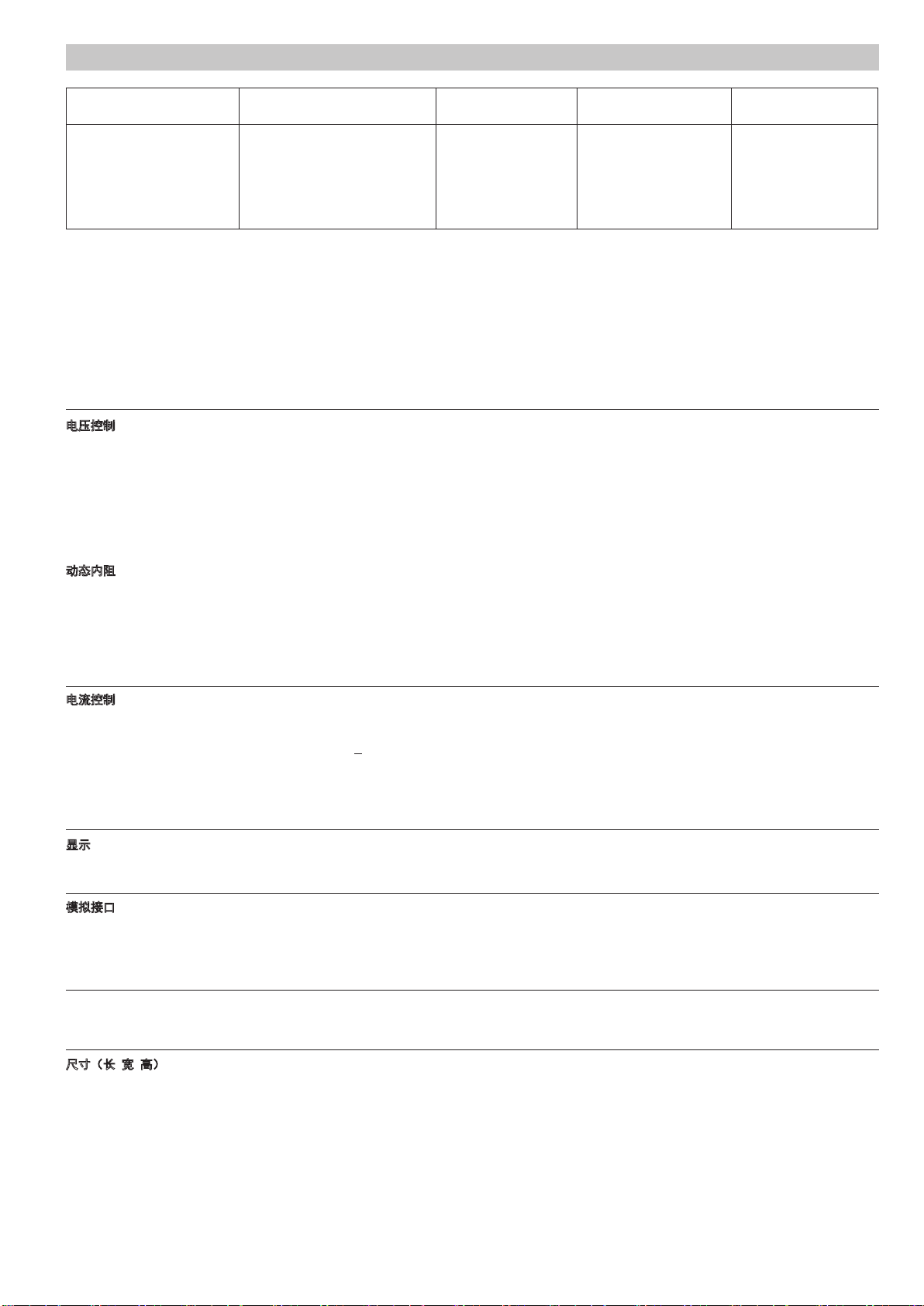
描述 / Description