EA3GCY My First Transceiver MFT-40 User manual

MFT-40 DSB Transceiver Kit Page 2
INTRODUCTION
MFT-40
The MFT-40 “My First Transceiver” is a simple, low-cost DSB (double sideband) transceiver similar to
the famous “Beach-40”, “Micro-40” by VK3YE, “Wee Willy” by VA3IUL, etc. However, the MFT has
improved both the receive and transmit characteristics, and its kit assembly puts the project within the
reach of radio circuit builders of any level.
The MFT-40 is a transceiver designed especially for new builders, for educational use in schools and for
club building projects and the like. However, it is also a very attractive assembly project for experienced
amateurs who like low power and want to get on the air with "minimalist" equipment.
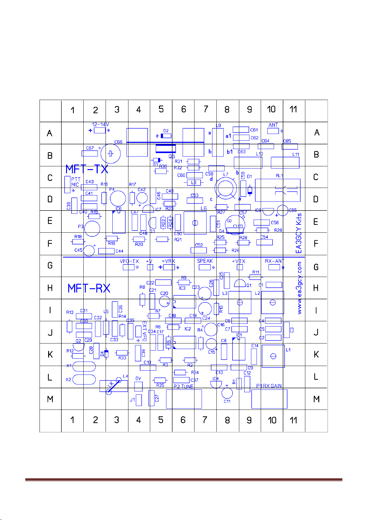
The printed circuit board (PCB) is over-sized for easy location and placement of the components. The
receiver (MFT-RX) can be assembled and put in operation independently of the transmitter, which allows
neophytes to assemble and use the receiver before beginning to work on the transmitter (MFT-TX). The
transmitter cannot operate without the receiver, since the local oscillator is built into the receiver.
The kit can be assembled on a Saturday morning, with time left in the afternoon to go out to the field with
it and make a few QRP contacts.
The MFT-40 incorporates a DC (direct conversion) receiver with a 3-stage front-end passband filter,
followed by a balanced mixer, an audio preamplifier and filter using an operational amplifier, and an
output amplifier for driving a loudspeaker. The local oscillator is based on a 7.2 MHz ceramic resonator
element that allows coverage of a part of the 40m band.
The DSB (double sideband) transmitter uses a DSB generator with input from an economical electret
condenser microphone and three stages of amplification which produce 3-4W to the antenna.
The simple circuits used make it is possible to enjoy amazing QRP contacts.
The optional “ILER-DDS” kit makes it possible to cover the entire band.
The transmitter has a robust design to withstand and work hard in the field!
There are only two controls: RX gain and tuning, which are sufficient for enjoying the pleasure of QRP!
SPECIFICATIONS
GENERAL:
Frequency coverage: ceramic resonator oscillator circuit that tunes from 7.085 to 7.165MHz approx. in
two ranges (modifiable).
Frequency control: Varicap Diode.
Antenna: 50 ohms.
Power supply: 12-14VDC, 25mA in receive (without signal), about 850mA in transmit.
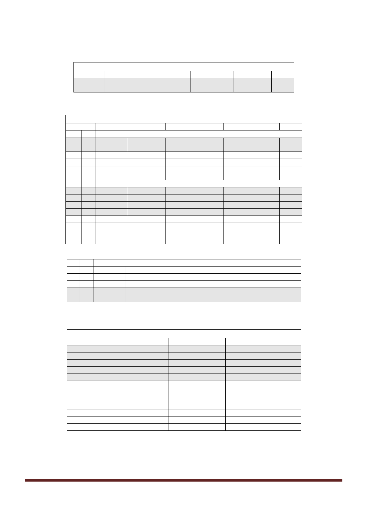
Components: 36 resistors, 2 variable resistors, 67 capacitors, 2 potentiometer (Rx gain/volume and
Tune), 5 IC's, 5 transistors, 2 inductors-chokes, 6 RF transformers, 6 diodes, 1 ceramic resonator.
Front panel controls: Tune and RX gain.
External connections: mic/ptt, speaker jack, antenna, DC input.
Circuit board dimensions: 110x130 mm.

MFT-40 DSB Transceiver Kit Page 3
TRANSMITTER:
RF output: 3W@12V, 4[email protected].
Second harmonic output: -40dB below the fundamental frequency.
Other spurious signals: all signals -45dB or better below the fundamental frequency.
Carrier suppression: better than -20dB.
T/R switching: Relay.
Microphone type: electret.
RECEIVER:
Type: DC Direct Conversion.
Front end: Triple tuned circuit.
Sensitivity: 0.5uV minimum discernible signal.
Audio Preamp and Filter
Audio output: 250mW @ 8 Ohms.
PLEASE READ ALL OF THE ASSEMBLY
INSTRUCTIONS COMPLETELY AT LEAST ONCE
BEFORE BEGINNING.
TIPS FOR FIRST TIME BUILDERS
Tools required:
- A 30w soldering iron with fine tip, small wire cutters for cutting component leads, wire strippers, long-
nose pliers, needle-nose pliers, X-Acto knife, screwdriver for M3 screws, alignment tool for adjusting IF
transformers.
- You will need a good light and a magnifying glass to see the fine print on the components and other
assembly details.
Instruments required:
- Multimeter, oscilloscope (desirable but not essential), frequency counter or HF receiver, RF power
meter, dummy load: 5W - 50 Ohms.
Soldering:
There are two important things which need to be done to insure successful operation of a kit. The first is
to put the component into the proper place on the circuit board; the second is good soldering.

MFT-40 DSB Transceiver Kit Page 4
To solder properly, you must use a high-quality solder for electronics use and the correct type of iron.
Use a small soldering iron with a fine, pointed tip. The soldering iron should be about 30 watts (if it is not
thermostatically controlled). Use only high-quality electronic type solder. NEVER use any extra flux. You
should hold the hot soldering iron in contact with both the circuit board and the component lead for about
two seconds to heat them up. Then, keeping the soldering iron in place, touch the solder at the junction
of the lead and trace and wait about two seconds or so until the solder flows between the terminal and
the trace to form a good joint. Now remove the soldering iron. The soldering iron should have been in
contact with the work piece for a total time of about 4-5 seconds. After soldering each joint, you should
clean the soldering tip, removing any excess solder. This prevents mixing in old solder and residues from
previous soldering operations.
Finding the correct component:
IC's
The component outline for the IC printed on the circuit board has a “U” shaped notch on one end,
indicating the end at which pin 1 of the IC is located. There is a similar notch on one end of the IC socket
that should be oriented over the “U” printed on the circuit board. Finally, pin 1 of the IC is also marked
with a small dimple or dot; this end of the IC should be oriented towards the notch in the IC socket or the
"U" of the component outline.
Diodes
Be careful to observe the correct polarity of the diodes. There is a black band towards one end of the
diode. This band should be oriented towards the line printed on the component outline of the circuit
board.
Electrolytic capacitors:
These must be placed with the correct polarity. The positive lead (+) is always the long lead. The
negative terminal (-) is the short lead and is marked by a stripe on the body of the capacitor. Make sure
that the positive lead of the capacitor goes through the hole marked with a "+" on the circuit board.
Coils and transformers:
You may find it convenient to wind and prepare all the coils and transformers before beginning to mount
the components. That way you won't have to stop and possibly lose concentration while winding them.
This is the part of the construction that some consider to be the most difficult. I personally find it to be
one of the easiest stages, and it can even be relaxing. Look for the most appropriate moment to do it,
and most importantly, take your time. The drawings and instructions in the manual will illustrate and
accompany you in the process.

MFT-40 DSB Transceiver Kit Page 5
PARTS LIST SORTED BY VALUE/QUANTITY
Resistor list
Qty
Value
Checked
Ref.
Identified
2
1
R31, R32
brown-black-gold
1
10
R9
brown-black-black
2
22
R1, R10
red-red-black
1
47
R29
yellow-violet-black
4
100
R6, R21, R23, R26
brown-black-brown
1
220
R33
red-red-brown
3
470
R14, R15, R28
yellow-violet-brown
6
1K
R2, R13, R20, R25, R30, R34
brown-black-red
4
4K7
R8, R19, R24, R27
yellow-violet-red
1
6K8
R22
blue-gray-red
5
10K
R3, R4, R7, R11, R18
brown-black-orange
2
56K
R16, R17
green-blue-orange
3
100K
R5, R12, R35
brown-black-yellow
2
10K
P3, P4 Trimmer 10K (103)
103 trimmer
1
1K
P1 RX-Gain Potentiometer
B 1K lin.
1
50K
P2 Tune Potentiometer
B 50K lin.
Capacitor list
Qty
Value
Checked
Ref.
Identified
2
470n
C39,C40
474 or 0.47
27
100n
C1 C8 C9 C10 C12 C13 C14 C18 C22 C25 C26 C28 C37 C38 C44 C46
104 or 0.1
C47 C49 C52 C53 C54 C58 C59 C60 C61 C62 C67
4
10n
C19, C21, C56, C57
103 or 0.01
1
2n2
C17
222, 222K, 0.0022
5
1n
C35, C41, C43, C48, C51
102 or 0.001
1
1n
1000p Polystyrene, C64
1000
2
470p
470p Polystyrene, C63, C65
470
2
330p
C32, C33
n33 or 331
4
82p
C2, C4, C6, C50
82P
6
22p
C7, C29, C30, C31, C34, C36
22P, 22pK or 22J
2
8p2
C3, C5
8P2 or 8.2
1
220uf
C66 (elec.)
220uf 25v or 35V
2
100uf
C23, C24 (elec.)
100uf 25V or 35V
7
10uf
C11, C15, C16, C20, C42, C45, C55 (elec.)
10uf 25V 35V or 63V

MFT-40 DSB Transceiver Kit Page 6
Semiconductor list
Qty
Type
Checked
Ref.
Identified
Transistors
2
BC547
Q1, Q2
BC547
1
P2222
Q3
2222
1
BD135
Q4
BD135
1
2SC2078
Q5 (heatsink + washer + mica spacer)
C2078
Integrated circuits
1
LM741
IC2
LM741CN or UA741
2
SA/NE602
IC1, IC6
SA602AN or NE602AN
1
LM386
IC3
LM386N-1
2
78L06
IC4, IC7
MC78L06
1
78L08
IC8
MC78L08
Diodes
1
1N4148
D1
4148
1
1N4001(7)
D2
1N4001 or 1N4007
1
47V
D3 Zener 47V 1W
BZX85C47 or Z47
1
9V1
D4 Zener 9V1 0.5W
9V1
1
SVC236
Varicap diode SMD
Z V
Inductor/RF Transformer/Crystal/Relay list
Qty
Value
Checked
Ref.
Identified
1
100uH
L8 Axial inductor
brown, black, brown
1
2,7uH
L5 Axial inductor
red-violet-gold
2
T37-2
L10, L11 LPF toroids
9.5 mm diam. Red
--
L4 Toroid. Tuning inductor NO USED
--
4
5u3H (3334)
L1, L2, L3, L6 shielded coils 5u3H
5u3H
2
FT37-43
L7 toroid 10t - 3t ; L9 toroid 8t+8t
9.5 mm diam. Black
1
7.200
X1
7200
-
--
X2 –not used -
1
Relays
RL1
-
Hardware
Qty
Value
Checked
Ref.
Identified
5
M3 nuts
hex nuts M3
-
4
spacers
5mm hexagonal spacer for M3 screw
-
4
M3x5 screw
5mm M3 screw
-
1
M3x10 screw
10mm M3 screw
-
1
M3 washer
M3 lock washer
-
22
pins
MIC(3), 12-14V(2), ANT(2), SPEAK(2), EXT-VFO(2), J1(2)
*VFO-TX (2) +V (1), +VRX (2),SPEAK(2) , +VTX (1), RX-ANT(2), EXT-VFO(2), J1(2)
-
1
jumper
jumper for J1
-
4
IC socket
IC’s socket 8 pin
-
1
Heatsink
RD756 Heatsink for Q5 (output transistor)
-
110cms
Copper wire
110cm enameled copper wire 0,5mm
-
1
Electret Mic
Electret Microphone Capsule
-
1
MFT PCB
110mm x 130mm MFT PCB
-
* Pins listed in small print are only placed if the receiver is built independently (without the transmitter).

MFT-40 DSB Transceiver Kit Page 7
LIST OF INDIVIDUAL COMPONENTS
The shaded rows are the receiver parts; the other rows are the components of the transmitter. The receiving block
contains the VFO and can operate independently even if the transmitter is not built; however, the transmitter needs
the receiver to work.
Resistors
Checked
Ref.
Value
Ident./Comment
Circuit section
Located
R1
22
red-red-black
RX mix
L-9/8
R2
1K
brown-black-red
Audio filter & preamp
K-6
R3
10K
brown-black-orange
Audio filter & preamp
K-5
R4
10K
brown-black-orange
Audio filter & preamp
J/K-7
R5
100K
brown-black-yellow
Audio filter & preamp
J/K-5
R6
100
brown-black-brown
Audio filter & preamp
J-5/6
R7
10K
brown-black-orange
Audio Amp
I-5
R8
4K7
yellow-violet-red
Audio Amp
H/I-4
R9
10
brown-black-black
Audio Amp
H-6
R10
22
red-red-black
Audio Amp
I-7/8
R11
10K
brown-black-orange
Rx mute
G/H-9
R12
100K
brown-black-yellow
VFO
K-1
R13
1K
brown-black-red
VFO
J-1
R14
470
yellow-violet-brown
VFO
J-3
R15
470
yellow-violet-brown
DSB Generator
E-2
R16
56K
green-blue-orange
DSB Generator
D-2
R17
56K
green-blue-orange
DSB Generator
D-4
R18
10K
brown-black-orange
Electret mic. Bias
F-1
R19
4K7
yellow-violet-red
Electret mic. Bias
F-3
R20
1K
brown-black-red
Pre Driver
F-4
R21
100
brown-black-brown
Pre Driver
F-5
R22
6K8
blue-grey-red
Pre Driver
E-5
R23
100
brown-black-brown
Pre Driver
D-5
R24
4K7
yellow-violet-red
Pre Driver
E-5
R25
1K
brown-black-red
Driver
F-8
R26
100
brown-black-brown
Driver
F-8
R27
4K7
yellow-violet-red
Driver
D-8
R28
470
yellow-violet-brown
Driver
F-9
R29
47
yellow-violet-black
Driver
E-10
R30
1K
brown-black-red
Output Amp Bias
C-5
R31
1
brown-black-gold
Output Amp
B-6/7
R32
1
brown-black-gold
Output Amp
C-6/7
R33
220
red-red-brown
VFO
K3
R34
1K
brown-black-red
VFO
L6
R35
100K
brown-black-yellow
VFO
L5
P1
1K
RX-GAIN Potentiometer
RX Antenna Input
M-10
P2
50K
TUNE Potentiometer
VFO
M-6
P3
10K
103 trimmer
Mic Gain
E-2
P4
10K
103 trimmer
DSB balance
D-3
Capacitors
Checked
Ref.
Value
Ident./Comment
Circuit section
Located
C1
100n
104 or 0.1
RX antenna Input
H-10
C2
82p
82 or 82J
Rx passband
J-10
C3
8p2
8p2 or 8.2p
Rx passband
J-11
C4
82p
82 or 82J
Rx passband
I/J-10
C5
8p2
8p2 or 8.2p
Rx passband
J-10

MFT-40 DSB Transceiver Kit Page 8
C6
82p
82 or 82J
Rx passband
J-8/9
C7
22p
22 or 22J
Rx passband
J-8/9
C8
100n
104 or 0.1
Rx Mix
K-8
C9
100n
104 or 0.1
Rx Mix
L-8/9
C10
100n
104 or 0.1
Rx Mix
L-4/5
C11
10uF
10uF electrolytic
Rx Mix
M-8
C12
100n
104 or 0.1
Rx Mix
L-9
C13
100n
104 or 0.1
Audio filter & preamp
L-8
C14
100n
104 or 0.1
Audio filter & preamp
K-9
C15
10uF
10uF electrolytic
Audio filter & preamp
K-7
C16
10uF
10uF electrolytic
Audio filter & preamp
J-7
C17
2n2
222 or 222K or .0022
Audio filter & preamp
J/K-5
C18
100n
104 or 0.1
Audio filter & preamp
I-5/6
C19
10n
103 or 0.01
Audio Amp
I-6/7
C20
10uF
10uF electrolytic
Audio Amp
I-5
C21
10n
103 or 0.01
Audio Amp
I-5
C22
100n
104 or 0.1
Audio Amp
H-5
C23
100uF
100uF electrolytic
Audio Amp
H-7
C24
100uF
100uF electrolytic
Audio Amp
I-7
C25
100n
104 or 0.1
Audio Amp
H-8
C26
100n
104 or 0.1
Audio Amp
H-7/8
C27
No used
---
VFO
M/L-4
C28
100n
104 or 0.1
VFO
K-2
C29
22p
22 or 22J
VFO
J-1/2
C30
22p
22 or 22J
VFO
J-1/2
C31
22p
22 or 22J
VFO
I-1/2
C32
330p
n33 or 331 or 331J(K)
VFO
J-2
C33
330p
n33 or 331 or 331J(K)
VFO
J-3
C34
22p
22P, 22pK or 22J
VFO out
J/K-5
C35
1n
102 or 0.001
VFO
J-4
C36
22p
22P, 22pK or 22J
VFO out
I-4
C37
100n
104 or 0.1
VFO
L-6
C38
100n
104 or 0.1
VFO
K-4
C39
470n
474 or 470K
Mic Input
D-1
C40
470n
474 or 470K
Mic Input
D-2
C41
1n
102 or 0.001
Mic Input
D-2
C42
10uF
10uF electrolytic
DSB Generator
D-4
C43
1n
102 or 0.001
Electret mic bias
C-2
C44
100n
104 or 0.1
Electret mic bias
F-2/3
C45
10uF
10uF electrolytic
Electret mic bias
F-2
C46
100n
104 or 0.1
DSB Generator
D-5
C47
100n
104 or 0.1
DSB Generator
E-4
C48
1n
102 or 0.001
Pre Driver Input
E-4
C49
100n
104 or 0.1
Pre Driver
D-5/6
C50
82p
82 or 82p or 82J
Pre Driver passband
E-6
C51
1n
102 or 0.001
Driver Input
E-7
C52
100n
104 or 0.1
Pre Driver
F-7
C53
100n
104 or 0.1
Pre Driver
D-6/7
C54
100n
104 or 0.1
Pre Driver
F-10
C55
10uF
10uF electrolytic
Output Amp Bias
D/E-10/11
C56
10n
103 or 0.01
Driver
E-9/10
C57
10n
103 or 0.01
Driver
D-9
C58
100n
104 or 0.1
Output Amp
C-7/8
C59
100n
104 or 0.1
Driver
C/D-9
C60
100n
104 or 0.1
Output Amp Bias
C-6/7
C61
100n
104 or 0.1
Output Amp Bias
A-8/9
C62
100n
104 or 0.1
Output Amp
A-8/9
C63
470p poly
470
LPF
B-8/9
C64
1000p poly
1000 or 1n
LPF
B-10
C65
470p poly
470
LPF
B-11
C66
220uF
220uF electrolytic
Relay Tx/Rx switch
B-3
C67
100n
104 or 0.1
Relay Tx/Rx switch
B-2

MFT-40 DSB Transceiver Kit Page 9
Crystals
Checked
Ref.
Frequency
Ident./Comment
Circuit section
Located
X1
7.200 ceramic resonator
VFO
K/L-1/2
X2
L-1/2
Semiconductors
Checked
Ref.
Type
Ident./Comment
Circuit section
Located
Transistors
Q1
BC547
BC547
Rx Mute
H-8/9
Q2
BC547
BC547
VFO
K-1
Q3
P2222
PN2222
Pre Diver
E-5
Q4
BD135
BD135
Driver
E-8
Q5
2SC2078
2SC2078
Output Amp
B-5
IC's
IC1
SA/NE602
SA602AN or NE602AN
Rx Mix
K-8/9
IC2
LM741
LM741CN or UA741
Audio filter & preamp
J/K-6
IC3
LM386
LM386N-1
Audio Amp
I-6
IC4
78L06
MC78L06
Rx Mix 6V supply
L-7/8
IC6
SA/NE602
SA602AN or NE602AN
DSB Generator
E-3
IC7
78L06
MC78L06
DSB Generator 6V
D-4/5
IC8
78L08
MC78L08
TX Bias supply
D/E-10
Inductors/RF Transformers/Relay
Checked
Ref.
Value/Type
Ident./Comment
Circuit section
Located
L1
KANK3334 (5u3H)
K3334 or 5u3H
Rx Mix
K-10
L2
KANK3334 (5u3H)
K3334 or 5u3H
Rx Mix
I-10
L3
KANK3334 (5u3H)
K3334 or 5u3H
Rx Mix
I-8/9
L4
Not used
--
L3
L5
2,7uH axial inductor
red-violet-gold
VFO
J-2/3
L6
KANK3334 (5u3H)
K3334 or 5u3H
TX Pre driver
E-6/7
L7
FT37-43
toroid 10t - 3t see text
Driver
C/D-8
L8
100uH axial inductor
brown-black-brown
Output Amp Bias
C-6/7
L9
FT37-43
toroid 8+8 see text
Output Amp
A/B-7/8
L10
T37-2
Turns = see text
LPF
B-9
L11
T37-2
Turns = see text
LPF
B-10/11
RL1
DV12V Relay
--
Rx/Tx switch
C/D-10/11
Diodes
D1
1N4148
4148
Rx/Tx Relay switch
C/D-9
D2
1N4007 or 4001
1N4007(1)
Output Amp Bias
A-5
D3
Zener 47V 1W
BZX85C47 or Z47
Output Amp protect
B-5
D4
Zener 9.1V
9V1
VFO
K-3
DV
SVC236
Varicap diode
VFO
M-3

MFT-40 DSB Transceiver Kit Page 10
143-QUADRANT COMPONENT LAYOUT MAP

MFT-40 DSB Transceiver Kit Page 11
ASSEMBLY
You can use the “individual parts list” or the “value/quantity parts list.” Using the “value/quantity parts list”
is the quickest way to mount components since all the circuit board components of the same value or
type can be placed one after the other. However, you will need the “individual parts list” to know how
each component is identified and its location on the circuit board. Depending on your personal
experience, you may prefer the individual parts list and feel more confident using it.
The 143-quadrant component layout map makes it very easy to find the location for all the components.
After mounting each component, it can be marked off in the “checked” column.
It is highly recommended that an inventory be taken of all the components to make sure that everything
is there and ready for assembly. Each constructor may have his/her own method of organizing the
components. One suggested method is to use a block of styrofoam packing material and poke the
components into it. The components can be sorted by type, value and size (ohms, micro-farads etc.).
RECOMMENDED ASSEMBLY SEQUENCE
Resistors and LK link.
The resistors are installed first. Mount all the resistors R1 to R35 and trimmers P3 and P4.
P1 is the Rx gain potentiometer and P2 is the Tune potentiometer, which will not be installed yet.
Refer to the parts list, and select the first resistor, R1. Bend the leads as close to the component body as
possible, and place them into the appropriate holes according to the component outline printed on the
circuit board. Be careful to avoid confusing the resistors with the axial inductors which are a bit thicker.
All of the resistors have a light-colored body and a gold band on one of the ends. Inserting the resistor
leads into the holes, push down on the body of the component so that it rests flat on the board, hold it in
place, and then slightly bend the leads to hold the resistor in place. Then turn the board over and solder
the leads to the printed circuit trace. Make sure that the resistor body lies flat on the board so that its
leads are as short as possible. Please read the notes about soldering, as poor soldering is the most
common cause for a kit failing to work for the first time. After soldering them, cut the excess length off
the component leads as close to the joint as possible. Mount the next resistor in the parts list in the same
manner and continue until all the resistors are mounted.
The values which are in decade increments can be easily confused, such as 470, 4K7 and 47K, so be
sure to verify the colors before soldering the component in place! If you are in doubt, use a multimeter to
check the resistor value.
- Bend a piece of leftover component lead and insert it into the location marked as LK on the circuit
board (located next X1-X2). This link is used as bridge in place of L4. Do not forget to intall it.

MFT-40 DSB Transceiver Kit Page 12
Axial Inductors
L5 and L8
These components look like thick-bodied resistors and the body is colored blue or green. In its interior
there is a small coil wound on a ferrite core. Refer to the parts list to select the correct component for
each location. Mount the inductors in their respective locations, as identified on the circuit board, in the
same manner as you did with the resistors, but leave a separation of 1-1.5mm from the board.
Diodes
Next mount the diodes, being careful to place them with the correct orientation. There is a band on one
end of each diode that corresponds to the component outline on the circuit board.
D1 is 1N4148; it is normally orange in color with a black band and has the type “4148” printed on the
body.
D3 is 47V zener diode. It is marked as BZX85C47 or Z47.

MFT-40 DSB Transceiver Kit Page 13
D4 is a zener diode. It is marked 9V1
D2 (bias limiter) 1N4007 or 1N4001 diode is black with a gray band. This is placed vertically as shown in
the picture (about 10-12mm high). The end with the gray band goes to the hole marked GND
DV is the varicap diode in SMD format that is already soldered.
Capacitors
There are ceramic, polystyrene (styroflex) and electrolytic capacitors. They all have their value printed on
the body. Refer to the “identified” column in the parts list.
Install and solder all the capacitors C1 to C67
When you mount them, make sure to leave the leads as short as possible.
C63, C64 and C65 are polystyrene capacitors; these are axial capacitors, but they must be placed in a
vertical position.
The values which are in decade increments can be easily confused, such as 100n and 10n, so be sure
to verify the numbers of their value before soldering them in place.
The electrolytic capacitors must be placed with the correct orientation: the LONG LEAD goes in the hole
labeled “+”and the SHORT LEAD is "-", indicated by a band containing "-" signs on the side of the
capacitor.

MFT-40 DSB Transceiver Kit Page 14
Pin "headers"
To build the complete transceiver you must place pins in: MIC(3), 12-14V(2), ANT(2), SPEAK(2), EXT-
VFO(2), J1(2)
Note: If you want to build only the RX section, then place these pins: +V(1), +VRX(2), SPEAK(2), RX-
ANT(2) EXT-VFO(2), and J1(2).
Turn the board over and insert and hold the header in place, using a “jumper” placed on the header while
you solder the pins to avoid burning your fingers. Use your other hand to hold the soldering iron and
move the board towards the solder to solder the headers in place. If you have someone available to help
you, it will be much easier!
Transistors
All of the transistors have their type printed on the component body. Place them according to the
corresponding component outline printed on the circuit board.
Transistors Q1and Q2 of the type BC547.
Q3 is a PN2222
Q4 is a BD135; the face with printed letters should be facing the top of the PCB (L7, L9 etc.)
Q5 is the output TX transistor. See picture showing the position of Q5.
The case of Q5 should be electrically isolated from the heatsink. Use the plastic washer and the mica
sheet provided with the transistor. Fasten it with the 10mm screw, nut and M3 washer. After mounting
the transistor to the heatsink, verify with a multimeter that the transistor case does not make contact with
the screw or with the heatsink. It is also recommended to apply a dab of thermal grease on both sides of
the mica sheet. Note that the screw goes through the heatsink's upper hole.

MFT-40 DSB Transceiver Kit Page 15
Integrated circuits
The component outline for the IC on the circuit board has a “U” shaped notch on one end, indicating the
end at which pin 1 of the IC is located. There is a similar notch on one end of the sockets. This should be
oriented over the "U" notch outline on the circuit board. Finally, pin 1 of the IC is marked with a small
dimple or dot; this end of the IC should be oriented towards the notch in the IC socket or the "U" on the
component outline.
Mount the sockets for IC1, IC2, IC3 and IC6 in the locations printed on the circuit board. Make sure that
the sockets lie flat against the circuit board.
Next, insert IC1, IC2, IC3 and IC6 into their respective sockets.
IMPORTANT: Make sure that the IC's are fully inserted into their sockets. A poor contact between the
socket and IC can cause malfunction of the kit.
Now, place and solder the voltage regulators IC4, IC7 (78L06) and IC8 (78L08) in their respective
locations according to the markings of the component outline on the circuit board (IC5 does not exist).

MFT-40 DSB Transceiver Kit Page 16
Resonator (or optional crystals)
Install X1resonator marked as 7200 (or 7370 optional).
Relay
Install relay RL1; it can only be mounted in one position.
Make sure that the body of the relay lies flat against the circuit board.
Shielded coils (cans)
L1, L2, L3 and L6 are shielded coils equivalent to Toko KANK3334, marked as 5u3H. They are RF
transformers for the passband filters. Make sure that they lie flat against the circuit board.
In order to solder the tabs of the shield, you will need to hold the soldering iron a little longer on the joint
or use a higher-wattage soldering iron.
LPF Toroids L10 and L11
L10 and L11 are identical. They use T37-2 cores (red toroid with 9.5mm/0.375in OD).
Cut 25cm (10”) of 0.5mm diameter enameled wire and wind sixteen (16) turns on a red toroidal T37-2
core. Spread the turns evenly around the toroid and wind them tightly so that they follow the contour of
the toroid and are as tight against the toroid as possible. The turns should be evenly distributed around
the circumference of the toroid. Leave pigtails of about 10mm (0.4”). Scrape off the enamel with a cutter
from the ends of the wire, in order to solder the toroid onto the board.
Counting the turns: Count one turn for every time the wire passes through the center of the toroid.
Important: wind the toroid exactly as shown in the pictures.
One turn more or less will affect the operation and the power output.

MFT-40 DSB Transceiver Kit Page 17
Toroidal transformer L7
L7 is an impedance matching transformer. An FT37-43 is used (black toroid with 9.5mm/0.375in OD). It
has a 10-turn primary and a 3-turn secondary.
- Take 17cm (7.5”) of 0.5mm diameter enameled wire and wind ten (10) turns on a black FT37-43
toroidal core. Spread the turns evenly around the toroid and wind them tightly so that so that they follow
the contour of the toroid and are as tight against the toroid as possible. The turns should be evenly
distributed around the circumference of the toroid. Leave pigtails of 10-20mm (0.70”).
-Now take about 8cm (3.5”) of 0.5mm diameter enameled wire and wind three (3) turns on the other
side of the toroid, spacing the turns within the space between the turns of the previous winding. Leave
pigtails of 10-20mm (0.70”).
-Before inserting them on the circuit board, use a cutter or sandpaper to scrape off the enamel from the
pigtails of the windings. Solder them in place. Mount the toroid with approximately 0.5 - 1mm distance
from the board.
- The ends of 10-turn winding to into holes “a” and “b” facing towards relay RL1. The ends of 3-turn
winding go to “c” and “d” facing towards L8 and C53 (place exactly as shown in the pictures).
Counting the turns: Count one turn for every time the wire passes through the center of the toroid.

MFT-40 DSB Transceiver Kit Page 18
IMPORTANT: Wind the toroid exactly as shown in the pictures. You must pay attention to number
of turns as well as to the direction of the winding.
Toroidal transformer L9
L9 is an impedance matching transformer with a bifilar winding. An FT37-43 is used (black toroid with
9.5mm/0.375in OD). It has 8+8 turns.
- Cut a 31-32cm (12in) long piece of 0.5mm diameter enameled wire.
- Bend the wire in half.
- Twist it so that there are about two twists per cm.
16cm (32 cm bent in half)

MFT-40 DSB Transceiver Kit Page 19
- Before beginning to wind, leave 15-20mm of wire, measured from the end of the wires to the outer
edge of the toroid. Now wind eight (8) turns on the toroid. Remember: Count one turn for every time the
wire passes through the center of the toroid.
- Spread the turns evenly around the toroid.
- Cut the ends and separate the two windings.
- Use a sharp X-Acto knife to scrape the enamel off the ends that will be soldered. The ends of the coils
that we have made need to be prepared in this manner before soldering them into the board.
- Using a multimeter in its ohm or continuity function, locate and mark the ends, identifying them as “a” -
“a1” and “b” - “b1”.
- Mount the toroid into the appropriate holes as marked on the circuit board.
Note: For greater clarity, the drawing shows one black wire and one red wire. In reality, both wires are of
the same color.

MFT-40 DSB Transceiver Kit Page 20
Jumper J1 (tuning ranges)
The Jumper J1 allows choose a part of the double varicap diode or both at the same time.
The approximate coverage (ceramic resonator 7200) is as follows:
J1 Not Placed: from 7.093 to 7.155MHz.
J1 Placed: from 7.055 to 7.130MHz.
Notes: You can use a switch on the front of the box to activate it externally (use cables as short as
possible).
Placing a capacitor in C27 or changing the values of C29 and C30 can change the frequency of
coverage. See "Changes to coverage".
Potentiometer P2 “TUNE”
Install the P2 “TUNE” potentiometer marked B50K as shown in the picture.
With this tuning control it will cover about 50-60KHz of the band.
To comfortably tune, I recommend using a control knob at least 20-30mm diameter.
RX Gain Potentiometer P1 (Volume)
Install the RX Gain potentiometer P1 as shown in the picture.
You may prefer to mount this component on the front panel, off the circuit board. There is no problem in
doing this if the wires are short.
ADJUSTMENTS AND TESTS
Preliminary adjustment
- Adjust P3 (mic gain), P4 (carrier suppression) and P1 (RF gain/volume potentiometer) to mid-position.
- Connect a speaker or headphones to the “SPEAK”pins on the circuit board.
IMPORTANT: Use a high-quality speaker box. A bad speaker will make ineffective the operation of the
transceiver.
- DO NOT yet connect a microphone.
- Apply power supply voltage (12-14V) to the “12V” header pins on the circuit board.
- Turn the volume to maximum; you should hear a hissing noise in the headphones or speaker.
Table of contents
Other EA3GCY Transceiver manuals