- 12 - - 13 -
Fault s an d sol ut io ns
EC600 0
Fault s an d sol ut io ns
EC600 0
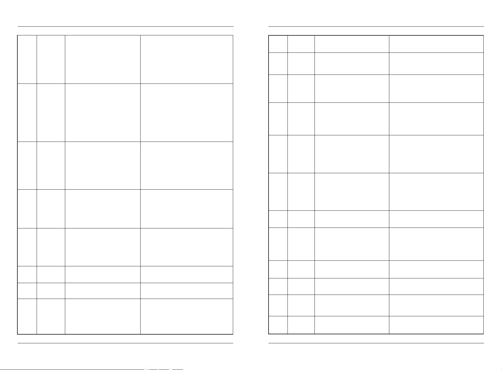
Err02
Err03
Overcurrent
during
acceleration
Overcurrent
during
deceleration
4: Manual torque boost or V/F
curve is not appropriate.
5: The input voltage is too low.
6: The startup operation is
performed on the rotating motor.
7: A sudden load is added during
acceleration.
8: The AC drive model is of too
small power class.
1: The output circuit is grounded
or short circuited.
2: Motor auto-tuning is not
performed.
3: The deceleration time is too
short.
4: The input voltage is too low.
5: A sudden load is added during
deceleration.
6: The braking unit and braking
resistor are not installed.
4: Adjust the manual torque boost or V/F
curve.
5: Adjust the voltage to the normal range.
6: Select rotational speed tracking
restart or start the motor after it stops.
7: Remove the added load.
8: Select an AC drive of higher power
class.
1: Eliminate external faults.
2: Perform the motor autotuning.
3: Increase the deceleration time.
4: Adjust the voltage to the normal range.
5: Remove the added load.
6: Install the braking unit and braking
resistor.
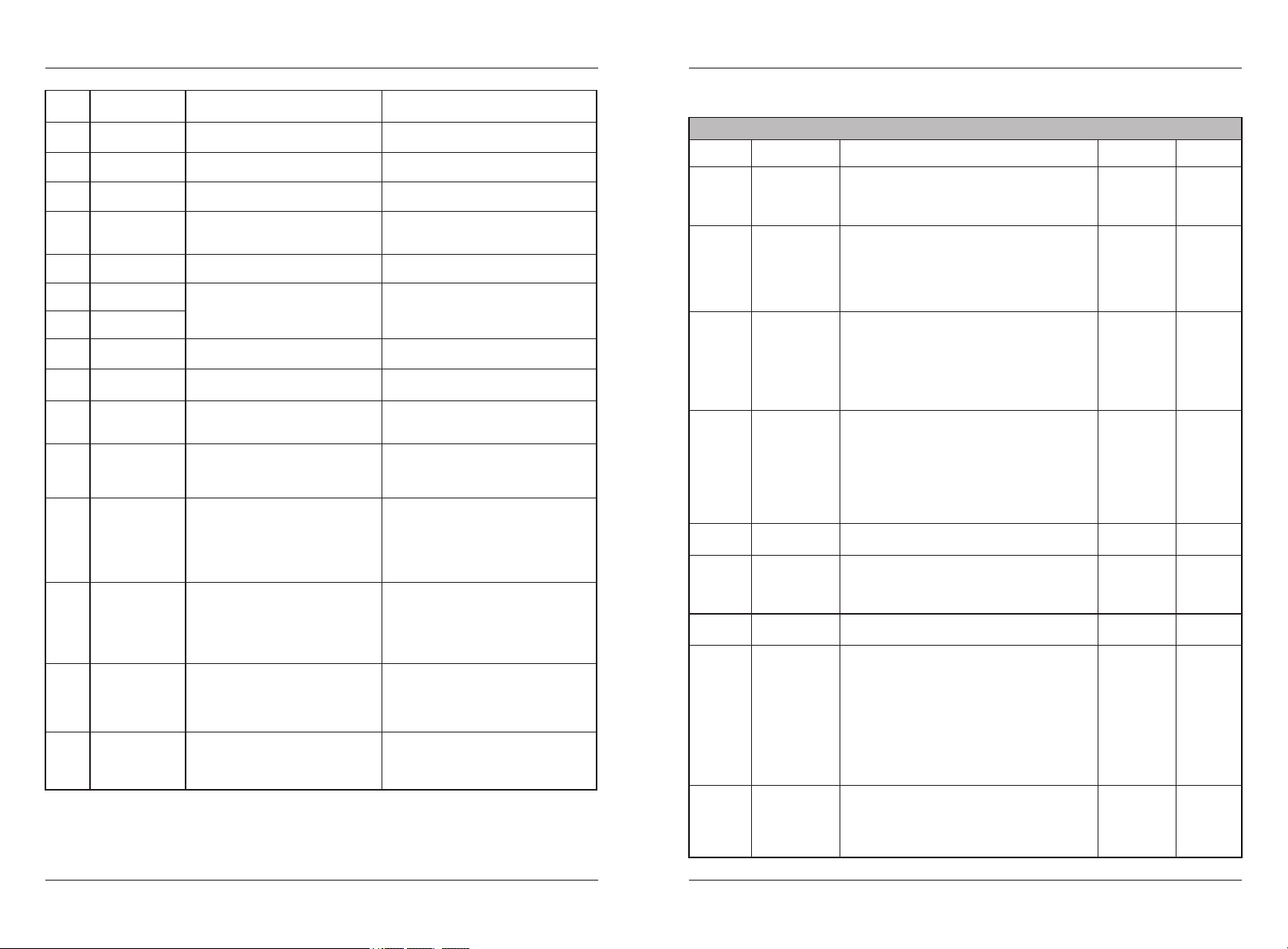
Err04
Overcurrent
at constant
speed
1: The output circuit is grounded
or short circuited.
2: Motor auto-tuning is not
performed.
3: The input voltage is too low.
4: A sudden load is added during
operation.
5: The AC drive model is of too
small power class.
1: Eliminate external faults.
2: Perform the motor autotuning.
3: Adjust the voltage to the normal range.
4: Remove the added load.
5: Select an AC drive of higher power
class.
Err05
Overvoltage
during
acceleration
1: The input voltage is too high.
2: An external force drives the
motor during acceleration.
3: The acceleration time is too
short.
4: The braking unit and braking
resistor are not installed.
1: Adjust the voltage to normal range.
2: Remove the external force or install a
braking resistor.
3: Increase the acceleration time.
4: Install the braking unit and braking
resistor.
Err06
Err07
Err08
Overvoltage
during
deceleration
Overvoltage
at constant
speed
Control
power supply
fault
1: The input voltage is too high.
2: An external force drives the
motor during deceleration.
3: The deceleration time is too
short.
4: The braking unit and braking
resistor are not installed.
1: The input voltage is too high.
2: An external force drives the
motor during running.
1: The input voltage is not
within the allowable range.
1: Adjust the voltage to normal range.
2: Remove the external force or install a
braking resistor.
3: Increase the deceleration time.
4: Install the braking unit and braking
resistor.
1: Adjust the voltage to the normal range.
2: Remove the external force or install
the braking resistor.
1: Adjust the input voltage to the
allowable range.
Err09 Undervoltage
1: Instantaneous power failure
occurs on the input power supply.
2: The AC drive's input voltage
is not within the allowable range.
3: The DC-Bus voltage is abnormal.
4: The rectifier bridge and
buffer resistor are faulty.
1: Reset the fault.
2: Adjust the voltage to the normal range.
3: Contact technical support.
4: Contact technical support.
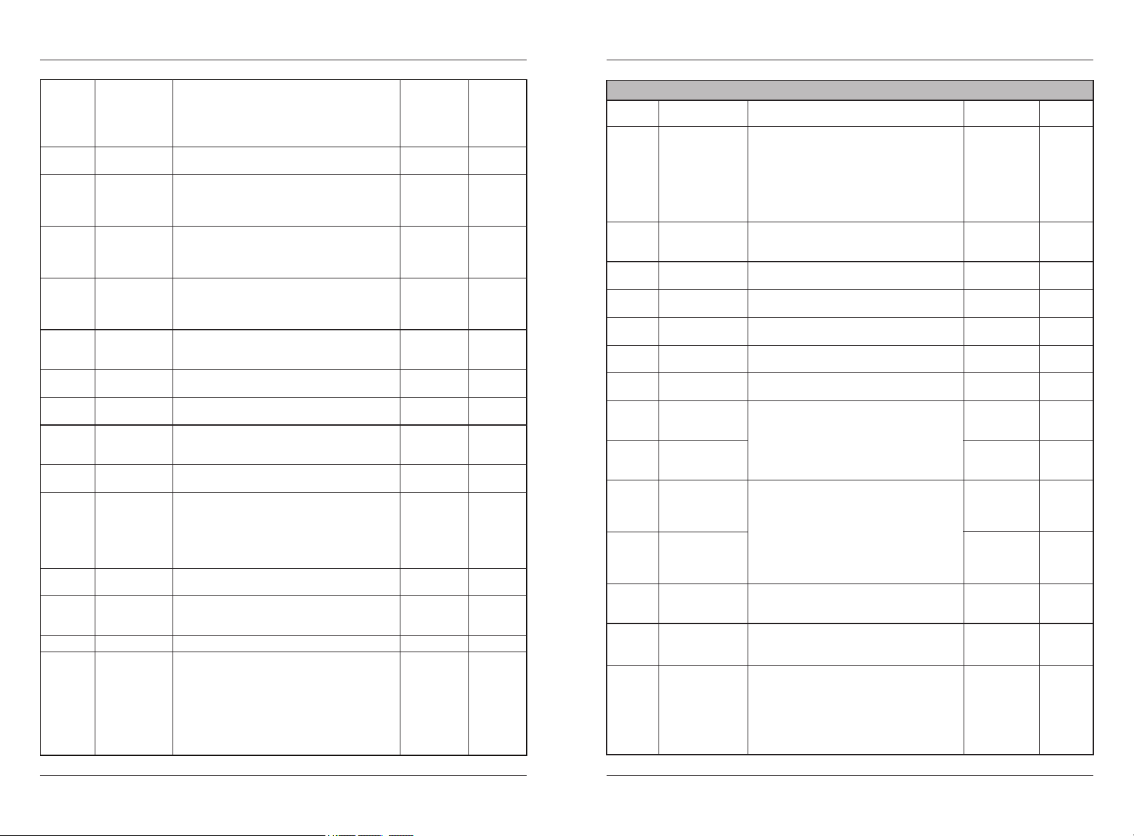
Err10
Err11
Err09
AC drive
overload
Motor
overload
Undervoltage
1: The load is too heavy or
locked rotor occurs on the motor.
2: The AC drive model is of too
small power class.
1: P9-23 is set improperly.
2: The load is too heavy or
locked rotor occurs on the motor.
3: The AC drive model is of too
small power class.
5: The drive board is faulty.
6: The main control board is
faulty.
1: Reduce the load and check the motor and
mechanical condition.
2: Select an AC drive of higher power
class.
1: Set it correctly.
2: Reduce the load and check the motor and
the mechanical condition.
3: Select an AC drive of higher power
class.
5: Contact technical support.
6: Contact technical support.
Err12 Power input
phase loss
1: The three-phase power input is
abnormal.
2: The drive board is faulty.
3: The lightening board is faulty.
4: The main control board is
faulty.
1: Eliminate external faults.
2: Seek technical support.
3: Seek technical support.
4: Seek technical support.
Err13 Power output
phase loss
1: The cable connecting the AC
drive and the motor is faulty.
2: The AC drive's three-phase
outputs are unbalanced when the
motor is running.
3: The drive board is faulty.
4: The module is faulty.
1: Eliminate external faults.
2: Check whether the motor three-phase
winding is normal.
3: Seek technical support.
4: Seek technical support.
Err14 Module
overheat
1: The ambient temperature is too
high.
2: The air filter is blocked.
3: The fan is damaged.
4: The thermally sensitive
resistor of the module is damaged.
5: The inverter module is damaged.
1: Lower the ambient temperature.
2: Clean the air filter.
3: Replace the damaged fan.
4: Replace the damaged thermally
sensitive resistor.
5: Replace the inverter module.
Err15
Err16
External
equipment
fault
Communi-
cation
fault
1: External fault signal is input
via S.
1: The host computer is in
abnormal state.
2: The communication cable is
faulty.
3: The communication parameters
in group PB are set improperly.
1:Reset the operation.
1: Check the cabling of host computer.
2: Check the communication cabling.
3: Set the communication parameters
properly.
Err17
Err18
Contactor
faul
Current
detection
fault
1: The drive board and power
supply are faulty.
2: The contactor is faulty.
1: The HALL device is faulty.
2: The drive board is faulty.
1: Replace the faulty drive board or
power supply board.
2: Replace the faulty contactor.
1: Replace the faulty HALL device.
2: Replace the faulty drive board.
Err19
Motor
auto-tuning
fault
1: The motor parameters are not
set according to the nameplate.
2: The motor auto-tuning times
out.
1: Set the motor parameters according
to the nameplate properly.
2: Check the cable connecting the AC
drive and the motor.
Err20 Encoder
fault
1: The encoder type is incorrect.
2: The cable connection of the
encoder is incorrect.
1: Set the encoder type correctly
based on the actual situation.
2: Eliminate external faults.