manuals.online logo
Brands
  1. Home
  2. •
  3. Brands
  4. •
  5. EAE
  6. •
  7. Controllers
  8. •
  9. EAE SW108 User manual

EAE SW108 User manual

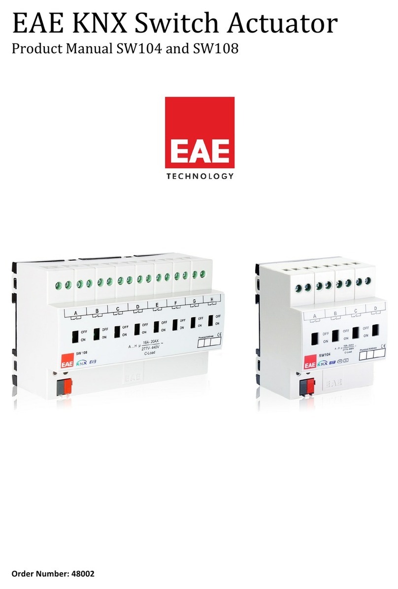
Installation Manual SW108
EAE KNX Switch Actuator 8ch SW108 IM R2.0
© EAE Technology www.eaetechnology.com
Ikitelli Org. San. Bolg. Ziya Gokalp Mah. Eski Turgut Ozal Cad.
No: 20, Zip Code: 34490 Basaksehir/Istanbul Tel:+90 212 549 97 13
Connection
1. Physical address label
2. KNX programming key
3. Red KNX programming led
4. KNX connection terminal
5. Switch position display and ON / OFF manual actuation
Description of Device
Device has eight channels which can be configured with ETS3/ETS4 or higher
version. Each channel is independent of one other. It has a separate bistable
switching relay. Also device has manual operating feature. The relay can be
switched on or off with slide switches. There is no feedback to the bus in this case.
The following function list provides;
•Staircase
•External logic
•Internal logic
•Priority
•Threshold
•Operating hour
•Sweep
Each channel of devices can choose any of these functions. The outputs are
parameterized individually via ETS3/4 or higher version. After bus voltage failure or
voltage return, relay position is selected by dependence on parameters. In “ETS
reset”, device parameters are return download configuration.
Technical Data
Protection Type
IP20
EN 60 529
Safety class
II
EN 61 140
Power
KNX
21V… 30V DC, SELV
Connection
Screw terminals
0,5…4 mm² solid and stranded wire
0,5…2,5mm² stranded wire with
ferrule
Max tight torque
0.8 Nm
KNX
Bus connection terminal
Output
Count
8
Switching
voltage
277/440V AC; 50/60 Hz
Switching
capacity
277 V AC 16A / AC 1
Fluorescent
lighting load
EN60 669-1 16 AX/250 VAC
Output life
Mechanical life
> 3 x 10⁶
Installation
35 mm
mounting rail
EN 60 715
Temperature
Ambient
Storage
-5° C + 45° C
-25° C + 55° C
Humidity
Max. Humidity
95 % non condense
Dimensions
65,5 x 143 x 89mm
Weight
0.30 kg
Box
Plastic, polycarbonate, colour grey
CE
In accordance with the EMC guideline and LV directives
Operation and Display
-Display of switch position (5)
-On/Off manual operation
The contact position shows the current situation of load circuit. It can be changed
manually ON and OFF position.
-Programming Led (3)
Red led lights up after the programming button is pressed.
Installation
The device is compatible for mounting to 35 mm DIN rail EN 60 715.
Connection
KNX connector must be connected to the KNX connection terminal. Ensure that
colour of cables are connected accurate. Load connections are made using screw
terminals. Different phase lines can be connected to load channels at the same
time. (L1, L2, L3)
Scale Drawing
Commissioning
Determination of the physical address and setting of parameters are actualized
with Engineering Tool Software (ETS3/ETS4 or higher). “.knxprod” file must be
imported to the ETS. Please check website for latest “.knxprod” file.
www.eaetechnology.com
A detailed information about parameter configuration can be found in
Product Manual of device.
Installation and commissioning of device may only be implemented by trained
electricians. The relevant standards, directives, regulations and instructions must
be observed when planning and implementing the electrical installation.
-When connecting the device make sure that the device is isolated!
-Protect the device against moisture, dirt and damage during transport, storage
and operation!
-Do not operate the device out of the specified technical data which is stated.
-The device may only be operated in closed enclosures (Distribution boards etc.)
Cleaning
If device becomes dirty, only a dry cloth can be used for cleaning. It is not suitable
to use wet cloths, caustics and solvents.
Installation Manual SW104
EAE KNX Switch Actuator 4ch SW104 R1.0
© EAE Technology www.eaetechnology.com
Ikitelli Org. San. Bolg. Ziya Gokalp Mah. Eski Turgut Ozal Cad.
No: 20, Zip Code: 34490 Basaksehir/Istanbul Tel:+90 212 549 97 13
Connection
1. Physical address label
2. KNX programming key
3. Red KNX programming led
4. KNX connection terminal
5. Switch position display and ON / OFF manual actuation
Description of Device
Device has four channels which can be configured with ETS3/ETS4 or higher version.
Each channel is independent of one other. It has a separate bistable switching relay.
Also device has manual operating feature. The relay can be switched on or off with
slide switches. There is no feedback to the bus in this case.
The following function list provides;
•Staircase
•External logic
•Internal logic
•Priority
•Threshold
•Operating hour
•Sweep
Each channel of devices can choose any of these functions. The outputs are
parameterized individually via ETS3/4 or higher version. After bus voltage failure or
voltage return, relay position is selected by dependence on parameters. In “ETS
reset”, device parameters are return download configuration.
Technical Data
Protection Type
IP20
EN 60 529
Safety class
II
EN 61 140
Power
KNX
21V… 30V DC, SELV
Connection
Screw terminals
0,5…4 mm² solid and stranded wire
0,5…2,5mm² stranded wire with
ferrule
Max tight torque
0.8 Nm
KNX
Bus connection terminal
Output
Count
4
Switching
voltage
277/440V AC; 50/60 Hz
Switching
capacity
277 V AC 16A / AC 1
Fluorescent
lighting load
EN60 669-1 16 AX/250 VAC
Output life
Mechanical life
> 3 x 10⁶
Installation
35 mm
mounting rail
EN 60 715
Temperature
Ambient
Storage
-5° C + 45° C
-25° C + 55° C
Humidity
Max. Humidity
95 % non condense
Dimensions
65,5 x 143 x 89mm
Weight
0.30 kg
Box
Plastic, polycarbonate, colour grey
CE
In accordance with the EMC guideline and LV directives
Operation and Display
-Display of switch position (5)
-On/Off manual operation
The contact position shows the current situation of load circuit. It can be changed
manually ON and OFF position.
-Programming Led (3)
Red led lights up after the programming button is pressed.
Installation
The device is compatible for mounting to 35 mm DIN rail EN 60 715.
Connection
KNX connector must be connected to the KNX connection terminal. Ensure that
colour of cables are connected accurate. Load connections are made using screw
terminals. Different phase lines can be connected to load channels at the same
time. (L1, L2, L3)
Scale Drawing
Commissioning
Determination of the physical address and setting of parameters are actualized
with Engineering Tool Software (ETS3/ETS4 or higher). “.knxprod” file must be
imported to the ETS. Please check website for latest “.knxprod” file.
www.eaetechnology.com
A detailed information about parameter configuration can be found in
Product Manual of device.
Installation and commissioning of device may only be implemented by trained
electricians. The relevant standards, directives, regulations and instructions must
be observed when planning and implementing the electrical installation.
-When connecting the device make sure that the device is isolated!
-Protect the device against moisture, dirt and damage during transport, storage and
operation!
-Do not operate the device out of the specified technical data which is stated.
-The device may only be operated in closed enclosures (Distribution boards etc.)
Cleaning
If device becomes dirty, only a dry cloth can be used for cleaning. It is not suitable
to use wet cloths, caustics and solvents.

Other EAE Controllers manuals

EAE SW104 User manual

EAE

EAE SW104 User manual

EAE UD105 User manual

EAE

EAE UD105 User manual

EAE LC100 User manual

EAE

EAE LC100 User manual

Popular Controllers manuals by other brands

Etatron eSelect-CD1 Operating	instructions and maintenance

Etatron

Etatron eSelect-CD1 Operating instructions and maintenance

iNels SA3-012M instructions

iNels

iNels SA3-012M instructions

Shimaden FP23 Series Detailed instruction manual

Shimaden

Shimaden FP23 Series Detailed instruction manual

Norac UC4+ Apache 1010 2005+ installation manual

Norac

Norac UC4+ Apache 1010 2005+ installation manual

Siemens GDB 9E Series Mounting instructions

Siemens

Siemens GDB 9E Series Mounting instructions

Agilent Technologies ETC 60 user guide

Agilent Technologies

Agilent Technologies ETC 60 user guide

Milwaukee MC720 user manual

Milwaukee

Milwaukee MC720 user manual

Pixsys DRR244 user manual

Pixsys

Pixsys DRR244 user manual

Field Controls 4615900 instructions

Field Controls

Field Controls 4615900 instructions

Eizo LMM0802 quick start guide

Eizo

Eizo LMM0802 quick start guide

Belimo LRX24-SR quick start guide

Belimo

Belimo LRX24-SR quick start guide

Daikin BRC1H61W installation manual

Daikin

Daikin BRC1H61W installation manual

OJ ETO2 instructions

OJ

OJ ETO2 instructions

Hotone Ampero quick start guide

Hotone

Hotone Ampero quick start guide

Lake Shore 805 user manual

Lake Shore

Lake Shore 805 user manual

Ecco Vantage 12 Series Installation and operation instructions

Ecco

Ecco Vantage 12 Series Installation and operation instructions

SCUDO 600 quick guide

SCUDO

SCUDO 600 quick guide

IMI NORGREN R18 Series Installation & maintenance instructions

IMI

IMI NORGREN R18 Series Installation & maintenance instructions

manuals.online logo
manuals.online logoBrands
  • About & Mission
  • Contact us
  • Privacy Policy
  • Terms and Conditions

Copyright 2025 Manuals.Online. All Rights Reserved.