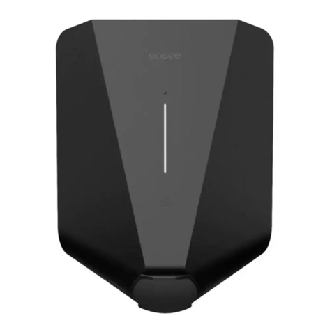
Easee Ready Assembly instructions

Easee Ready
EN Installer guide

2
Introduction
Read the Important product information guide in the
product packaging or at easee.com/manuals before
installing the product.
Installation of this product requires a mobile device with
NFC or Bluetooth support.
WARNINGS AND CAUTIONS
A Warning indicates a condition, hazard or unsafe
practice that can result in serious personal injury
or death.
A Caution indicates a condition, hazard or unsafe
practice that can result in minor personal injury or
damage to the product.
WARNING
This product shall only be installed, repaired or
serviced by an authorised electrician. All applicable
local, regional and national regulations for electrical
installations must be respected.

3
Product overview
Installation kit
Strain relief and
front cover
screws (T25)
x 5
Wall screws
(T25)
x 4
Sealing plug
x 2
Blind plug
x 3
Strain relief
x 2
Blind cover tool
x 1
Blind cover
Protects the electrical
connections from external
influences.
Backplate
For attaching and connecting to
the charging infrastructure.

4
Technical specifications
General
Dimensions 256 x 193 x 78 mm (H x W x D)
Drilling hole distance c/c 160 x 125 mm (H x W)
Backplate technical specifications
Max charging power capacity 1.4–22 kW
6 A 1 phase – 32 A 3 phase
Up to 7.36 kW at 32 A 1 phase
Up to 22 kW at 32 A 3 phase
Voltage 3x 230/400V AC (±10%)
Mains frequency 50 Hz
Protection
Degree of protection IP44
Impact resistance IK10
Installation
Installation network TN, IT or TT (detected automatically)
Installation circuit breaker Max 40 A (up to 3 chargers)
Max 80 A (up to 101 chargers)
Wire cross-section Copper wire, between 2.5 and 16 mm2.
Use the largest possible wire cross-section to make the site future-proof.
Cable diameter 8–22 mm
Terminal torque 5 Nm
Cable strip length 12 mm

5
Planning the installation
Prior to the installation, it is recommended that you
consider future charging needs, so that you can easily
expand accordingly in the future.
If several Charging Robots are connected to the same
circuit, the total current is dynamically distributed
between them. The connected Charging Robots
communicate wirelessly between each other, ensuring
the circuit is not overloaded. The maximum charging
current is set during configuration.
For an optimal result
— We always recommend a 3 phase installation if
possible, to make it future-proof.
— If possible, use the largest approved cable cross-
section (see Technical specifications).
Special notes
— Several backplates can be connected in parallel, as
each Charging Robot has its own protective device.
— If the charging infrastructure includes more than one
Charging Robot, the backplate that is configured
first becomes the master of its circuit.
— If more than 2 units are installed, the master unit
should be located in the middle of the installation (if
possible) for an optimal Easee Link communication.
— Site Key: During installation, a Site Key must
be used to assign the Charging Robots to the
correct location in the Easee Cloud. A Site Key will
automatically be generated when creating a new
charging site using the Easee Installer App or it can
be obtained by creating a new charging site at
easee.cloud.
Your house, power grid and EV
The Charging Robot automatically adapts to the power
grid, the electric car and the capacity of the electrical
installation. In the table you can see what charging
effect you can expect from your installation and
situation. The table is only meant as a guide.
CAUTION
The type of installation as well as cable cross-
sections must be determined by a qualified
electrician in accordance with valid local, regional
and national regulations for electrical systems.
Load Charging power
Ampere (A) 1 phase (kW) 3 phase (kW)1
6 1.4 4.1
8 1.8 5.5
10 2.3 6.9
13 3.0 9
16 3.7 11
20 4.6 13.8
25 5.8 17.3
32 7.4 22
1Example for 400 V TN, deviating values for other grid
types.
6
Installation
instructions 1Opening
Easee Ready
We recommend that you watch the installation
videos available on our website: easee.support.
WARNING
Always work with the power off and in
accordance with local regulations. Use
extreme caution and follow instructions
carefully.
Screw the locking screw at the bottom of the Easee
Ready.
Insert the two ends of the blind cover tool into the
two openings at the bottom of the cover.
Pull the tool until the blind cover comes loose and
remove the cover.
Lift the cover from the bottom and upwards.
1
2
3
4
2
3
4
1
1

7
Fix the backplate to a wall or structure with
sufficient load-bearing capacity using the 4 wall
screws provided in the mounting kit. Use suitable
wall plugs for mounting and observe the local
regulations for recommended installation height.
CAUTION
The installation wall must cover the entire back of
the product. If this is not possible to achieve, it is
possible to use the Easee Mount.
NOTE
If you are going to install multiple backplates, now would
be a good time to mount them as well.
1
Backplate
Mounting
2Backplate
Preparing
3
1 2
3
33
Suggested installation height
for accessibility
80–95 cm
1
1
1
1
1
x 4
1
x 1
2
x 2
3
x 3
Shorten the sealing plug to fit the cable. The hole
should be slightly smaller than the cable to ensure
a good seal.
Insert the cable through one of the 4 cable entries
and secure it to the backplate with the strain relief
provided.
Close all cable entries that are not in use with the
supplied blind plugs.
1
2
3

8
Strip each wire, exposing 12 mm of copper on each. If
the cable has flexible conductors, then you must use
ferrules on stranded wires to make the connection.
Use the correct tools to press them.
Tighten the screw terminals with a torque of 5 Nm.
NOTES
— When connecting multiple backplates in parallel,
each screw terminal serves as a coupling point
for adjacent backplates. All backplates must be
connected with the same phase sequence. External
junction boxes or flat cables can be used if it is more
convenient.
— It's recommended to follow the existing colour codes
used in the installation. Depending on national
standards, the colours of the cables can vary from
the illustrations. The illustrations in this manual
follow the IEC 60446 standard.
— Before turning on the power, make sure the wires are
properly connected and tightened.
1
2
Backplate
Wiring
4
PE
2
1
(230 V)
(3x 230/400 V)
(230 V)
(3x 230 V)
TN 1-phase
TN/TT 3-phase
IT/TT 1-phase
IT/TT 3-phase
PE N L1 L2 L3
PE N L1 – –
PE L1 L2 L3 –
PE L1 L2 – –

9
Backplate
5
Scan the QR code to download the Easee Installer
App and create your free account.
NOTE
Your phone needs to support either NFC or Bluetooth.
Select one of the two site setups in the Installer App:
Create new site: If this is a completely new charging site,
select "Create new site". Enter the installation details,
follow the on-screen instructions and return to this guide
afterwards.
1
2
Update existing site: If this site already has one or more
Charging Robots installed or if it has been created by
an operator (Easee Charge), select "Update existing site"
and search for the site address. On "Site overview", select
the circuit that you want the backplate to be part of and
select "Add another backplate". Follow the on-screen
instructions and return to this guide afterwards.
NOTE
If the charging circuits include more than one Charging
Robot, the backplate that is configured first becomes
the master unit of the charging infrastructure. To achieve
the best communication flow, the centre backplate
should be configured first.
Configuring
easee.com/installer-app

10
Hang the blind cover at the top of the backplate and
let it fall into place.
Press the bottom of the blind cover until you hear
a click.
Screw in the blind cover screw at the bottom of the
charger to secure the blind cover.
NOTE! The locking screw is necessary to secure the
cover and protect the backplate from exposure.
Your Easee Ready is now installed!
1
2
3
Blind cover
Closing
7
3
x 1
1
3
2
”CLICK!”
3

11
Cleaning
The product does not require cleaning to operate
properly. Nevertheless, if the product needs to be
cleaned for cosmetic reasons, this is possible.
— Use a damp cloth and an all-purpose household
cleaner. Avoid using strong chemicals that contain
oil or alcohol, as this will discolour the plastic.
— Do not use running water or high pressure water jets.
Repair
If your charger needs to be repaired, please contact your
Easee supplier.
Returns and complaints
Contact your distributor or Easee Customer Support
regarding the return and complaint of your product.
Customer support
Download the latest manuals, find answers to frequently
asked questions and useful documents and videos for
your product at easee.support.
Maintenance Practical details
Warranty
The device is free from material defects and is in
accordance with laws and regulations for consumer
protection in the country where the product is
purchased. All correctly installed Easee hardware is
covered by our 3 years* limited warranty. If your charger
needs to be repaired within this warranty period, please
contact your Easee supplier. Further information can be
found at easee.support.
*Some countries may have extended warranty.
Contact details
Easee ASA
Grenseveien 19
4313 Sandnes, Norway
Org. nr: 920 292 046
You can find additional contact details for your country
at easee.com.

12
The information in this document is for information purposes
only, is provided as is, and may be subject to change without
notice. Easee ASA including its subsidiaries does not accept any
liability for the correctness or completeness of the information
and illustrations, and is not liable or responsible for your
considerations, assessments, decisions or absence of such, or
other use of the information in this document.
No part of this publication may be re-published, reproduced,
transmitted or re-used in any other form, by any means or in
any form, for your own or any third-party’s use, unless otherwise
agreed with Easee or its subsidiaries in writing. Any permitted
use shall always be done in accordance with good practice and
ensure that no harm may be caused to Easee or by misleading
the consumer.
Easee and Easee products, product names, trademarks and
slogans, whether registered or not, are Easee’s intellectual
property and may not be used without Easee’s prior written
permission. All other products and services mentioned may be
trademarks or service marks of their respective owners.
July 2023 – Version 1.01
© 2023 by Easee ASA. All rights reserved.
Easee ASA
Grenseveien 19
4313 Sandnes, Norway
.easee.com
Other manuals for Ready
1
Table of contents
Other Easee Batteries Charger manuals

Easee
Easee Charging Robot Assembly instructions

Easee
Easee Equalizer User manual

Easee
Easee Equalizer Amp User guide

Easee
Easee Charge User manual

Easee
Easee One User manual

Easee
Easee Chargeberry User manual

Easee
Easee Equalizer User manual

Easee
Easee Home Troubleshooting guide

Easee
Easee Ready Troubleshooting guide

Easee
Easee Charge Lite Assembly instructions