Sterling Power USA Pro Charge Ultra User manual
Pro Charge Ultra Instruction Manual
This product requires a knowledge of both AC and DC
electrical installation. Please do not install this product unless
you are qualified to do so. All effort is made to make the
instructions as safe as possible but it is not possible to cover
all electrical safety and installation aspects. Sterling can only
assume a certain basic knowledge is held by the installer.
Only to be installed by qualified personnel.
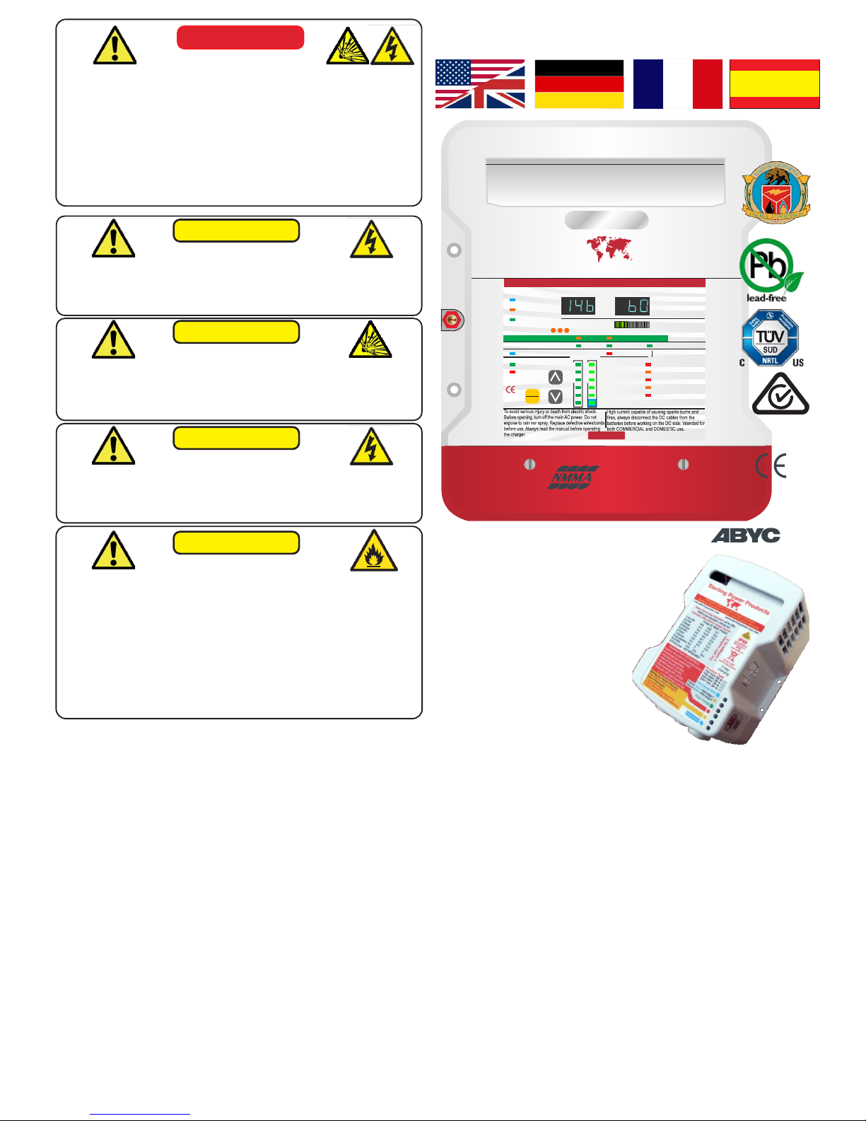
DANGER
HIGH VOLTAGE
TO AVOID SERIOUS INJURY OR DEATH FROM ELECTRICAL
SHOCK. BEFORE PERFORMING ANY ELECTRICAL WORK
ENSURE YOU TURN OFF AND REMOVE ANY AC POWER
AND CHECK VOLTAGES TO MAKE SURE THE CIRCUIT IS OFF.
DANGER
EXPLOSION HAZARD
TO AVOID SERIOUS INJURY OR DEATH MAKE CONNECTIONS
IN A WELL VENTILATED ATMOSPHERE FREE FROM
EXPLOSIVE FUMES. IT IS ADVISABLE TO WEAR SAFETY
GOGGLES WHEN WORKING NEAR BATTERIES.
DANGER
LOW VOLTAGE
TO AVOID SERIOUS INJURY OR DEATH FROM ELECTRICAL
BURNS & SPARKS ENSURE YOU DISCONNECT ANY DC
POWER AND CHECK VOLTAGES TO MAKE SURE THE CIRCUIT
IS OFF BEFORE PERFORMING ANY ELECTRICAL WORK.
CAUTION
HIGH TEMPERATURE
HOT SURFACES - TO REDUCE RISK OF BURNS DO NOT
TOUCH THE UNIT WHEN IN SERVICE.
ONLY CHARGE THE CHEMISTRY PROFILES WHICH ARE
COVERED BY THE PRESET VALUES OF THE UNIT.
IF CUSTOM SET, VALUES MUST ADHERE TO THAT OF THE
BATTERY MANUFACTURE. GETTING THE VALUES WRONG
COULD LEAD TO GASSING AND EXPLOSION OF BATTERIES.
ONLY USE THIS CHARGER WITH LITHIUM- LiFePO4 BATTERIES
IN CONJUNCTION WITH A Battery Management System FOR
FAILURE TO FIT A B.M.S. COULD RESULT IN A FIRE.
WARNING
HIGH VOLTAGE
For Multi battery type and
voltages Complementary
addition:
Battery Chemistry Module (BCM).
Allows for multiple chemistry
charging simultaneously from
one charger (different battery
types). Also allows for 24V
charging from 12V charger.
Read page 5.
PCU Top Functions:
1) 11 preprogrammed battery curves including LiFePO4.
2) 1 custom set, can be set from charger, no need for computer.
3) 2 x digital meters for current and voltage measurement.
4) 1 x power meter to show what reserve power left on the unit.
5) Active PFC, up to 0.99 pf, ensuring efficient power conversion
6) Synchronized rectification output as opposed to diode output (+10% efficiency)
7) High voltage de-sulphation cycle.
8) New, low activity, standby mode to increase battery life.
9) Battery health program.
10) Multiple speed fan control to reduce unnecessary fan noise.
11) Primary (processor digitally controlled) and an emergency backup.
12) 32 LED information panel.
13) Internal scan and systems check.
14) Remote control.
15) Small footprint and light weight.
16) Include battery temperature sensor.
17) USA CEC listed (default setting is on, CEC can be turned off). CEC
regulation stipulates that the charger is only on when necessary. This
reduces AC power consumption and lowers operational costs, while
maintaining healthy batteries.
18) % power reduction to allow unit to work with restricted input power.
19) Conforms to A.B.Y.C. drip test. Waterproof when water is dropped directly on
to the top of the unit ( +/ - 17 degrees ) if installed correctly (vertically).
20) The printed circuit boards are conformal coated for high humidity operations.
Pro Charge ULTRA
GLOBAL AC Input & Active Power Factor Correction
Sterling Power
OK
CHARGER MODE
AC Power
Auto Temp Control
Active PFC
Multi Speed Fan
Volts Amps
AUTO CONSERVATION MODES
Fault
Absorption
Stand-by Battery Health Program
Fast Charge Float
DC Output Fault
DC Low Voltage
DC High Voltage Trip
High Charger temp trip
Check Fan
De-sulphation
1 2 3
SETUP
ENTER
CHARGE INFORMATION
Open lead acid
Sealed lead acid
A.G.M
GEL
Calcium / Custom
Lithium (LiFePO4)*
System self test Battery Type
Charger Output
0% 100%
Progressive DIGITAL software control Charger / Powerpack
High Voltage AC Low Voltage DCWARNING
www.sterling-power-usa.com
Preset 1
Preset 2
www.sterling-power.com
*Lithium must be used in conjunction
with a lithium balancing system.
Safety Certified by: TUV
Built and tested to
UL 1236 SB
CSA C22.2-107.2
RoHS
compliant
CEC
approved
To Standards:
UL 1236 SB
CSA C22.2-107.2
Tested to CE standards
EN61000-3-2 EN61000-3-3
EN55014-1 EN 55014-2
EN60335-2-29
CEC listed
RoHS
compliant
EN ISO 13297
Small Craft Directive
CEC listed
12V / 60A model, all other units pro rata.
Input voltage range 80-270V 40-70 Hz
Power Factor at 230V 0.976
Efficiency 90.4%
Full load current (110/230V) 9.8/4.6A
Total Harmonic Distortion 2.4% voltage
Total Harmonic Distortion 2.4% current
Ripple noise (R.M.S.) 14mV
Ground leakage 0.5 mA
Generator/ mains power (watts)
12V 20A approx 350W
12V 30A approx 500W
12V 40A approx 600W
12V 50A approx 750W
12V 60A approx 900W
24V 20A approx 600W
24V 30A approx 900W
36V 20A approx 900W (NOT UL / CEC LISTED)
48V 15A approx 900W (NOT UL / CEC LISTED)
voltmeter accuracy +/- 1%
Ammeter accuracy +/- 1%
GLOBAL AC Input & Active Power Factor Correction
OK
CHARGER MODE
AC Power
Auto Temp Control
Active PFC
Multi Speed Fan
Volts Amps
AUTO CONSERVATION MODES
Fault
Absorption
Stand-by Battery Health Program
Fast Charge Float
DC Output Fault
DC Low Voltage
DC High Voltage Trip
High Charger temp trip
Check Fan
De-sulphation
1 2 3
SETUP
ENTER
CHARGE INFORMATION
Open lead acid
Sealed lead acid
A.G.M
GEL
Calcium / Custom
Lithium (LiFePO4)*
System self test Battery Type
Charger Output
0% 100%
Progressive DIGITAL software control Charger / Powerpack
High Voltage AC Low Voltage DCWARNING
www.sterling-power-usa.com
Preset 1
Preset 2
www.sterling-power.com
*Lithium must be used in conjunction
with a lithium balancing system.
Safety Certified by: TUV
Built and tested to
UL 1236 SB
CSA C22.2-107.2
RoHS
compliant
CEC
approved
Pro Charge ULTRA
Sterling Power
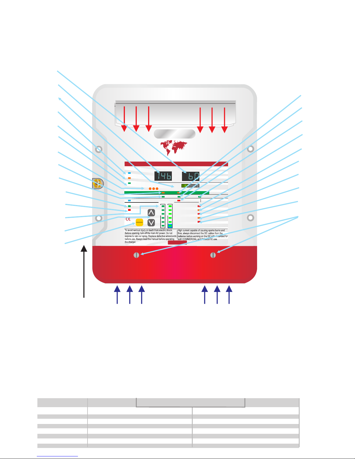
Warm air
out
Cooling
Air flow
Installation
1) Install in cool dry well ventilated space.
2) This product has a high heat tolerance and can be installed in an engine room.
3) This product is ignition protected and can be installed near the batteries.
4) Charger MUST be installed vertically to allow for convection air flow and also in the vertical position
5) The product is drip proof.
6) The product will work in any position but we cannot guarantee the drip proof aspect (only vertically).
1
2
3
4
5
6
7
8
9
10
11
12
13
14
15
16
17
18
19
20
21
22
23
24
Quick LED feature guide
1) Ammeter, shows the total current being
produced by the charger.
2) Voltmeter, showing the average voltage being
produced by the charger.
3) Power meter, shows the % power being produced
by the unit and the remaining power available.
4) AC power, shows the AC power is connected and
the product is live. LED flashes if power is available
but the unit is switched off (see on/off later) push
buttons. Setup and up arrow for 5 secs to activate.
5) Auto temp control, shows the battery temp sensor
is connected and operational. If sensor not
connected then the unit will default to a 20 deg C / 69
F charge curve.
6) Shows that the active PFC (Power Factor
Correction is on).
7) Fan speed control, varies depending on temp, 3
speeds.
8) Standby, charger power system power
requirement very low, unit on low float voltage to
prolong battery life.
9) Fast charge unit on constant current mode.
10) OK, unit operating within normal parameters
11) Fault, fatal fault, needs to be returned for repair.
12) Battery type selector, shows which battery
charger curve in operation (adjustable).
13) Buttons to select charge options (see later in
instructions) also used to switch unit off or on in
conjunction with the setup button (see 14).
Off select button press down button for 5 seconds.
On select button press up button for 5 seconds.
14) Button to enter selections. Also, use to switch
unit on/off in conjunction with the up or down button.
15) Battery health program, unit doing a 21 day de-
sulphation cycle.
16) , charger on initial charge cycle.Absorption
17) De-sulphation cycle operational. For safety
reasons only available when on open lead acid
battery type.
18) Float, unit on float charge or power pack mode,
main charge complete.
19) DC output service, output working correctly.
20) DC output low voltage warning, either batteries
are very low / more power is being taken than the
charger can supply / or the charger is defective.
21) High voltage trip, the unit is defective and
tripped itself, or a high back DC voltage has been
detected, like a wind generator reg gone defective.
22) High charger temp, if the unit is positioned in too
hot an environment and over heated, or the fans
have failed.
23) Check fans, if LED on, fans are defective.
24) Case screws to access the wiring of the product.
Battery type High Charge V Float Charge V Maintenance V High Charge V Float Charge V Maintenance V
Flooded/Open Lead acid 14.8 13.6 12.8 14.7 13.4 12.8
Sealed Lead acid 14.4 13.6 12.8 14.6 13.4 12.8
AGM Lead acid 14.3 13.3 13.0 14.6 13.6 13.0
GEL Lead acid 14.0 13.7 13.2 14.4 13.8 13.2
LiFePO4-Lithium 13.8 13.8 13.2 14.6 14.6 13.2
Calcium / Custom 15.1 13.6 13.2 Your choice see custom setup in instructions
Equalization / Desulph 15.5 15.5 15.5 15.5
Preset 1 Profiles Preset 2 Profilesx 2 all voltages for 24V unit x 3 for 36V x 4 for 48V
Fit this way up to
comply with UL
accordance and for
ABYC drip proofing
compliance.
Lithium Users Read.
This charger must not be used
to charge lithium battery cells
by itself. You cannot charge
lithium cells on their own. You
must have a lithium balancing
device in conjunction with this
charger.
DC installation (output from charger)
Choosing cable. unlike AC conductors, DC is very sensitive to voltage drop.
The longer the cable runs the larger the cable thickness needs to be. Ensure
only quality fire retardant cable is used.
DC - Fuse selection, as per the
diagram, each positive output from the
charger to the battery must be fused.
Choose a fuse that is about 20% higher
current rating than the maximum rating
of the charger, then round it up.
Remember, this fuse is primarily
protecting the cables and not the
product. E.g. a 20A charger would have
about a 25A fuse. A 60A charger about
a 75A fuse. A full range of fuses and
fuse holders are available from Sterling.
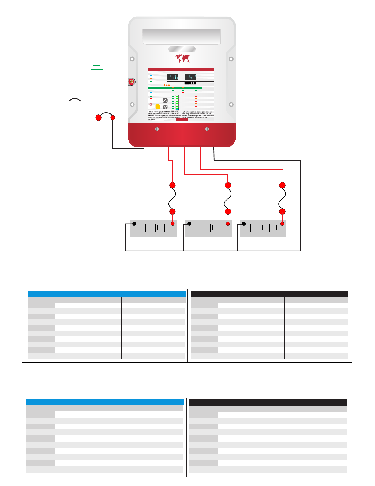
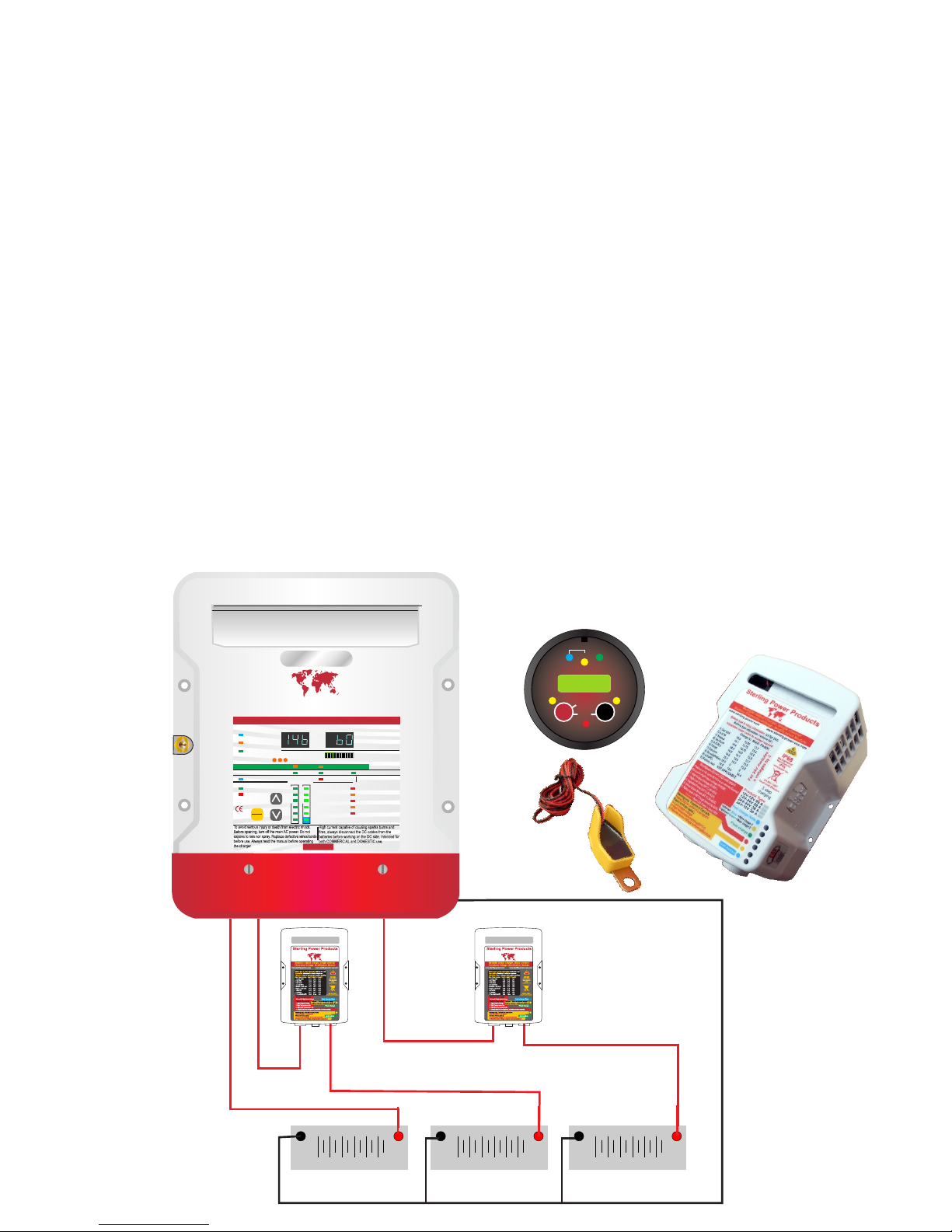
Ground / bonding / earthing.
This is extremely important and often
overlooked there are, in affect, 3 grounds.
1) The earth wire (AC input, the ground).
2) The chassis / bonding ground (going to
a vehicle body / boats bonding system,
the bolt on the side of the charger)
3) The DC negative.
In most installations all these will end up at
the same point. The AC power source
should be connect to the boat/vehicle
chassis (for safety). The chassis earth will
also go there and the DC negative should
also go there. In affect, bonding the total
system together ensuring any fault to the
chassis will blow a fuse. This could vary
for steel/aluminium boats.
+
_
12V/24V/36V/48V bank +
_
12V/24V/36V/48V bank +
_
12V/24V/36V/48V bank
AC circuit breaker
Any outputs not being used should be linked
across to one that is, this is not a requirement for
these new models but is good practice as it helps
spread loads etc.
DC fuse
20% larger
amperage than
charger output
DC fuse
20% larger
amperage than
charger output
DC fuse
20% larger
amperage than
charger output
Ground / Chassis
Boat grounding
Europe DC Charge cable size ( mm2 ) for cable length
Model 1m 2m 3m 4m 5m 6m
PCU1210 2.5 mm2 4 mm2 6 mm2 10 mm2 10 mm2 16 mm2
PCU1220 4 mm2 10 mm2 16 mm2 16 mm2 25 mm2 25 mm2
PCU1230 6 mm2 6 mm2 25 mm2 35 mm2 50 mm2 50 mm2
PCU1240 10 mm2 16 mm2 25 mm2 35 mm2 50 mm2 50 mm2
PCU1250 10 mm2 25 mm2 35 mm2 50 mm2 50 mm2 n/a
PCU1260 16 mm2 25 mm2 50 mm2 50 mm2 n/a n/a
PCU2420 4 mm2 10 mm2 16 mm2 16 mm2 25 mm2 25 mm2
PCU2430 6 mm2 6 mm2 25 mm2 35 mm2 50 mm2 50 mm2
PCU3620 4 mm2 10 mm2 16 mm2 16 mm2 25 mm2 25 mm2
PCU4815 4 mm2 10 mm2 16 mm2 16 mm2 25 mm2 25 mm2
USA DC Charge cable size ( AWG ) for cable length
Model 5 ft 10 ft 15 ft 20 ft 25 ft 30 ft
PCU1210 16 AWG 14 AWG 12 AWG 10 AWG 10 AWG 10 AWG
PCU1220 14 AWG 10 AWG 10 AWG 8 AWG 6 AWG 6 AWG
PCU1230 12 AWG 10 AWG 8 AWG 6 AWG 6 AWG 4 AWG
PCU1240 10 AWG 8 AWG 6 AWG 6 AWG 4 AWG 4 AWG
PCU1250 8 AWG 6 AWG 6 AWG 6 AWG 4 AWG 2 AWG
PCU1260 8 AWG 6 AWG 4 AWG 4 AWG 2 AWG 2 AWG
PCU2420 14 AWG 10 AWG 10 AWG 8 AWG 6 AWG 6 AWG
PCU2430 12 AWG 10 AWG 8 AWG 6 AWG 6 AWG 4 AWG
PCU3620 14 AWG 10 AWG 10 AWG 8 AWG 6 AWG 6 AWG
PCU4815 16 AWG 14 AWG 12 AWG 8 AWG 6 AWG 6 AWG
USA AC cable size ( AGM ) for cable length up to 50ft
Model 110 volt fuse/breaker 230 volt fuse/breaker
PCU1210 3 core 16 AWG 6 A 3 core 18 AWG 4 A
PCU1220 3 core 16 AWG 8 A 3 core 18 AWG 6 A
PCU1230 3 core 14 AWG 11 A 3 core 16 AWG 7 A
PCU1240 3 core 14 AWG 14 A 3 core 16 AWG 7 A
PCU1250 3 core 12 AWG 16 A 3 core 14 AWG 8 A
PCU1260 3 core 12 AWG 16 A 3 core 14 AWG 8 A
PCU2420 3 core 14 AWG 14 A 3 core 16 AWG 7 A
PCU2430 3 core 12 AWG 16 A 3 core 12 AWG 8 A
PCU3620 3 core 12 AWG 16 A 3 core 14 AWG 8 A
PCU4815 3 core 12 AWG 16 A 3 core 14 AWG 8 A
IMPORTANT
The closer to the batteries you fit the charger the better. Not only do you save
expensive cable you also get better performance from the charger. The cable
should be properly rated to 105 deg C fire resistant. Do not use solid cable or
speaker wire.
Europe AC cable size ( mm2 ) for cable length up to 15 m
Model 110 volt fuse/breaker 230 volt fuse/breaker
PCU1210 3 core 0.75 mm2 6 A 3 core 0.75 mm2 4 A
PCU1220 3 core 0.75 mm2 8 A 3 core 0.75 mm2 6 A
PCU1230 3 core 1.5 mm2 11 A 3 core 1.5 mm2 7 A
PCU1240 3 core 1.5 mm2 14 A 3 core 1.5 mm2 7 A
PCU1250 3 core 1.5 mm2 16 A 3 core 1.5 mm2 8 A
PCU1260 3 core 1.5 mm2 16 A 3 core 1.5 mm2 8 A
PCU2420 3 core 1.5 mm2 14 A 3 core 1.5 mm2 7 A
PCU2430 3 core 1.5 mm2 16 A 3 core 1.5 mm2 10 A
PCU3620 3 core 1.5 mm2 16 A 3 core 1.5 mm2 10 A
PCU4815 3 core 1.5 mm2 16 A 3 core 1.5 mm2 10 A
AC installation (input to charger)
Wiring, using ring or captive spade connections and a proper crimping tool attach the AC cables Live ( line ) Neutral and Earth / Ground. Repeat
the procedure for the breaker side of the install, support the cable every 18 inches / 0.5 m and protect from sharp edges when passing through
bulkheads and all other openings as per any standards which apply to the installation.
Pro Charge ULTRA
GLOBAL AC Input & Active Power Factor Correction
Sterling Power
OK
CHARGER MODE
AC Power
Auto Temp Control
Active PFC
Multi Speed Fan
Volts Amps
AUTO CONSERVATION MODES
Fault
Absorption
Stand-by Battery Health Program
Fast Charge Float
DC Output Fault
DC Low Voltage
DC High Voltage Trip
High Charger temp trip
Check Fan
De-sulphation
1 2 3
SETUP
ENTER
CHARGE INFORMATION
Open lead acid
Sealed lead acid
A.G.M
GEL
Calcium / Custom
Lithium (LiFePO4)*
System self test Battery Type
Charger Output
0% 100%
Progressive DIGITAL software control Charger / Powerpack
High Voltage AC Low Voltage DCWARNING
www.sterling-power-usa.com
Preset 1
Preset 2
www.sterling-power.com
*Lithium must be used in conjunction
with a lithium balancing system.
Safety Certified by: TUV
Built and tested to
UL 1236 SB
CSA C22.2-107.2
RoHS
compliant
CEC
approved
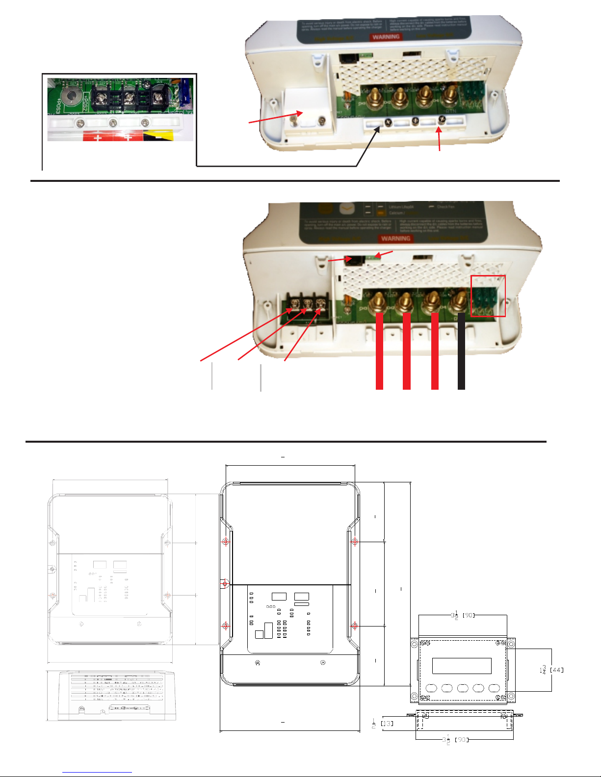
Remove the 2 screws on the bottom
of the front cover marked number 24
on the previous pages quick guide
this will reveal the main wiring area.
High Voltage
AC cover plate
and clamp DC cable clamp
Remove the 2 screws on the AC area and the 3 screws on
the DC clamps to enable the appropriate wires to
be attached. AC input 80-270V.
Ensure secure connections and correct crimping
tools are used.
DC 12V / 24V / 36V / 48V depending on unit.
Remote control
Insert the Sterling remote control
into the remote socket (telephone type)
Please note that when the remote is inserted the
front program controls on the local panel no longer
operate, control is in the remote. Remove the
remote to use local controls.
Battery Temperature sensor
Connect the battery temp
sensor to the position
as shown, connect the
sensor end to the negative stud
terminal on one of the batteries
which you think will be in the hottest environment.
When the temp. drops the charging voltage goes up incrementally.
When the temp. increases the charging voltage goes down incrementally.
Remote control
Live Neutral Earth ( European )
Live Neutral Ground ( USA )
1 2 3 Common Negative
red red red Black (Europe) Yellow (USA)
Pos terminals on
3 x battery banks
ى5
8[93]
51
8[130]35
8[93]
73
4 [198]
81
2 [215]
123
8[315]
ProMariner
Pro Nautic iQ
12-60
198 mm 7 3/4 inch
85 mm
3 3/8 inch
90 mm
3 1/2 inch
260 mm
10 1/4 inch
85 mm
3 3/8 inch
215 mm
8 ½ inch
90 mm
3 ½ inch
44 mm
1 3/4 inch
dimensions
in inches
and ( mm )
12V 10-40A
24V 20A
12V 50-60A
24V 30A
36V 20A
48V 15A
Battery temperature sensor connection
AFUSES
DC
Cut out
90 x 62 mm
PCU 12V / 30-60A &
24V 20-30A and 36V / 48V
have bolt terminals as depicted
above, rather than screw.
PCU 12V 10A & 20A models have ring
terminal screw connectors as depicted above.
N.B. the 10A model has only 2 outputs, all
other models have 3 outputs.
Earth /chassis
boats bonding
+
_
12V Sealed engine
starter Battery bank
+
_
12V LiFePO4 Lithium
Main Battery bank
+
_
24V Bow thruster
Battery bank AGM
Pro Charge ULTRA
Sterling Power
(Optional) Battery Chemistry Module
Battery Charger Chemistry Modification Module
Another great idea from Sterling. Patent Pending: GB1204145.5
What was the issue which led to the invention of this device?
A lot of new installations on modern boats require different chemistry and
even different voltage levels. For instance, you may have a 12V charger
but a 24V bow thruster or vice versa. You may also have an open lead acid
battery banks and a Lithium. This causes impossible challenges for a
standard battery charger or you may simply have one battery bank a long
way from another bank requiring very expensive cable runs to prevent
voltage drop, ( no longer a problem with the BCM ).
The solution
The new Sterling Battery Chemistry module has a unique approach to solving
this problem. We effectively place in a box a voltage booster and the output
stage from a digital charger. This means that the new device can be added to
any of the output terminals of our Pro Charge Ultra (or can be used as an add
on to most other competitor companies multiple output charger). This will
allow the main 3 (or more) output charger to be set at the lower chemistry
voltage for the likes of Gel (14.1V absorption), then, by adding the new Sterling
Multi chemistry module to one of the outputs (must be connected to an output of
a current limiting charger and cannot be connected direct to a battery. One can
adjust that output to a totally different charging chemistry profile. The output
voltage and charging curves are independent of the charger’s input voltage.
This enables a totally different chemistry to be selected. This gives all the
advantages of the multi chemistry charger without the huge extra cost, and can
be simply retrospectively fitted to any multi output battery charger (within the
limitations of the product).
Advantages of this product
1) Easy to install.
2) Fits our products and most of our competitors multiple output chargers.
or converts a single output charger into a multiple output charger.
3) 12-12V, 12-24V, 24-24V and 24-12V models.
4) 8 selectable independent latest battery chemistries to chose from and a de-
sulphation cycle, also LiFePO4 cycle .
5) Battery temperature compensation and high battery temperature trip.
6) Remote battery sense compensate for cable voltage drop.
7) 6 LEDs projecting over 20 individual charge and warning information
events.
8) Fail safe, reverts to basic charge function - about 1V less in event of a
failure. Product can be replaced / repaired at convenience.
9) High battery temperature "daisy chain" trip ( optional ). This allows every
battery to be monitored and the unit can be switched off in the event of battery
overheating - causing high battery temperature related problems.
10) Ignition fed generator to link in with sterling Pro Split R alternator splitter,
this allows the output to be further split.
11) Remote control available as an optional extra.
Which model suits my needs. Ensure that your current charger’s output is
equal to or less than the rating of the product. I.e. a 12V 60A module can be
used on any charger up to 12V 60A .
Do you want to simply add a chemistry option. I.e. a different battery type
but maintain the same base voltage i.e. 12V or 24V. In which case the
BCM1260 will allow a totally separate battery type in the 12V charger.
Do you want a different base voltage and battery type. I.e. you have 12V
charger but you want to also charge a 24V battery bank. In this case, go for the
BCM 12V-24V option this allows for the different voltage and chemistry
Long cable runs. You may have a very long cable run from the main charger
to an important auxiliary battery. Simply add one off these units at the end off
the run to boost up the voltage to the required battery type, thus reducing
cable thickness requirement and hence cost .
Battery Chemistry module
and optional remote control
(remote control not required for operation)
Example - A 12V starter battery bank (sealed lead acid).
A Lithium main battery bank and a 24V open lead acid Bow Thruster.
Main Charger
set to 14.4V
sealed lead acid
Battery Chemistry
module 1
set to LiFePO4
Battery Chemistry
module 2
set to 24V AGM
Sterling Power Products
H Charge Float
In / Unit Bat - Chem - Unit Out / Rem
Batt.
V12.2
Temp
Menu
Setup
Volts
Alarm
Select
Audible alarm on/off
hold >5 sec
Unit on/off
hold > 5 sec
Fault
Absorption
Condi
12V 12V 24V
Multi battery chemistry and voltages output options
GLOBAL AC Input & Active Power Factor Correction
OK
CHARGER MODE
AC Power
Auto Temp Control
Active PFC
Multi Speed Fan
Volts Amps
AUTO CONSERVATION MODES
Fault
Absorption
Stand-by Battery Health Program
Fast Charge Float
DC Output Fault
DC Low Voltage
DC High Voltage Trip
High Charger temp trip
Check Fan
De-sulphation
1 2 3
SETUP
ENTER
CHARGE INFORMATION
Open lead acid
Sealed lead acid
A.G.M
GEL
Calcium / Custom
Lithium (LiFePO4)*
System self test Battery Type
Charger Output
0% 100%
Progressive DIGITAL software control Charger / Powerpack
High Voltage AC Low Voltage DCWARNING
www.sterling-power-usa.com
Preset 1
Preset 2
www.sterling-power.com
*Lithium must be used in conjunction
with a lithium balancing system.
Safety Certified by: TUV
Built and tested to
UL 1236 SB
CSA C22.2-107.2
RoHS
compliant
CEC
approved

INSTALLATION OF THE BATTERY CHARGER
- Position the charger in a cool, dry and well ventilated space, ensuring a reasonable airflow
around the charger. Do not install in a cupboard or sealed compartment.
Charger MUST be installed vertically.
Install as close to the batteries as possible, preferably within 2 meters of the batteries.
To obtain maximum waterproof / ingressproof rating (IP42) mount the charger vertically.
However, the unit will work just as well in any fastening orientation so long as it is dry.
With regards charging cooling, the unit has thermostatically controlled force draft cooling
and is thus able to remain cool whether fastened in any orientation.
Always isolate the AC power before working on it
- - Before switching on the charger it is important to set up the battery type. Please choose a
battery type from the table (at the bottom of page 2). There are so many different profiles,
and battery companies change them all the time. It is impossible to keep up, so in order to
assist our customers we offer the option of preset battery types: Flooded, sealed, AGM,
Gel, LiFePO4, calcium and custom. Each type has 2 preset algorithms, for instance: Gel
preset 1 is the USA Gel spec (absorption 14.0V and float 13.7V) and Gel preset 2 is the
Europe Gel spec (absorption 14.4V and float 13.7V). We also provide the charge voltages
related to this cycle. In most cases these are correct; however, if in doubt install on the lower
voltage setting until you have checked with your battery supplier.
- In the event of different battery chemistry types. If you are only using the Pro Charge Ultra
then the lowest battery voltage type must be selected. Never charge a battery on a higher
setting than it should. If you require different battery chemistries then look at our Battery
Chemistry Module (page 5). It allows for different battery chemistry charging .
If a bespoke battery is being used then use the CUSTOM setting. This gives the user the
ability to set their own absorption / float voltages.
- Connect the cables as in the diagram. Ensure that all the terminals are used. In the event of
only one battery being charged, connect the surplus positive output to another used output.
This ensures correct regulation. Failure to do this will reduce the charging performance.
- IMPORTANT: Always connect the cables to the charger first then run them to the batteries.
Never connect to the batteries first and then run to the charger.
Pre setup Mode overview CEC mode (bc) and Power Supply mode (PS)
This Pro Charge Ultra is now constructed with the most power efficient technology available for a
battery charger providing both charging and maintaining capability. This overall design and
efficiency will reduce the overall operating cost of the unit by conserving AC power when it is
not needed. Meanwhile, it provides perfect battery maintenance and overall superior DC
charging performance. The combination of sophisticated hardware and software includes
the detection of the presence of one or more batteries connected to the Pro Charge Ultra.
NOTE: If there is no battery connected, the battery charger will not operate in the new
default bc mode, however this unit can easily adjusted to the older PS mode which will allow
the unit to work in power supply mode. See PS (Power Supply) mode selection below.
Two operational modes, The unit can be used in CEC mode (default ), or PS mode ( needs set)
CEC mode. This is a new ecological regulation brought on by the Californian Energy
Commission (CEC). It is being adopted by more and more states, we feel that it is such a
reasonable regulation that it will eventually be adopted world wide. Essentially, at present,
when you charge your phone and your batteries are full then the charger continues to
operate. This charger uses a small amount off power simply doing nothing. If you multiply
this by millions of households all doing the same thing there is a lot of wasted energy. So, by
turning off the charger you could potentially save numerous power stations. It's a lot more
complex for a marine battery charger which has to charge the batteries then run the boat as
well. However, we have devised a complex algorithm to monitor the power consumption
and when it drops below a certain amount we switch off the charger and transfer the
monitoring to a very low power operational circuit. If, or when, the battery voltage drops a
little our monitoring circuit would recognises this and re-engage the unit. This will maintain
the batteries at a full state and operate as a power pack. If unit is “fired up” with no batteries
connected the charger will read 0.0 0.0 on the front panel. You must have batteries
connected for the unit to activate, if this is not the setting you want then simply set to Power
supply mode ( see below ).
PS mode (power supply). is the way all our chargers have been working up to date, it means the
unit will work even if not connected to a battery bank.
What difference will this make ?
1) It is now legal in California and other adopted states. The CEC mode future proofs.
2) If you power for your system is monitored a reduction in the power used for the equipment
should be noticed ( you can tell you daughter your now green ).
The bottom line as a user on a day to day operation on 99% off installations it will not be a
noticeable feature, it would only prove to be a problem if you want to use the charger as a
power pack. I.e. not connected to the battery banks. In which case, change the mode.
In the event you would like to use your Pro Charge Ultra as a power supply without a battery
in the system you may do so simply by selecting the Power Supply (PS) mode during the
initial startup phase. This mode will allow the charger to be used as a power pack for 12V or
24V (model specific).
Selecting PS (Power Supply) Mode Operation During AC Power On Startup overview
When AC power is applied or when the Self Test function is initiated the numerical displays
will first display “888” to indicate all segments of the displays are working. Then the display
will indicate either “bc” (Battery Charger) or “PS” (Power Supply) for 7 seconds. You can
change the required settings during this time frame if required ( see below for instructions ).
After 7 Seconds the battery charger will default to its “bc” (Battery Charger) mode of
operation or the previously programmed function.
Note: The battery charger will default to the Sealed Battery Type Charge profile (for both “bc” and
“PS” modes of operation). You may also select any of the other battery type profiles in this
mode. See Selecting Battery Type in the programming section of this manual.
If during the AC Power start-up you would like to select the “PS” (Power Supply) mode of operation
you may do so during the 7 seconds window while the display is indicating "bc" by:
1) Push either the or key to toggle between "bc" and "PS"
2) While the display reads "PS" press Setup/Enter
Operating Instructions
From main charge only (not remote control)
On/off the unit can be switched off using the controls on the charger main control panel ( it can
also be switched on/off on the remote ( see later ) )
Unit On press setup and the up button, hold for 5 sec.
Unit Off press setup / enter and down for 5 sec.
The blue AC power LED will flash to show the power is available but the unit is not activated.
SELECTING BATTERY TYPE
To select a battery type/charging profile perform the following:
1. Press and hold the “Setup / Enter” button for 6 seconds, then release the button.
2. The current battery type and Voltage / Amperage displays will flash. The voltmeter
and ammeter will now display voltage, the left hand screen (marked voltmeter) will
show the high charge voltage setting (absorption) and the right hand screen
(marked ammeter) will show the low charge / float / power pack voltage setting.
3. Use the “↑” and “↓” keys to scroll through all the different battery types. The LED
display on the charger in the battery type section will move through the different
types.
4. The voltage and amp readout will display the absorption/conditioning and float
voltages for each profile highlighted.
5. Press the “Setup / Enter” button to confirm selection, the LED will remain solid or
leave for 30 seconds and the selection will be locked in automatically.
ADJUSTING THE CUSTOM BATTERY TYPE SELECTION
WARNING: *Damage can result to your batteries from improper use of this custom setting. Any
damage experienced while using this setting is the responsibility of the user and not
covered by any Sterling warranty. ALWAYS consult the battery manufacturer if you are
unsure of the battery chemistry and charge profile required.
1. Follow above steps and select the “Custom” option on the battery
type display and press enter to enter it.
2. The “Fast charge & Absorption” LEDs will be blinking, indicating you are in the
adjustment mode.
3. The left hand meter will blink and the right hand meter will go out. The numbers on
the left hand meter will be the high voltage setting. Adjust as required by using the
“↑” and “↓” to select voltages up to 15.1V. Press enter when you have selected
the correct voltage. Then right hand screen will flash now flash - this is the float
voltage settings, again, use the arrows to set this voltage and press enter to finish.
NOTE: During this process, real-time voltage and amperages will not be displayed.
SELF TEST MODE
1. Press and hold the “Setup / Enter” and the “↑” and “↓” buttons simultaneously
for 10 seconds then release.
2. The “Self Test” LED will flash until the test is complete.
3. OK or Fault LED's will be displayed, see the Troubleshooting section if the Fault
LED is illuminated.
FACTORY RESET
To return the unit to original factory settings (Sealed Lead Acid)
1. Enter battery type selection as above.
2. Use the “↓” key until you leave the battery type LED panel then the de-sulphation
light will flash, continue to the next setting. The 2 x voltmeters will display “FAC”
“DEF” for factory default.
4. Press the “Setup/Enter” button to confirm selection, the charger will reboot.
EQUALIZATION / DE SULFATION MODE (can only be activated in open lead acid mode)
This mode is only recommended for open lead acid batteries and will only activate when
in open lead acid mode. It can be extremely dangerous to use in other battery
types, as it will over charge the battery to "blow" the sulfation off the plates. This
process generates more gas than normal and, as such, the battery may need
topping up after the process. It is NOT recommended on batteries which cannot be
topped up.
1) Press and hold the setup key for 5 secs then use the or to select
the equalization LED ( while on flooded battery setting ), when selected the LED
will flash.
2) Once selected hold both and for 3 seconds plus, then release.
3) The LED will change from flashing to solid, putting the unit into equalising setting for
240 minutes and remain solid for the full time frame.
4) Once complete, the charger will revert back to the previous charger setting.
POWER LEVEL ADJUSTMENT
1. Hold the“↑” and “↓” buttons simultaneously for about 20 seconds.
2. Volts will display “PL” for Power Level, and the amps 100 for 100%
3. Press the “↓” to adjust the amperage display from 100, 75, 50, 25% output.
4. Press the “Setup/Enter” button to confirm selection.
NOTE: If no action is taken after 15 seconds, the unit reverts to 100% power.
Setup
Enter
Setup
Enter
Setup
Enter
Setup
Enter
Pro Charge Ultra Remote Control
Operation:
Power, Start Up and Language Selection:
a. If breaker is turned on and charger has AC power the remote is lit with the
backlight on.
b. “Language Select: English” (factory default) will display and flash for 5
second. The operator can select the language during these 5 seconds by
pressing the UP or DOWN keys to toggle through all of the available
languages (English, German, Spanish, Italian, French) and then press
SETUP/ENTER key to confirm.
If no selection is made within these 5 seconds, the default language shall be
selected.
(If you wish to change the language at a later date, refer to ‘language selection’
section below).
c. Charger mode will displayed (Charge, Conditioning, Ready) along with voltage
and amperage until another mode is selected.
Button Operation – with AC power applied to the charger
a. (Backlight) Button Operation:
1. Press On-Off for about 1 sec the backlight will turn OFF. Warning
If you hold for more than 4 sec the complete charger will switch off
2. Press On-Off for about 1 sec the backlight will turn back ON.
b. (Alarm) Button Operation:
1. Press Alarm to turn audible alarm OFF.
2. Press Alarm to turn audible alarm ON.
c. (Setup / Enter) Button Operation
***(If not selection is made within 10 seconds charger defaults to prior setting).
1. Press the Setup/ Enter button once
2. This will now allow you to toggle through all available functions using the
↑or ↓
a. Scrolling – (Must push Setup / Enter to confirm) = will
display all of the below one at a time for 4 seconds
automatically scrolling through the menu functions.
b. Charger Name
c. Charger Status (Same display shows both)
i. Mode displaying (Charging, Conditioning or
Ready)
ii. Output Voltage
iii. Output Current
d. Battery Type Selection (Flooded Preset 1)
e. Time to Absorption
f. Run time during this session
g. Current Set Power Level should be 100% unless in Power
Level mode. If a different Power Level is selected the
charger will read 100, 75, 50, 25%.
h. Battery Temperature
i. Charger Temperature
j. Transformer Temperature
k. Faults
i. Over Voltage
ii. Under voltage
iii. Battery Over Temperature
l. Company Information
m. Total Run Time
n. Software Revision
3. Once the remote is displaying the desired function press Setup / Enter
button once to show this functions detail. To change selection repeat
and scroll through to the required information.
d. Button Functions:
Both the ↑or ↓ are used for toggling up and down through the menu options after the Setup/
Enter button has been pressed
Additional Charger Modes
FORCE TO READY/FLOAT Maintenance = “Hold” 10 Seconds
The force to float mode is not necessary for standard operation.
1. Hold the ↓ button down for 10 seconds.
2. The display will stop scrolling and a “Beep” sound to confirm
entered into this mode after button released.
3 The charger will go to float mode and will remain in float until
battery voltage drops to a level where Charge is require or until
power is recycled.
If you do use this function to get out off it you must switch the charger off
at the main AC power source to reset this.
POWER LEVEL ADJUSTMENT = “Hold” 15 Seconds
I. Hold “↑”both “↓” down together for 15 seconds.
II. The display will stop scrolling and a “Beep” sound to confirm entered into this
mode after buttons released.
III.. Press “↓”to adjust the Amperage display from 100, 75, 50, 25% output.
IV. Once Power Level is desired confirm the selection by pushing “Setup/ Enter”.
V. If no actions are taken in 15 seconds the unit reverts to 100% power.
VI. Remote will display Power level at % that is selected (100, 75, 50, 25 for one
second on, then one second off, then on displaying Voltage and Amperage at
that selected power level).
VII. Once a power reduction is selected it remains permanent until re-programmed
again.
VIII. To re-adjust the power level follow steps 1-5 making sure to confirm 100% to
resume normal operation.
IX. When in power level mode selection display (Power Level 50% and output
voltage/ current.
SYSTEM SELF TEST MODE = “Hold” 8 Seconds
I. To test the chargers system hold all three (Setup/ Enter, ↑, ↓) buttons down for
5 seconds,
II. The display will stop scrolling and a “Beep” sound to confirm entered into this
mode after buttons released.
III. The charger will “Self Test” and if normal display “System OK” if not a failure or
failures will be displayed. If more then one failure exists you can push ↑or ↓ to
view the failures.
IV. Press Setup/Enter to go to other functions when complete.
FACTORY RESET = “Hold” 3 Seconds
I. To restore the Factory Defaults “hold” Alarm, Setup/Enter, and ↑, ↓down for 3
seconds.
II. The charger will then restart with the factory defaults.
Output ON/OFF function (For Sterling version only)
a. Press and hold Power button for 4 second to turn the charger
output OFF
b. When charger is OFF, press Power button to turn the charger
output ON
How to change language once a language has been selected or defaulted to English
1. Press and hold SETUP/ENTER key for 3 seconds, the display will go to
language selection mode.
2. Remote will display the current language and flashing for 5 seconds.
3. Select language within these 5 seconds by pressing UP or DOWN key to toggle
through all available language
4. Press SETUP/ENTER key to confirm
5. If no selection is made within these 5 seconds, the language will keep as
default or previous setting unchanged.
6. Remote will go back to normal operation
7. The display sequence of language is English, German, Spanish, Italian, French
IIMPORTANT SAFETY INSTRUCTIONS
SAVE THESE INSTRUCTIONS - this manual contains important safety instructions for the Pro
Charge Ultra
1) Do not expose this unit to rain or snow.
2) Use of attachments not recommended or sold by Sterling Power will void warranty and may
result in the risk of fire.
SHOCK OR PERSONAL INJURY.
3) Do not operate the unit if it has been dropped or visibly damaged in any way
4) Do not disassemble the unit. If service or repair is required please contact Sterling at:
Setup
Enter
Alarm Setup
Enter
A
B
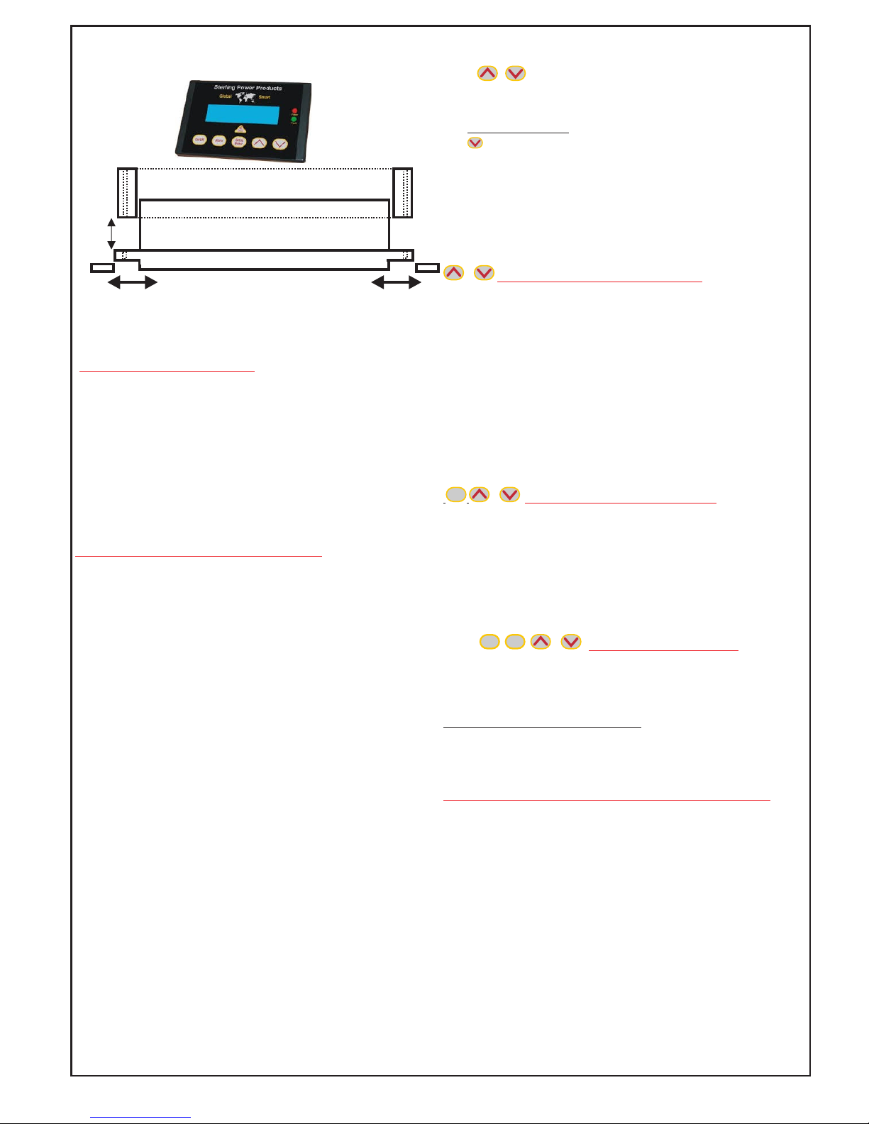
Slide parts A to expose screw holes.
For flush mount, remove part B.
For surface mount, keep part B.
After installation, replace parts A.
to install

www.sterling-power.com or www.sterling-power-usa.com
5) To reduce the risk of electrical shock, remove connection to AC shore / station power and
DC connections prior to maintenance or cleaning.
6) Turning off controls WILL NOT reduce this risk.
7) Use of extension cord should not be used unless absolutely necessary. If an extension
cord must be used, make sure:
a) That pins on plug of extension cord are the same number, size and shape of those of the
plug on the charger.
b) That the extension cord is properly wired and in good electrical condition.
c)That wire size is large enough for AC ampere rating of charger as specified in table
(page3)
6) Do not operate charger with damaged cord or plug - replace the cord or plug immediately.
7) Do not operate charger if it has received a sharp blow, been dropped, or otherwise
damaged in any way; take it to a qualified serviceman.
8) Do not disassemble charger; take it to a qualified serviceman when service or repair is
required.
9)To reduce risk of electric shock, unplug charger from outlet before attempting any
maintenance or cleaning. Turning off controls will not reduce this risk.
WARNING – RISK OF EXPLOSIVE GASES.
WORKING IN THE VICINITY OF A LEAD-ACID BATTERY IS DANGEROUS. BATTERIES
GENERATE EXPLOSIVE HYDROGEN GAS DURING NORMAL BATTERY OPERATION.
FOR THIS REASON IT IS OF UTMOST IMPORTANCE THAT EACH TIME BEFORE USING
YOUR CHARGER YOU READ THIS MANUAL AND FOLLOW THE INSTRUCTIONS
EXACTLY.
To reduce the risk of a battery explosion, follow these instructions and those published by the
battery manufacturer and any equipment you intend to use in the vicinity of the battery(s).
Carefully review the cautionary markings on this equipment.
SPARK – Be very cautious about dropping metal objects such as screwdrivers and
wrenches onto a battery. This could short-circuit the battery and immediately cause a spark
that may result in a fire or explosion.
REMOVE – All personal metal items such as rings, watches, bracelets, etc. when working
near a battery. A battery can produce a short circuit current high enough to weld a ring or any
other metal causing serious burns.
DRY CELL BATTERIES – Never use the battery charger feature to charge dry cell batteries
that are commonly used with home appliances i.e. a cordless power drill battery. These
batteries may burst and cause injury to persons and damage property.
FROZEN BATTERY – Never charge a frozen battery.
UNPACKING AND INSPECTION – Thoroughly inspect your unit.
11. PERSONAL PRECAUTIONS
a) Consider having someone close enough by to come to your aid when you work near a
lead-acid battery.
b) Have plenty of fresh water and soap nearby in case battery acid contacts skin, clothing, or
eyes.
c) Wear complete eye protection and clothing. Avoid touching eyes while working near
batteries.
d) If battery acid contacts skin or clothing, wash immediately with soap and water. If acid
enters eye, immediately flood eye with running cold water for at least 10 minutes and get
medical attention immediately.
e) NEVER smoke or allow a spark nor flame in vicinity of battery or engine.
f) Be extra cautious to reduce risk of dropping a metal tool onto battery. It might spark or
short-circuit battery or other electrical parts that may cause explosion.
g) Remove personal metal items such as rings, bracelets, necklaces, and watches when
working with lead-acid battery. A lead-acid battery can produce a short-circuit high enough to
weld a ring or the like to metal, causing a severe burn.
h) Use charger for charging a LEAD-ACID battery only. It is not intended to supply power to a
low voltage electrical system other than in a starter-motor application. Do not use battery
charger for charging dry-cell batteries that are commonly used with home appliances. These
batteries may burst and cause injury to persons and damage to property.
12. PREPARING TO CHARGE
a) if necessary to remove battery from vehicle to charge, always remove grounded terminal from
battery first. Make sure all accessories in vehicle are off, so as not to cause an arc.
b) Be sure area around battery is well ventilated while battery is being charged.
c) Clean battery terminals. Be careful to keep corrosion from coming in contact with eyes.
d) Add distilled water in each cell until battery acid reaches level specified by battery
manufacturer. Do not overfill. For a battery without removable cell caps, such as valve regulated
lead acid batteries, carefully follow manufacturer’s recharging instructions.
e) Study all battery manufacturer’s specific precautions while charging and recommended rates
of charge.
f) Determine voltage of battery by referring to battery manufactures owner’s manual and make
sure that output voltage selector switch is set at correct voltage. If charger has adjustable charge
rate, charge battery initially at lowest rate.
13. CHARGER LOCATION
a) Locate charger as far away from battery as DC cables permit.
b) Never place charge directly above battery being charged from battery will corrode and damage
charger.
c) Never allow battery acid to drip on charger when reading electrolyte specific gravity or filling bat
t ery.
d) Do not operate charger in a closed-in area or restrict ventilation in any way.
e) Do not set a battery on top of charger.
14. DC CONNECTION PRECAUTION
a) Connect and disconnect DC output clips only after setting any charger switches to “OFF”
position and removing AC cord from electric outlet. Never allow clips to touch each other.
15. FOLLOW THESE STEPS WHEN BATTERY IS INSTALLED IN VEHICLE/BOAT. A SPARK
NEAR BATTERY MAY CAUSE BATTERY EXPLOSION. TO REDUCE RISK OF A SPARE NEAR
BATTERY.
a) Position AC and DC cords to reduce risk of damage
b) Stay clear of fan blades, belts, pulleys, and other parts that can cause injury to persons.
c) Check polarity of battery posts. POSITIVE (POS,P,+) battery post usually has larger diameter
than NEGATIVE (NEG,N,-) post.
d) Determine which post of the battery is grounded
e) For negative-grounded, connect POSITIVE (RED) clip from battery charger to POSITIVE
(POS,P,+) ungrounded post of battery. Connect NEGATIVE (BLACK) clip to vehicle chassis or
engine block away from battery. Do not connect clip to carburetor, fuel lines or sheet-metal.
Connect to a heavy gauge metal part of the frame or engine block.
g) When disconnecting charger, turn switches to off, disconnect AC cord, remove clip from vehicle
chassis, and then remove clip from vehicle chassis, then remove clip from battery terminal.
h) See operating instructions for length of charge information.
16. FOLLOW THESE STEPS WHEN BATTERY IS OUTSIDE VEHICLE. A SPARK NEAR THE
BATTERY MAY CAUSE BATTERY EXPLOSION. TO REDUCE RISK OF A SPARK NEAR
BATTERY:
a) Check polarity of battery posts. POSITIVE (POS, P, +) battery usually has a larger diameter
than the NEGATIVE (NEG,N,-) post.
b) Attach at least a 24-inch-long 6-gauge (AWG) insulated battery cable to NEGATIVE (NEG, N, -)
c) Connect POSITIVE (RED) charger clip to POSITIVE (POS, P, +) post of battery.
d) Position yourself and free end of cable as far away from battery as possible - then connect
NEGATIVE (BLACK) CHARGER CLIP to free end of cable
e) Do not face battery when making final connection.
GROUNDING AND AC POWER CORD CONNECTION
a) Charger should be grounded to reduce risk of electric shock. Charger is
equipped with an electric cord having an equipment-grounding conductor and
a grounding plug. The plug must be plugged into an outlet that is properly
installed and grounded in accordance with all local codes and ordinances.
DANGER - Never alter AC cord or plug provided - if it will not fit outlet, have
proper outlet installed by a qualified electrician. Improper connection can result
in a risk of an electric shock.
b) For grounded, cord-connected battery chargers with an input rating less than
15A and intended for use with a global AC input (90V - 270V).
This battery charger is for use with a global AC input (90V - 270V) and has a
grounding plug. A temporary adaptor, as shown (figure is overleaf), may be
used to connect this plug to a two-pole receptacle, if a properly grounded outlet
is not available. The temporary adapter should be used only until a properly
grounded outlet can be installed by a qualified electrician.
DANGER - Before using adapter as illustrated, be certain that center screw of
outlet cover plate screw with a longer screw that will secure adapter ear or lug to
outlet cover plate and make ground connection to grounded outlet.
c) For all other grounded, cord-connected battery chargers:
This battery charger is for use on a circuit having a nominal rating more than
90V (or This appliance is rated more than 15A and is for use on a circuit having a
global AC input (90V - 270V) and is factory fitted with a specific electric cord and
plug to permit connection to an acceptable electric circuit. Make sure that the
charger is connected to an outlet having the same configuration as the plug. No
adapter should be used with this charger.
d) For a permanently connected battery charger:
GROUNDING INSTRUCTIONS - This battery charger should be connected to a
grounded, metal, permanent wiring system; or an equipment-grounding
conductor should be run with circuit conductors and connected to equipment-
grounding terminals or cable on battery charger. Connections to battery charger
provided with a grounding pin:
e) For a direct plug-in battery charger provided with a grounding pin:
CAUTION - Risk of fire or Electric Shock. Connect battery charger directly to
grounding receptacle (three-pong). An adapter should not be used with battery
charger.
f) For a direct plug-in battery charger having a tab for semipermanent
installation: Use only duplex receptacle having center screw; Secure unit in
place by receptacle cover screw; and CAUTION and the following or equivalent:
Risk of Electric Shock or Fire. Disconnect power to receptacle before installing
or removing unit. When removing receptacle-cover screw, cover may fall across
plug pins or receptacle may become displaced.
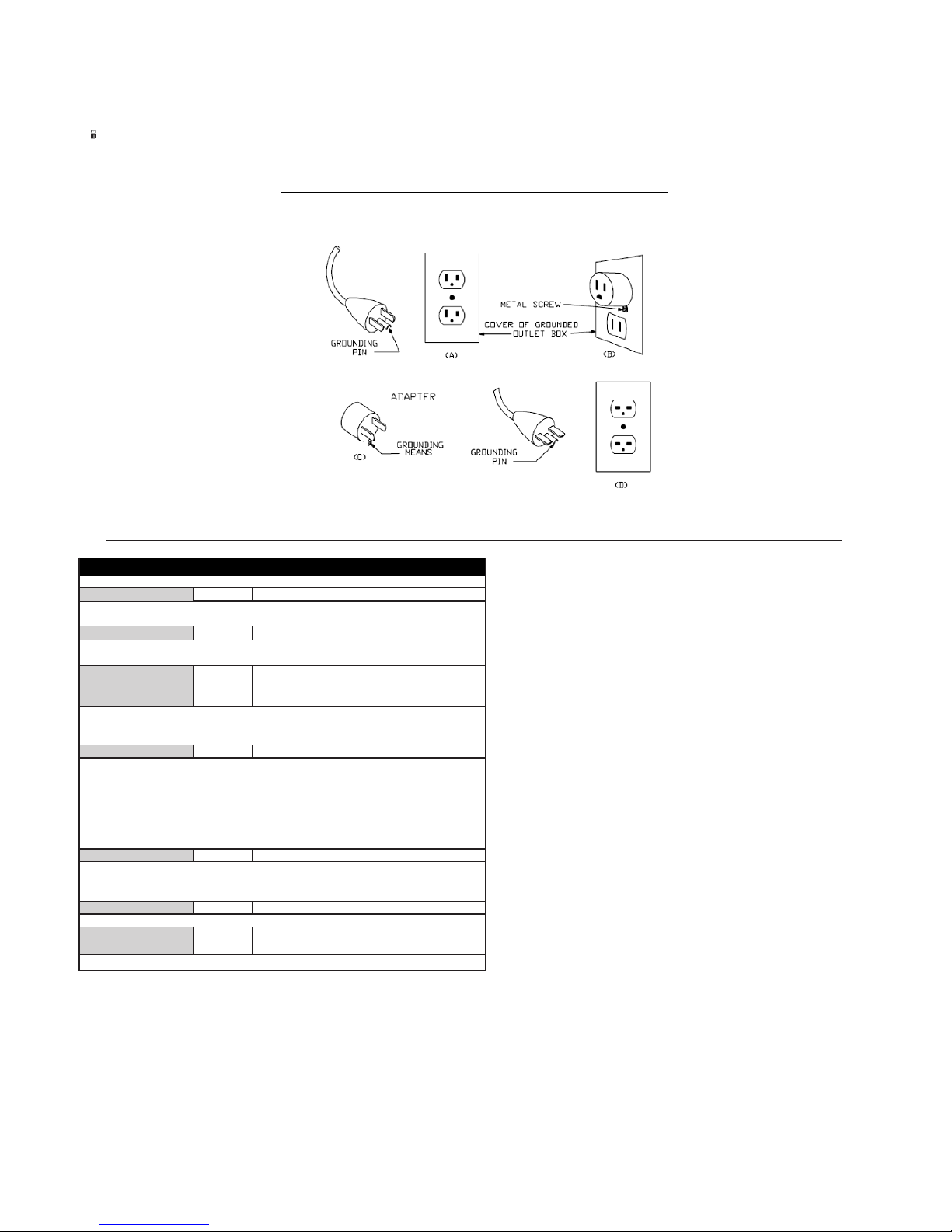
g) For a commercial battery charger that is intended to be permanently
installed and un-tampered with, the charger should be installed so that it is
not likely to be contacted by people.
DAMAGE – If any parts are missing or damaged, or the unit has been
damaged in shipping contact Sterling, do not take it back to the place of
purchase as we can offer a faster service.
Charger Fault ( Service ) Conditions
LED Label LED Colour Fault
Reverse Polarity Red Indicates a reverse polarity situation
Check DC Connections, ensure positive + ( RED) and negative - (Black and
/ or Yellow) connections are attached accordingly , also check DC fuses,
DC Volts Low Amber DC system V is less than 11V (x2 for 24v)
Wait for battery system voltage to rise over 11.0V and, if not, check and
replace defective batteries.
DC Volts High Red Indicates a high DC voltage from an external
source such as a failed alternator or wind
generator
Using a voltmeter check the voltage at the charger then switch off engine
( stop alternator ) then other charging sources to establish what is causing
the high voltage.
Charger High Temp Amber Charger has shut down due to High temp
Generally this indicates that the unit has been installed in an area of very
high ambient temperature. This unit is designed to be used in a engine room
up to 45-50 Deg C, the unit will operate in higher ambient temperatures but
will reduce it performance off the product, We recommend an ambient off no
more than 50 Deg C. The other possibility is that the internal fan may have
failed, please listen to ensure the fan is running as one would expect the fan
to be on max speed in this fault condition so if quiet this could be the problem.
Check Fan Red Fan Failure
Ensure that the cooling fan can move freely and that no debris is blocking the
fan movement, the fan should come on during the start up sequence to prove
it works, any persistent fan problems may require servicing.
Fault Red Indicates a fault
Possible internal DC fuse blown, Please contact Sterling for service options.
Auto Temp Control Red Flash High Ambient causing power reduction
to sustain output.
See charger high temperature above .
Charger Fault ( Service ) Conditions
LED Label LED Colour Fault
Reverse Polarity Red Indicates a reverse polarity situation
Check DC Connections, ensure positive + (RED) and negative - (Black and
/ or Yellow) connections are attached accordingly , also check DC fuses,
DC Volts Low Amber DC system V is less than 11V (x2 for 24v)
Wait for battery system voltage to rise over 11.0V and, if not, check and
replace defective batteries.
DC Volts High Red Indicates a high DC voltage from an external
source such as a failed alternator or wind
generator
Using a voltmeter check the voltage at the charger then switch off engine
(stop alternator) then other charging sources to establish what is causing
the high voltage.
Charger High Temp Amber Charger has shut down due to High temp
Generally this indicates that the unit has been installed in an area of very
high ambient temperature. This unit is designed to be used in a engine room
up to 45-50 Deg C, the unit will operate in higher ambient temperatures but
will reduce it performance off the product, We recommend an ambient off no
more than 50 Deg C. The other possibility is that the internal fan may have
failed, please listen to ensure the fan is running as one would expect the fan
to be on max speed in this fault condition so if quiet this could be the problem.
Check Fan Red Fan Failure
Ensure that the cooling fan can move freely and that no debris is blocking the
fan movement, the fan should come on during the start up sequence to prove
it works, any persistent fan problems may require servicing.
Fault Red Indicates a fault
Possible internal DC fuse blown, Please contact Sterling for service options.
Auto Temp Control Red Flash High Ambient causing power reduction
to sustain output.
See charger high temperature above.
MAINTENANCE
This unit is solid state software controlled and requires no constant
adjustments or attention, however, the following items should be checked:
1) On start up ensure the panel shows no fault LEDs.
2) On start up check the conditions of the fuses and ensure there is no
discolouration or corrosion round the fuse, also, check that the breaker will
manually trip and reset.
3) On start up check the fans cooling flow is not impeded by debris, keep
the area round the unit clear of items and dirt.
4) On Start up check for any traces of water / other liquids running down the
front of the unit or any evidence of this (water stains).
5) Do not use the charger, find the leak and fix the leak or remount the
charger to a safer place away from the water source.
6) Check the battery charger terminals and the battery terminals for
corrosion monthly, clean as required.
7) As per battery manufacturers’ instructions check and top up the batteries
with distilled water, as required monthly. Do not use tap or bottled water as
this will destroy the batteries.
8) Check the wires for any burning or chaffing, monthly. This is where the
wires pass through bulkheads. Repair / replace as required.
9) When the charger is on, feel the temperature of the batteries, they should
not be noticeably hotter than the surrounding ambient temperature.
If the batteries are hot to the touch then they need major investigation,
check the charger voltage is within parameters. If it is then the batterys must
be checked as they are probably defective.
Never walk away from warm-hot batteries as there is a
major problem, switch the charger off.
The package should contain the following:
1) Pro Charge Ultra
2) Owners/Installation manual
3) Temperature Sensor
DAMAGE – If any parts are missing or damaged, or the unit has been damaged in shipping -
contact Sterling. Do not take it back to the place of purchase as we can offer a faster service.
DO NOT attempt to install or operate the unit if it has been damaged in any way.
Grounding Methods

There is a 5 year return to factory warranty with Sterling Power USA
If you do NOT have a Sterling Power USA receipt the warranty length is 2 years. USA warranties must be returned to Sterling Power USA
Contact Sterling in Europe or USA. www.sterling-power.com www.sterling-power-usa.com
There is a 2 year return to factory warranty with Sterling Power UK
Pro Charge Ultra 12V/24V 10-60A and 36V/48V models:
Sterling Power - 2 years warranty
Sterling Power USA customers - 5 years warranty (Sterling Power USA receipt must be present) - return to
Sterling Power USA only
Your 100 % satisfaction is our goal. We realise that every customer and circumstance is unique. If you have a
problem, question, or comment please do not hesitate to contact us. We welcome you to contact us even after the warranty
and return time has passed.
Product Warranty:
Each product manufactured by Sterling Power UK comes with at least a 2 year limited factory warranty. Certain products
have a warranty period of time greater than 2 years. Each product is guaranteed against defects in material or workmanship
from the date of purchase. At our discretion, we shall repair or replace free of charge any defects in material or workmanship
that fall within the warranty period of the Sterling Power product. The following conditions do apply:
- The original receipt or proof of purchase must be submitted to claim warranty. If proof cannot be located a
warranty is calculated from the date of manufacture.
- Our warranty covers manufacture and material defects. Damages caused by abuse, neglect, accident, alterations
and improper use are not covered under our warranty.
- Warranty is null and void if damage occurs due to negligent repairs.
- Customer is responsible for inbound shipping costs of the product to Sterling Power either in the USA or
England.
- Sterling Power will ship the repaired or warranty replacement product back to the purchaser at their cost.
If your order was damaged in transit or arrives with an error, please contact us ASAP so we may take care of the matter
promptly and at no expense to you. This only applies for shipping which was undertaken by our company and does not
apply for shipping organised by yourself. Please do not throw out any shipping or packaging materials.
All returns for any reason will require a proof of purchase with the purchase date. The proof of purchase must be sent with
the returned shipment. If you have no proof of purchase call the vendor who supplied you and acquire the appropriate
documentation.
To make a claim under warranty, call our customer care line at ( USA 1-(207)-226-3500, England 01905 771771). We will
make the best effort to repair or replace the product, if found to be defective within the terms of the warranty. Sterling Power
will ship the repaired or warranty replacement product back to the purchaser, if purchased from us.
Please review the documentation included with your purchase. Our warranty only covers orders purchased from Sterling
Power. We cannot accept warranty claims from any other Sterling Power distributor. Purchase or other acceptance of the
product shall be on the condition and agreement that Sterling Power USA LLC and Sterling Power LTD shall not be liable for
incidental or consequential damages of any kind. Some states may not allow the exclusion or limitation of consequential
damages, so, the above limitations may not apply to you. Additionally, Sterling Power USA and Sterling Power LTD neither
assumes nor authorizes any person for any obligation or liability in connection with the sale of this product. This warranty is
made in lieu of all other obligations or liabilities. This warranty provides you specific legal rights and you may also have other
rights, which vary from state to state. This warranty is in lieu of all other, expressed or implied.
Sterling Power Products Ltd
Unit 8, Wassage way
Hampton lovett ind est
Droitwich
Worcestershire
ENGLAND WR9 0NX
Tel : 01905 771771
Fax: 01905 779434
www.sterling-power.com
Sterling Power USA
Warranty Service Center
www.sterling-power-usa.com
Customer Service & Warranty
Das ultimative Batterieladegerät
Standards:
EN61000-3-2
EN61000-3-3
EN55014-1
EN55014-2
EN60335-2-29
ProCharge U
ACHTUNG
HOCHSPANNUNG
Vor Installation stellen Sie bitte sicher, dass keine 110V /
230V Spannung an den vorgesehenen Anschlüssen
anliegt. Ansonsten besteht Lebensgefahr!
ACHTUNG
EXPLOSIONSGEFAHR
Überprüfen Sie vor Installation, dass keine entzündlichen
Dämpfe (Benzin) oder Gas in der Umgebung sind. Lüften
Sie den Installationsort vor der Installation.
NIEDRIGSPANNUNG
Zur Vermeidung von Verbrennungen, Kurzschluss und
Funkenflug, erfolgt der Anschluss an die Batterie als
letztes! Die Hauptschalter der Batterie sind zu
deaktivieren!
ACHTUNG
ACHTUNG
Während des Betriebes kann das Gerät warm werden.
Interne Komponenten können heiß werden. Niemals das
Gerät während des Betriebes öffnen!
Das Gerät ist nur zum Laden von folgenden Batterien
geeignet. Offene / geschlossene Blei-Säure-Batterien, AGM,
GEL, LiFePo4, Calcium oder Batterien, bei denen die
Ladespannungen / Strom der Spezifikation entsprechen.
Versuchen Sie NIEMALS das Gerät selbst zu reparieren. Im
Falle eines Defektes senden Sie das Gerät an Ihren Händler
oder an den Hersteller zurück!
Safety Certified by:
RoHS
compliant
EN ISO 13297
Small Craft Directive
Technische Daten des 12V 60A Gerätes
(alle anderen Modelle in Relation)
Eingangsspannung 90 - 270 VAC
Eingangsfrequenz 40 - 70 Hz
Leistungsfaktor bei 230VAC 0,95
Effizienz 88,5%
Max. Strom 10A(110VAC) / 4,8A(230VAC)
Max. Ladestrom 60A / 12VDC
Max. Spannung ( R.M.S. ) 50mVAC
Max. Fehlerstrom 0,75 mA
Toleranz Spannungsanzeige +/- 1,5%
Toleranz Stromanzeige +/- 1,5%
Benötigte Generatorleistung (Watt)
12V 20A ca. 300 Watt
12V 30A ca. 450 Watt
12V 40A ca. 600 Watt
12V 50A ca. 750 Watt
12V 60A ca. 900 Watt
24V 20A ca. 600 Watt
24V 30A ca. 900 Watt
36V 20A ca 900 watts ( NOT UL LISTED)
48V 15A ca 900 watts ( NOT UL LISTED)
Das Gerät darf nur von autorisierten und fachlich
qualifizierten Personen installiert werden (Elektriker /
Yachtelektriker). Dazu ist ein umfangreiches Wissen
von Gleich- und Wechseltrom notwendig.
Bauen Sie das Gerät nicht selber ein, wenn Sie das
fachliche Wissen hierfür nicht besitzen. Eine falsche
Installation kann die Sicherheit des Fahrzeuges und
der Personen gefährden.
Das Gerät muss auch so eingebaut werden, dass
nicht autorisierte Personen (Kinder oder Personen mit
Behinderungen) keinen Zugang zu dem Gerät haben.
Dieses Gerät ist kein Spielzeug.
CEC listed
BC
Pro Charge ULTRA
Sterling Power
In Verbindung mit dem Batterie-Lade-Adapter
ProChargeA können auch unterschiedliche
Batterietypen und andere
Spannung (z.B. 24V an
einem 12V Ladegerät oder
umgekehrt) geladen
werden.
Weitere Infos auf Seite 7.
Energiesparmodus als Standard!
Netzgerätemodus wählbar!

Auspacken und überprüfen
Überprüfen Sie die Verpackung und den Inhalt
genauestens. Es sollte folgende Teile enthalten:
1. Pro Charge Ultra Ladegerät
2. Anleitung
3. Temperatursensor inkl. Kabel
Beschädigungen
Ist das Gerät in irgendeiner Weise beschädigt oder es
fehlen Teile, informieren Sie sofort den Händler, von dem
Sie das Gerät bezogen haben.
Ist das Gerät beschädigt, installieren Sie das Gerät
NICHT!
EINLEITUNG
Wir bedanken uns vielmals für den Kauf dieses sehr
modernen und fortschrittlichen Ladegerätes.
Das ProChargeUltra ist für den Einbau in Fahrzeugen
oder festen Gebäuden gedacht, wo es NICHT mit
Wasser in Kontakt kommt.
Das PCU arbeitet mit der aktuell fortschrittlichsten
Industrie-Technologie, lädt die Batterien vollautomatisch
mit mehreren Ladestufen, wird dabei durch eine sehr
komplexe Software gesteuert und kontrolliert. Ein sehr
schneller Mikroprozessor ist die Basis.
Das Gerät hat folgende besonderen Merkmale:
Leistungsfaktor-Korrektur (PFC)
Garantiert die bestmögliche Leistung am Netz und an
einem Generator mit dem geringstmöglichen Verbrauch
Energiesparmodus (Standard)
nach einem kompletten Ladezyklus schaltet das Gerät in
einen Energiesparmodus. In diesem Modus werden die
Batterien überwacht, aber nicht geladen. In diesem
Modus funktioniert das Gerät nicht als Netzgerät.
Sobald das Gerät feststellt, dass die Batterien eine
Ladung benötigen, schaltet es wieder ein.
Netzgerätemodus (wählbar)
In diesem Modus arbeitet das Gerät nach der Ladung der
Batterien im Netzgerätemodus und versorgt somit alle
Verbraucher direkt.
Automatische Eingangsspannungserkennung
Diese Gerät kann an Spannungen von 100 - 240VAC
und Frequenzen 50Hz (Europa & Asien) / 60Hz (USA)
betrieben werden.
Digitale Anzeige
Während des Betriebes werden sowohl die aktuelle
Spannung als auch Leistung am Gerät angezeigt.
Batterietypen-Profile
11 Ladeprofile sind bereits einprogrammiert und können
ausgewählt werden. Zusätzlich kann ein individueller
Batterietyp programmiert werden, welcher sich genau an
die Anforderungen der Batterie richtet.
Auch gibt es eine Einstellung für LiFePo4 Batterien.
5 - Stufen Ladekennlinie
Die angeschlossen Batterien werden optimal und bis zu
100% durch eine 5-Stufen-Ladekennlinie geladen. Dabei
wird die Ausgleichsladungszeit automatisch berechnet,
um die Vollladung der Batterien zu gewährleisten.
Leistungswahl
Das Gerät kann sowohl am Gerät als auch über die
optionale Fernbedienung in der Leistung auf 75%, 50%
oder 25% reduziert werden. Diese Leistungsreduzierung
bleibt bestehen, bis diese wieder aufgehoben wird.
Somit kann ein leistungsstarkes Gerät auch an einer
leistungsschwachen Stromversorgung (z.B. kleiner
Generator) betrieben werden.
Desulfatierungs-Zyklus
Für offene Blei-Säure-Batterien kann ein automatischer
Desulfatierungszyklus aktiviert werden.
Standby-Modus
Wird längere Zeit kein Strom abgenommen, so schaltet
das Gerät in einen Energiesparmodus.
Effizienz
Durch eine synchronisierte Gleichrichtung mit MosFETs
anstelle von Dioden wird die Effizienz des Gerätes
gesteigert, der Stromverbrauch und die Hitzeentwicklung
reduziert.
Informations-LEDs
32 LED zeigen alle möglichen Status- und
Fehlerinformationen am Gerät an. Dadurch sind Sie
immer im Bilde, ob das Gerät einwandfrei funktioniert.
Einfache Einstellung und Programmierung
Durch 3 Tasten am Gerät können alle Funktionen und
Einstellungen vorgenommen werden. Es wird kein
Computer oder externer Elektriker benötigt, um
Einstellung vorzunehmen (keine zusätzlichen Kosten).
Vollautomatisch
Der Ladevorgang geschieht vollautomatisch und wird
ständig überwacht. Zusätzlich gibt es noch eine analoge
Sicherheitsschaltung für den Fall, dass die Elektronik
ausfallen sollte. Dann schaltet das Gerät ab.
Variable Lüfter
Die Lüftergeschwindigkeit arbeitet in mehreren Stufen um
zu garantieren, dass das Gerät möglichst leise arbeitet.
Temperatursensor inklusive
Ein Batterie-Temperatursensor liegt dem Gerät kostenlos
bei und gleicht die Spannung entsprechend an.
Optionale Fernbedienung
Eine Fernbedienung lässt sich an das Gerät anschließen
um aus der Entfernung auf fast alle Funktionen zugreifen
zu können.

INSTALLATION
HINWEIS
Das Gerät darf nur von einer fachkunden Person mit
entsprechender Ausbildung und Zertifizerung
installiert werden!
ACHTUNG! - HOCHSPANNUNG - LEBENSGEFAHR!
Bei der Installation kann es zu lebensgefährlichen
Situationen kommen, sollte auf der 110V/230V
Installationsseite eine Spannung anliegen.
Die 110V/230V Stromversorgung muss vor der
Installation komplett deaktiviert werden!
ACHTUNG!
Auch auf der Niederspannungs-Seite 12V / 24V kann
es zu Verletzungen / Verbrennungen kommen, wenn
nicht mit entsprechender Vorsicht gearbeitet wird.
Auch deshalb sollten alle Kabel immer abgesichert
werden. Entfernen Sie alle metallischen
Gegenständen von Ihren Händen und stellen Sie
sicher, dass keine Werkzeuge auf die Batterien oder
sonstige, nicht abgedeckte stromführende Kontakte
fallen können.
Vorbereitung
1. Suchen Sie einen geeigneten Installationsplatz aus.
Dieser muss möglichst kühl,trocken und gut belüftet
sein.
2. Die Befestigungswand muss fest verankert sein und
darf nicht vibrieren.
3. Der Ort muss auch gut erreichbar sein, um die
Anzeigen / Bedienung des zu ermöglichen, falls
keine Fernbedienung installiert wird.
4. Der Ort darf nicht direkt überhalb oder unterhalb der
Batterien sein, da durch ätzende Gase ansonsten
das Gerät beschädigt werden könnte.
5. Überprüfen sie diesen Installationsort auf
Feuchtigkeit und stellen Sie sicher, dass das Gerät
rundherum einen Abstand von mindestens 10cm zu
anderen Geräten oder Wänden aufweist.
6. Überprüfen Sie diesen Installationsort darauf, dass
keine losen Teile herumfliegen können und dass das
Gerät auch durch keine sonstigen Gegenstände
beschädigt werden können.
7. Wählen Sie den Installationsort so aus, dass dieser
so nah wie möglich an den zu ladenden Batterien ist.
8. Der Installationsort sollte die vertikale / senkrechte
Montage des Gerätes gewährleisten, so dass die
Anschlüsse unten und der Lüftungsschlitz des
Gehäuses oben sind. Dadurch ist gewährleistet, dass
im Falle einer Wassereintritts von oben keine
Feuchtigkeit ins Gerät eindringen kann. Dieses ist
allerdings nur gewährleistet, wenn das Wasser von
oben und ohne Druck tropft. Das Gerät ist nicht
wasserdicht!
9. Legen Sie sich alle benötigten Werkzeuge und Teile
bereit.
10. Trennen Sie die 110V / 230V Stromversorgung, so
dass keine Spannung an der Anschlussstelle anliegt.
11. Öffnen Sie alle Hauptschalter der Batterie und
nehmen Sie auch alle Kabel von den Polen ab, um
einen Kurzschluss oder Verpolung zu vermeiden.
12. Bei der Installation muss geeignete Kleidung und
Schutzmittel getragen werden (Brille, Handschuhe,
etc.).
13. Überprüfen Sie das Gerät auf Beschädigungen.
Sollte das Gerät in irgendeiner Weise
Beschädigungen aufweisen. Installieren und
betreiben Sie dieses Gerät nicht.
Installation
1. Befestigen Sie das Gerät an der ausgewählten
Wand.
2. Entfernen Sie die Anschluss-Abdeckung durch
Herausdrehen der 2 Schrauben.
3. Entfernen Sie die linke Hochspannungs-Eingangs-
Abdeckung als auch die recht Kabelklemmleiste.
4. Schließen Sie das 230V Kabel am Gerät an und
befestigen anschließend wieder die Abdeckung auf
dieser.
5. Legen Sie das 230V Kabel bis zum LS-Schalter und
befestigen dieses an den Wänden, so dass es nicht
lose herumhängt.
6. Verbinden Sie das 230V Kabel mit dem LS-Schalter,
Neutral und Schutzleiter im Sicherungskasten.
Achten Sie darauf dass das Kabel immer fest liegt
und kein Zug auf dem Kabel ist.
7. Verbinden Sie die Gleichstrom - Kabel mit den
Positiven Ausgängen und dem Negativ-Ausgang.
HINWEIS:
Ist ein positiver Ausgang nicht belegt, so muss dieser
mit einem belegten Ausgang gebrückt werden.
Dieses ist wichtig, da ansonsten keine korrekte
Ladung erfolgt.
8. Befestigen Sie die Kabelklemmleiste, so dass die
Kabel zugentlastet werden. Ist dieses nicht möglich,
weil die Kabel einen zu großen Durchmesser
aufweisen, so machen Sie bitte eine Zugentlastung
durch Befestigung der Kabel direkt an der
Befestigungswand des Gerätes unterhalb des
Anschlusses.
9. Schließen Sie den mitgelieferten Temperatursensor
an und verlegen diesen zu der größten Batterie.
10. Schließen Sie das Kabel der optionalen
Fernbedienung an, falls vorhanden.
11. Befestigen Sie die große Abdeckkappe wieder auf
dem Gerät und sichern diese mit den 2 Schrauben.
12. Führen Sie eine Installation gem. EN ISO 13297
(Boote &/ Yachten) durch, so müssen Sie jetzt das
Erdungskabel von Minus der Batterie oder eines
anderen Erdungsanschlusses ihres Fahrzeuges auf
den linken Erdungsbolzen-Anschluss des Gerätes
legen. Dadurch wird dann der Hochspannungs-
Schutzleiter mit der Erdung des Fahrzeuges
verbunden, um im Falle der Hochspannungs-
Schutzleiter-Unterbrechung einen sicheren Betrieb
zu gewährleisten. 2 Seiten weiter gibt es weitere
Informationen zu diesem Thema. Sollten Sie sich
nicht auskennen, so fragen Sie bitte einen
Fachmann.
13. Ausgehend davon, dass Sie bereits die Sicherungen
in die Ladekabel verbaut haben, schließen sie diese
jetzt an die Batterie oder den Hauptschalter mit an.
14. Immer zuerst das Minus-Kabel, dann die Plus-Kabel
anschließen!
Nachdem alle Anschlüsse hergestellt wurden, überprüfen
Sie bitte nochmals die korrekten Anschlüsse.
Anschließend kann das Gerät in Betrieb genommen
werden. Dazu sollte erst die 12V / 24V Seite wieder
aktiviert werden, indem die Hauptschalter wieder
eingeschaltet oder Kabel wieder an die Batterie
angeschlossen werden.
Dann wird die 230V Seite aktiviert. Zum Betrieb des
Ladegerät muss nun der LS-Schalter eingeschaltet
werden.
Nach Inbetriebnahme muss als erstes der korrekte
Batterietyp eingestellt werden. Hierzu lesen Sie bitte die
entsprechenden Hinweise auf den folgenden Seiten.
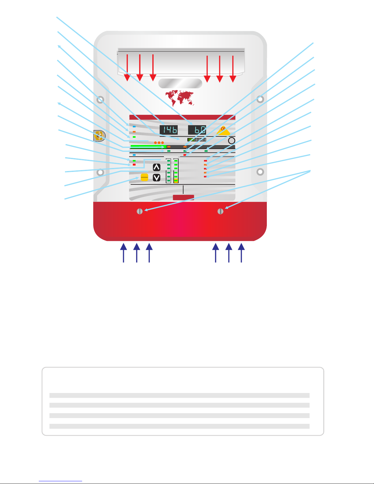
LED Funktions-Übersicht
Voreinstellung 1 Voreinstellung 2 Batterietyp Minimum Maximum
Batterietyp Voreinstellung- Information ( für 24V x alle Spannungen verdoppeln) x3 =36 V x4 =48 V
Ausgleichs-
Zeit (min) Ausgleichs-
Zeit (min)
Ladung Erhaltung Monitor Ladung Erhaltung Monitor
VDC VDC VDC VDC VDC VDC
14,8 13,6 12,8 14.7 13.4 12,8 Offene Blei-Säure 60 600
14,4 13,6 12,8 14.6 13.4 12,8 Geschlossene Blei-Säure 60 720
14,3 13,4 13,0 14,6 13,6 13,0 AGM 60 360
14,0 13,7 13,2 14,4 13,8 13,2 Gel 120 720
13,8 13,8 13,2 14,6 14,6 13,2 Lithium LiFePo4 ** 10 360
15,1 13,6 13,2 Indiv.* Indiv.* * Kalzium / Individuelle Progr. 60 360
15,5 15,5 - 15,5 15,5 - Desulfatierung / VORSICHT! 240 240
* Standard = 13,6VDC; Monitor = 13,2 - 13,6VDC ** Keine Temperaturkompensation!!
1) Amperemeter = Ausgangsstrom des Gerätes.
2) Voltmeter = Ausgangsspannung des Gerätes.
3) Leistungsanzeige = Ausgangsleistung in %
4) AC Eingangsspannung. LED leuchtet wenn
Eingangsspannung anliegt. Blinkt, wenn Gerät
ausgeschaltet wurde. Drücken Sie SETUP + Pfeil
oben für 10sec. zur Aktivierung des Gerätes.
5) Auto Temp Control = Batterie-
Temperatursensor angeschlossen,
Spannungskompensation aktiv.
6) Leistungsfaktorkorrektur aktiv.
7) Lüftungsgeschwindigkeitskontrolle, variiert je
nach Gehäusetemperatur, 3 Geschwindigkeiten
8) Stand By - Erhaltungsmodus: Gerät arbeitet
als Netzgerät mit geringem Stromverbrauch.
Spannung wurde gesenkt.
9) Maximalstromladung aktiv
10) OK: alle Funktionen im Normalbereich
11) Fehler: schwerer Fehler, muss zur Reparatur
zurückgesandt werden
12) Batterietyp Anzeige
13) Tasten zur Auswahl des Batterietyps. (siehe
Anleitung), sowie zum Ein- und Ausschalten des
Gerätes (in Verbindung mit der ENTER Taste)
14) Taste zur Auswahl der Einstellungen des
Batterietyps und zum Ein- und Ausschalten in
Verbindung mit den Pfeiltasten (13).
15) Batterieaktivierungszyklus. Alle 21 Tage
erfolgt eine Reaktivierung.(im „PS“ Modus)
15) Energiesparmodus aktiv (im „bc“ Modus)
16) Ausgleichsladung aktiv.
17) Desulfierungszyklus aktiv
18) Erhaltungsladung aktiv. Batterien sind
geladen.
19) DC Ausgang verpolt. Eventuell Sicherung
defekt.
20) DC Ausgangsspannung sehr gering.
Entweder ist das Gerät zu schwach für die
angeschlossenen Batterien oder die Verbraucher
verbrauchen mehr Strom als das Gerät liefern
kann.
21) Überspannungsschutz aktiv. Das Gerät hat
aufgrund einer zu hohen Ausgangsspannung
abgeschaltet. Entweder liegt ein interner Fehler
vor oder eine externe Spannungsquelle hat eine
zu hohe Spannung.
22) Übertemperatur: Gerät wurde zu heiß und hat
sich abgeschaltet. Umgebungstemperatur zu
hoch oder Lüftung blockiert.
23) Lüfterproblem: Lüfter blockiert oder defekt.
24) Gehäuseschrauben des Deckels. Unter dem
Deckel sind die Zugänge für die 230V
Versorgung und die Ladeanschlüsse.
Kühler
Lufteinlass
HINWEIS!
Ist ein Batterie-Temperatur-Sensor angeschlossen, werden die Spannungen entsprechend der gemessen Temperatur angeglichen (18mV/°C).
Bei Kälte erhöht sich die Ladespannung!!!
ACHTUNG!
Bei der Auswahl von Lithium / LiFePo4 gibt es keine Temperaturkompensation!!
Der Sensor arbeitet dann nur als Schutz vor Überhitzung.
OK
CHARGER MODE
AC Power
Auto Temp Control
Active PFC
Multi Speed Cooling
Volts Amps
AUTO CONSERVATION MODES
Fault
Absorption
Stand-by Battery Health Program
Fast Charge Float
DC Output Fault
DC Low Voltage
DC High Voltage Trip
High Charger temp trip
Check Fan
De-sulphation
1 2 3
SETUP
ENTER
CHARGE INFORMATION
Open lead acid
Sealed lead acid
A.G.M
GEL
Calcium / Custom
Lithium (LiFePO4)*
System self test Battery Type
Charger Output
0% 100%
High current capable of causing
sparks burns and fires, always
To avoid serious injury or death from
electric shock. Before opening, turn
off the main A/C power. Do not expose
Progressive DIGITAL software control Charger / Powerpack
RoHS
compliant
High Voltage AC Low Voltage DCWARNING
www.sterling-power-usa.com
Preset 1
Preset 2
www.sterling-power.com
*Lithium must be used in conjunction
with a lithium balancing system.
Safety Certified by: TUV
Built and tested to
UL 1236 SB
CSA C22.2-107.2 bc
Pro Charge ULTRA
GLOBAL A/C Input & Active Power Factor Correction
Sterling Power
Luftauslass
warm
1
2
3
4
5
6
7
8
9
10
11
12
13
14
15
16
17
18
19
20
21
22
23
24
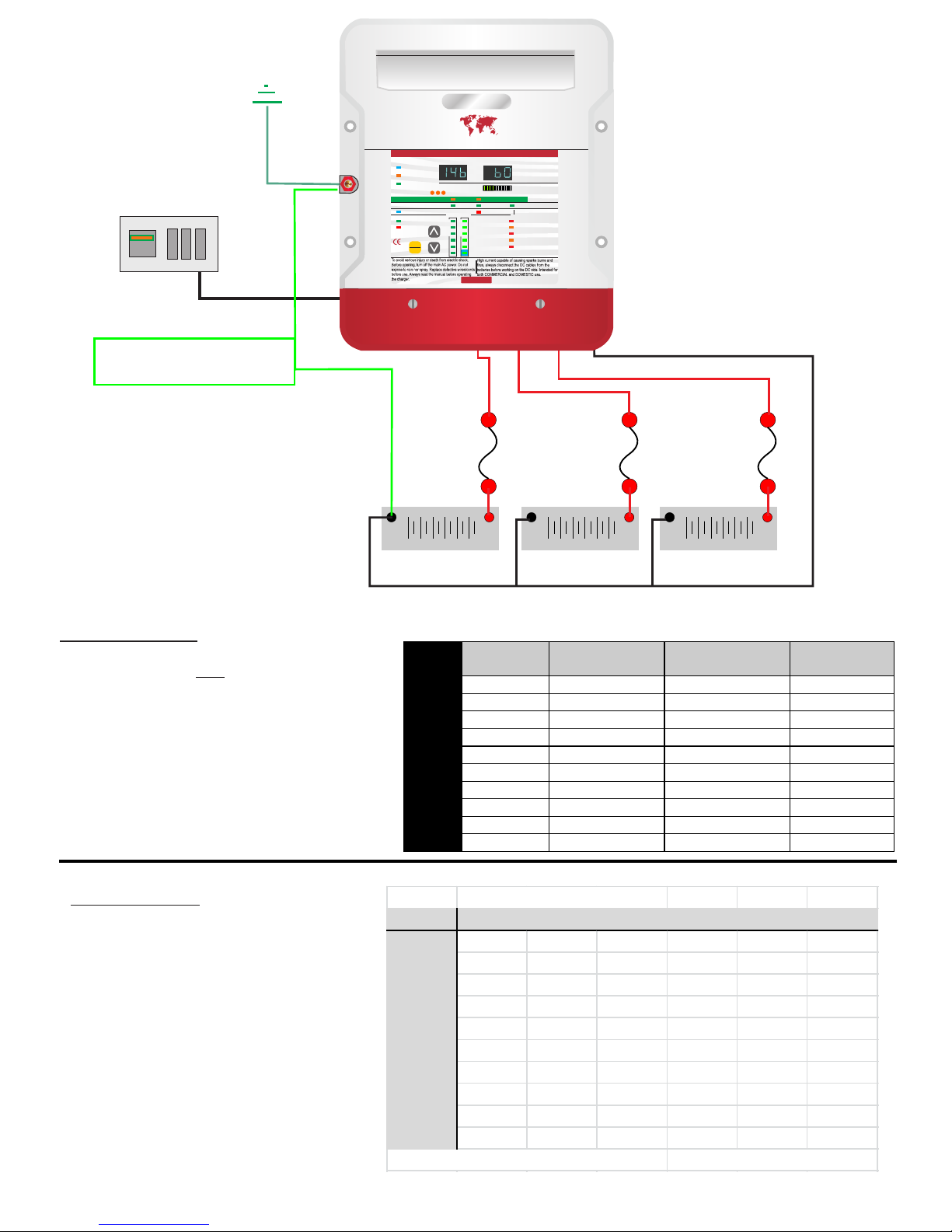
AC Breaker Size
Modell
110 Volt
Sicherung
230 Volt
Sicherung
AC
Kabel
PCU1210 6 A 4 A 3x0,75mm²
PCU1220 8 A 6 A 3x0,75mm²
PCU1230 11 A 7 A 3x1,5mm²
PCU1240 14 A 8 A 3x1,5mm²
PCU1250 16 A 10 A 3x1,5mm²
PCU1260 16 A 10 A 3x1,5mm²
PCU2420 14 A 8 A 3x1,5mm²
PCU2430 16 A 10 A 3x1,5mm²
PCU3620 16 A 10 A 3x1,5mm²
PCU4815 16 A 10 A 3x1,5mm²
AC Installation:
Das Gerät muss fest installiert und verbunden
werden. Dieses ist kein mobiles Gerät!.
Verlegen Sie ein NYM-J Kabel vom AC-
Ladegerät Eingang zum LS-Schalter. Besser
wäre eine H07RN-F Gummischlauchleitung, da
diese auch beständig gegen Öle und Fette ist,
sollte das Gerät im Motorraum installiert
werden. Beim H07RN-Fi sind aber unbedingt
Aderendhülsen zu verwenden !!
Fixieren Sie das Kabel und achten Sie darauf,
dass es nirgendwo scheuert.
DC - Sicherungauswahl:
Jeder Ausgang sollte mit einer
Sicherung versehen werden. Die
Sicherung sollte ca. 20% höher
ausfallen, als die maximale Leistung
des Ladegerätes. Diese sichert das
Kabel ab.
Schutzleiter / Erdung.
Dieses ist ein sehr sensibles Thema.
Gemäß EN ISO 13297 muss der Landstrom-
Schutzleiter mit der Erdung eines Bootes
verbunden sein. Da fast immer der Motor
über die Welle / Saildrive / Z-Drive geerdet
ist, muss somit der Schutzleiter mit Batterie-
Minus verbunden werden. Ohne galvanische
Trennung (Trenntrafo oder galvanischer
Isolator) kann es allerdings zu galvanischen
Strömen kommen, welche die vorhandenen
Unterwasseranoden schnell aufbrauchen
können und anschließend die zu
schützenden Metalle aufbrauchen.
In diesem Falle sollte ein galvanischer
Isolator (z.B. ZS16A) oder ein Trenntrafo
eingebaut werden.
Der Anschlussbolzen auf der linken Seite des
Ladegerätes (Erdung) ist mit dem AC-
Schutzleiter (gelb-grünes Kabel) intern
verbunden!!
Bei Stahl-/Aluminium-Booten ist besondere
Vorsicht geboten.
Lassen Sie sich von einem Fachmann
beraten!
Schutzleiter/ Erdung /Chassis
(Boot Erdung)
+
_
Batterie oder -bank. +
_
Batterie oder -bank. +
_
Batterie oder -bank.
DC
Sicherung
20% mehr Ampere
als max. Strom
DC
Sicherung
20% mehr Ampere
als max. Strom
DC
Sicherung
20% mehr Ampere
als max. Strom
LS-Schalter
Ein nicht genutzter Ausgang muss mit einem
genutzten Ausgang gebrückt werden, so dass
keine unbelegten Ausgänge vorhanden sind.
Dieses würde zu einer inkorrekten Ladung
führen.
Verwenden Sie mehradrige Kabel, welche bis zu
einer maximalen Temperatur von 150°C ausgelegt
sind. Diese erhalten Sie im Fachhandel.
Nur eine Spannung möglich, je nach Gerät. Entweder 12V oder 24V.
Trotz der 3 Ausgänge lassen sich nur Batterien gleicher Spannung laden,
da es nur einen gemeinsamen Negativ/Minus- Anschluss gibt.
Verteilung
Boot / Fzg.
ĜŌPŅÑǾŌÞŌŊ ŖÞǾ ĘMPPÑǾÒÑ
Modell bis 1m bis 2m bis 3m bis 4m bis 5m bis 6m
PCU1210 2,5 mm² 4 mm² 6 mm² 10 mm² 10 mm² 16 mm²
PCU1220 4 mm² 10 mm² 16 mm² 16 mm² 25 mm² 25 mm²
PCU1230 6 mm² 16 mm² 25 mm² 25 mm² 35 mm² 35 mm²
PCU1240 10 mm² 16 mm² 25 mm² 35 mm² 50 mm² 50 mm²
PCU1250 10 mm² 25 mm² 35 mm² 50 mm² 50 mm² n.E.
PCU1260 16 mm² 25 mm² 50 mm² 50 mm² n.E. n.E.
PCU2420 4 mm² 10 mm² 16 mm² 16 mm² 25 mm² 25 mm²
PCU2430 6 mm² 16 mm² 25 mm² 25 mm² 35 mm² 35 mm²
PCU3620 4 mm² 10 mm² 16 mm² 16 mm² 25 mm² 25 mm²
PCU4815 4 mm² 6 mm² 10 mm² 10 mm² 16 mm² 16 mm²
maximaler Spannungsabfall: 1,5% n.E. = nicht empfehlenswert
DC Installation:
Installieren Sie das Gerät zu nah wie
möglich and den Batterien, um die
Kabelquerschnitte gering zu halten. Es
gilt jeden Spannungsabfall zu den
Batterien zu vermeiden. Legen Sie die
Kabel zu kurz wie möglich zu den
Batterien und vermeiden Sie Umwege.
gem. EN ISO 13297
(siehe Hinweis oben rechts!)
Pro Charge ULTRA
GLOBAL AC Input & Active Power Factor Correction
Sterling Power
OK
CHARGER MODE
AC Power
Auto Temp Control
Active PFC
Multi Speed Fan
Volts Amps
AUTO CONSERVATION MODES
Fault
Absorption
Stand-by Battery Health Program
Fast Charge Float
DC Output Fault
DC Low Voltage
DC High Voltage Trip
High Charger temp trip
Check Fan
De-sulphation
1 2 3
SETUP
ENTER
CHARGE INFORMATION
Open lead acid
Sealed lead acid
A.G.M
GEL
Calcium / Custom
Lithium (LiFePO4)*
System self test Battery Type
Charger Output
0% 100%
Progressive DIGITAL software control Charger / Powerpack
High Voltage AC Low Voltage DCWARNING
www.sterling-power-usa.com
Preset 1
Preset 2
www.sterling-power.com
*Lithium must be used in conjunction
with a lithium balancing system.
Safety Certified by: TUV
Built and tested to
UL 1236 SB
CSA C22.2-107.2
RoHS
compliant
CEC
approved
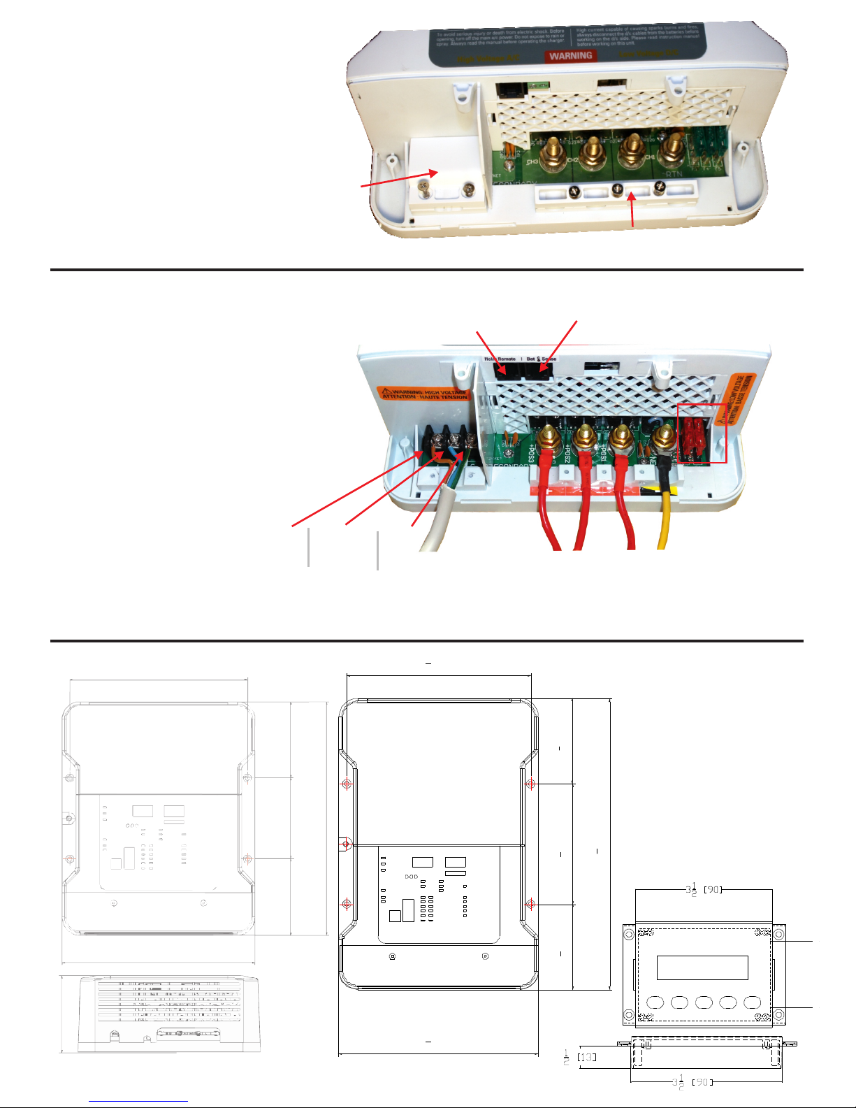
Entfernen Sie die beiden Schrauben
unten auf der Frontabdeckung.
Darunter befindet
sich der Hauptverkabelungs-Bereich
Hochspannung
AC Abdeckplatte
und Klemme
DC Kabelklemme
Fernbedienung
Phase Neutral Erde
1 2 3 Negativ
rot rot rot Gelb oder Schwarz
Batterie positiv
ى5
8[93]
51
8[130]35
8[93]
73
4 [198]
81
2 [215]
123
8[315]
ProMariner
Pro Nautic iQ
12-60
198 mm 7 3/4 inch
85 mm
3 3/8 inch
90 mm
3 ½ inch
260 mm
10 1/4 inch
85 mm
3 and 3/8 inch
215 mm
8 ½ inch
90 mm
3 ½ inch
44 mm
1 3/4 inch
Abmessungen
in inch
und mm
12V 10-40A
24V 20A
12V 50-60A
24V 30A
36V 20A
48V 15A
Batterietemperatursensor Buchse
SICHERUNGEN
DC
Entfernen Sie die beiden Schrauben im AC Bereich
und die 3 Schrauben bei der DC Klemme um die
passenden Kabel anzuschließen
AC Eingang 90 - 270 VAC
Garantieren Sie dass sichere Verbindungen
und korrekte Crimpzangen etc verwendet werden
DC 12V oder 24V je nach Gerät
Fernbedienung
Die Fernbedienung wird in die entsprechende RJ12
Buchse eingesteckt.
Nach Anschließen der Fernbedienung läßt
sich nur noch der Batterietyp am Gerät
selbst ändern. Alle anderen Funktionen nur noch
über die Fernbedienung.
Batterietemperatursensor
Der Temperatursensor hat auch
einen RJ11-Stecker und wird
am Gerät in die entsprechend
markierte Buchse gesteckt.
Earth /chassis
boats bonding
+
_
12V Starterbatterie
geschl. Blei-Säure
+
_
12V Servicebatterie
LiFePO4 Lithium
+
_
24V Bugstrahlruderbatterie
AGM
Pro Charge ULTRA
GLOBAL A/C Input & Active Power Factor Correction
Sterling Power
ProCharge A - Batterie-Lade-Adapter
optionale Fernbedienung
(zum Betrieb nicht benötigt)
Beispiel: Eine 12V Starterbatterie (geschlossene Blei-Säure), eine Lithium-Batterie und eine 24V AGM Bugstrahlruderbatterie.
Ladegerät ist
auf geschlossene
Blei-Säure-Batterien
14,4V eingestellt
ProChargeA
eingstellt auf LiFePO4
ProChargeA
eingstellt auf
AGM
Sterling Power Products
H Charge Float
In / Unit Bat - Chem - Unit Out / Rem
Batt.
V12.2
Temp
Menu
Setup
Volts
Alarm
Select
Audible alarm on/off
hold >5 sec
Unit on/off
hold > 5 sec
Fault
Absorption
Condi
12V 12V 24V
Problem
Das Problem kennen sicherlich viele. Man hat verschiedene
Batterietypen (offene-Blei-Säure, Gel, AGM oder andere) für
Starter-, Verbraucher und eventuell Bugstrahlruder/Heizung)
und möchte mit einem Ladegerät diese verschiedenen
Batterietypen laden. Oder eine Batteriebank hat 24V. Nur läßt
sich das 12V Ladegerät nur auf einen Batterietyp einstellen.
Eine 24V Batterie läßt sich damit sowieso nicht laden. Was
nun?
Lösung
Man installiert ein oder zwei ProChargeA Batterie-
Ladeadapter.
Funktion
Der ProChargeA lädt die angeschlossene Batterie
entsprechend des eingestellten Batterietyps. Dabei ist es
unabhängig, was für eine Kennlinie das angeschlossene
Ladegerät hat.
Somit können Sie moderne Batterietypen auch mit einem alten
Ladegerät laden.
Mit dem ProChargeA und einem Ladegerät mit 2 oder mehr
Ausgängen, lassen sich auch unterschiedliche Batterietypen
mit 1 Ladegerät laden. Das Ladegerät wird auf einen
Batterietyp eingestellt und das ProChargeA wird auf den
anderen Batterietyp eingestellt.. Es können auch mehrere
ProChargeA Geräte an ein Ladegerät angeschlossen werden.
Kennlinie + Batterietypen
Das ProChargeA lädt die angeschlossene Batterie mit einer
optimalen 5-Stufen IUoUo Kennlinie. Dabei wird die
Ausgleichsladungszeit automatisch berechnet, um eine 100%
Ladung zu gewährleisten.
Bei der Einstellung des Batterietyps haben Sie die Auswahl
zwischen 8 verschiedenen Ladeprofilen. Diese eignen sich für
geschlossene oder offene Blei-Säure, Gel, AGM, Kalzium und
LiIon/LiFePo Batterien..
Anschluss
Das ProChargeA wird zwischen das Ladegerät und die
Batterien geschaltet. Die Maximalleistung des Ladegerätes darf
60A nicht überschreiben. Die minimale Leistung sollte bei 10A
liegen. Ein Temperatursensor für die Batterie liegt dem Gerät
bei.
24V laden über 12V Ladegerät
Mit dem BCM1224 lassen sich auch 24V Batterien über ein 12V
Ladegerät laden. Dabei ist die Leistung auf 10A bei 24 V
begrenzt.
Optionale Fernbedienung
Über eine optionale Fernbedienung lassen sich alle relevanten
Informationen wie Eingangs- und Ausgangsspannung,
Temepraturen, Kennlinienstufe, Alarme, etc. anzeigen. Auch
kann man das Gerät über die FB deaktivieren.
Merkmale und Funktionen
Eingangsspannung > 12VDC / > 24VDC
IUoUoUo - Ladekennlinie (5-Stufen)
automatische Erkennung der Batteriebankgröße
und der dazu gehörigen Ausgleichsladungszeit
8 verschiedene Batterietypen einstellbar
GEL1, GEL2, AGM1, AGM2, geschlossene Blei
Säure, LiFePo, Calcium, offene Blei Säure,
1 Batterieausgang
6 LED Informationsanzeige
Ringanschlüsse
Überlast- und Überhitzungsschutz
Kurzschluss- und Verpolungsschutz
Spritzwassergeschütztes Gehäuse
(Schutzklasse IP65)
inkl. Batterie-Temperatur-Sensor
optionaler Temperatur-Kettensensor
optionale Fernbedienung

Geräte Modus - Übersicht
bc (Battery Charger)
- Laden und Energie sparen
(Standardeinstellung)
Das ProCharge Ultra ist jetzt mit einer sehr
leistungseffizienten Technik ausgestattet, welche die
Ladung und Erhaltung der Batterien gewährleistet.
Diese Einstellung dient dazu Energie einzusparen,
indem das Ladegerät in einen Betriebszustand
versetzt wird, in dem fast keine Energie mehr
verbraucht wird. Dieser Modus ist besonders
interessant, wenn das Gerät über einen längeren
Zeitraum betrieben wird.
ACHTUNG: Wenn keine Batterie angeschlossen ist,
arbeitet das Gerät nicht.
Wenn das gewünscht ist, muss der
Netzgerätemodus aktiviert werden
PS (Power Supply)
- Laden und Versorgen
In dem Fall, dass das Gerät auch Verbraucher
versorgen soll, wenn keine Batterie angeschlossen
ist oder Sie ständige Verbraucher während und
nach dem Ladevorgang an den Batterien
angeschlossen haben (z.B. Kühlschrank, Heizung,
etc.) empfiehlt sich der Netzgeräte-Modus (PS). In
diesem Modus schaltet das Gerät NICHT in einen
Energiesparmodus. Stattdessen wird die
Erhaltungsladungsspannung ständig gehalten und
etwaige Verbraucher werden direkt vom ProCharge
Ultra versorgt.
Modus - Auswahl
Beim Einschalten des Gerät oder einem
aktivierten Selbsttest startet das Gerät mit der
Anzeige „888" zur Überprüfung, ob alle
Segmente des Displays funktionieren.
Anschließend zeigt das Display den
eingestellten Modus „bc“ oder „PS“ für 7
Sekunden an.
Ist kein Modus programmiert, wird als Standard
der „bc“-Modus definiert. Ist ein anderer Modus
eingeschaltet worden, so wird beim
Wiedereinschalten der gespeicherte Modus
verwendet.
Wird der Modus umgeschaltet, wird auch der
Batterietyp wieder auf den Standard-Typ
(geschlossene Blei-Säure) gestellt.
Anschließend kann wieder der gewünschte
Batterietyp eingestellt werden.
Möchten Sie den Modus ändern, haben Sie ein
7 Sekunden Zeitfenster nach dem Einschalten
des Geräes während entweder „bc“ oder „PS“
angezeigt wird.
1. Durch Drücken der Tasten é oder ê (Pfeil-
oben oder Pfeil-unten) wechseln Sie zwischen den
Modi.
2. Nach Auswahl des gewünschten Modus
drücken Sie die Taste SETUP/ENTER.
Nun ist der gewünschte Modus aktiviert und
gespeichert. Beim nächsten Start wird dieser
Modus wieder aktiviert.
Funktionsweise Energiesparmodus
Nachdem die Batterien geladen sind, schaltet das
Gerät automatisch in den Energiesparmodus. In
diesem Modus überwacht und steuert die
Spannungen gemäß der Spannungstabelle. Die
Stand-by LED leuchtet in diesem Modus.
Während dieser Funktion können Anzeigen
abgerufen werden, indem eine beliebige Taste
gedrückt wird. Dieses versetzt das Gerät in einen
Wartungs-Anzeige-Modus.
Programmierung / Einstellungen am Gerät
STAND-BY - SCHALTUNG
1. Drücken Sie die Tasten Setup/Enter + ê (Pfeil-
unten) für 10 Sekunden.
2. Das Gerät schaltet in Stand-by und die LED AC-
Power blinkt.
AKTIV - SCHALTUNG (aus dem Standby-Modus)
1. Drücken Sie die Tasten Setup/Enter + é (Pfeil-
oben) für 10 Sekunden.
2. Das Gerät schaltet in den Lademodus und die
LED AC-Power leuchtet.
BATTERIE-TYP - EINSTELLUNG
1. Drücken Sie die Taste Setup/Enter für mindestens
6 Sekunden.
2. Der aktuelle Batterietyp wird durch blinken
angezeigt.
3. Durch Drücken der Tasten é oder ê (Pfeil-oben
oder Pfeil-unten) wechseln Sie den Batterietyp.
Gleichzeitig wird die Ladeschluss- und
Erhaltungsladungsspannung angezeigt.
4. Nachdem Sie den für Sie richtigen Batterietyp
ausgewählt haben, drücken Sie die Taste

Setup/Enter. Der Batterietyp leuchtet jetzt konstant und
das Gerät fängt an zu laden.
BENUTZERDEFINIERTEN BATTERIETYP EINSTELLEN
1. Diese Einstellung sollte mit Vorsicht und Kenntnis
der spezifischen Ladungs- und
Erhaltungsladungs-Spannung der zu ladenden
Batterie erfolgen.
2. Führen Sie die Punkte 1 - 3 der Batterie-Typ
Einstellung durch.
3. Wählen Sie den Batterietyp „Custom“ aus.
4. Auf beiden Anzeigen erscheint jetzt der Wert 13.6
(12V) oder 27.2 (24V).
5. Warten Sie, bis die LED „Absorption“ blinkt.
6. Stellen Sie den gewünschten Wert mit den Tasten
é oder ê (Pfeil-oben oder Pfeil-unten) für die
Ladeschlussspannung ein (max. 15,1V / 30,2V).
7. Drücken Sie die Taste Setup/Enter.
8. Jetzt blinkt die LED „Float“ und die Spannung für
die Erhaltung der Batterie kann mit den Tasten é
oder ê (Pfeil-oben oder Pfeil-unten) eingestellt
werden.
9. Anschließend drücken Sie die Taste Setup/Enter
zur Bestätigung. Die Spannungen werden jetzt in
der Einstellung Custom gespeichert.
10. Das Gerät startet mit den neuen Einstellungen.
SELBSTTEST
1. Halten Sie die Taste Setup/Enter und die Tasten
é und ê (Pfeil-oben und Pfeil-unten) gleichzeitig
für mindestens 6 Sekunden gedrückt.
2. Das Gerät führt einen Selbsttest durch,
währenddessen die LED „self test“ blinkt.
3. Sobald das blinken aufgehört hat, ist der
Selbsttest beendet.
DESULFATIERUNGS-MODUS
Eine Aktivierung des Desulfatierungs-Modus ist nur möglich,
wenn vorher einer der beiden „offene Blei-Säure“
Batterietypen aktiviert war. Nur mit offenen Blei-Säure-
Batterien darf dieser Modus erfolgen, da die Batterien stark
gasen werden. Vorher und nachher muss der Wasserstand
der Batterien kontrolliert und ausgeglichen werden.
ACHTUNG! Nur mit absolutem Fachwissen darf dieser
Modus zur Reaktivierung von Batterien benutzt werden!!
Entfernen Sie alle Verbraucher von der Batterie, da
während dieses Modus 15,5V (31V) an der Batterie
anliegen werden und Verbraucher zerstört werden
könnten. Dieser Vorgang sollte nicht öfter als 4x pro Jahr
erfolgen.
1. Führen Sie die Punkte 1 - 3 der Batterie-Typ
Einstellung durch.
2. Drücken Sie so lange die Taste ê (Pfeil-unten),
bis die LED „Desulphation“ leuchtet.
3. Zur Bestätigung müssen Sie jetzt die Tasten é
und ê (Pfeil-oben und Pfeil-unten) für 3
Sekunden drücken.
4. Die Batterien werden jetzt für 240 Minuten mit
einer erhöhten Spannung zur Desulfatierung &
Reaktivierung geladen. Eine Unterbrechung ist
nur durch das gezielte Abschalten der
Stromversorgung (LS-Schalter) möglich!!
5. Nach Ablauf von 240 Minuten schaltet das Gerät in
die vorher ausgewählte Batterie-Typen- Einstellung
(muss eine der beiden „offene Blei-Säure“
Einstellungen gewesen sein) zurück.
LEISTUNGS - EINSTELLUNG
1. Drücken Sie die Tasten é und ê (Pfeil-oben und
Pfeil-unten) für mindestens 15 Sekunden
gleichzeitig.
2. In der linken Anzeige erscheint „PL“ und rechts
„100" oder der vorher eingestellte Wert.
3. Durch Drücken der ê (Pfeil-unten) kann die
Leistung auf 75%, 50% oder 25% oder
zurückgestellt werden. Nach kurzem Warten
wechselt die Anzeige in den maximalen Ampere-
Wert.
4. Nach Auswahl der gewünschten Leistung, drücken
Sie die Taste Setup/Enter.
Sollte keine Eingabe oder Bestätigung innerhalb von 15
Sekunden erfolgen, schaltet das Gerät in die 100%
Leistung zurück.
WERKS - RÜCKSTELLUNG
(Alle Werte werden in den Auslieferzustand
zurückversetzt)
1. Führen Sie die Punkte 1 - 3 der Batterie-Typ
Einstellung durch.
2. Drücken Sie so lange die Taste ê (Pfeil-unten), bis
die keine Batterietyp LED und auch keine LED
„Desulphation“ leuchtet.
3. In der Anzeige wird links „FAC“ und rechts „DEF“
angezeigt.
4. Drücken Sie die Taste Setup/Enter. Das Gerät
startet neu mit den Werkseinstellungen.
Sterling Power Products
Power
Fault
On/Off Alarm Setup
Enter
ACHTUNG!
Die Fernbedienung funktioniert nur, wenn Sie
bereits beim Einschalten des Gerätes verbunden ist.
Wird die Fernbedienung während das Ladegerät
bereits eingeschaltet ist (mit Strom versorgt wird)
angeschlossen, funktioniert diese nicht korrekt.
ERSTES EINSCHALTEN UND SPRACHAUSWAHL:
Nach dem ersten Einschalten erscheint:
„Language Select: English“ für 5 Sekunden.
Durch Drücken der Tasten é und ê (Pfeil-oben und Pfeil-
unten) wählen Sie „Deutsch“ aus und bestätigen Sie
dieses durch Drücken der Taste Setup/Enter.
Programmierung / Einstellungen an der Fernbedienung

HINTERGRUND BELEUCHTUNG
1. Drücken Sie die Taste On/Off für 1 Sekunde.
2. Die Hintergrundbeleuchtung schaltet ein oder aus.
STAND-BY - SCHALTUNG
1. Drücken Sie die Taste On/Off für 3 Sekunden.
2. Das Gerät schaltet in Stand-by.
AKTIV - SCHALTUNG (aus dem Standby-Modus)
1. Drücken Sie die Taste On/Off für 3 Sekunden.
2. Das Gerät schaltet in den Lademodus.
BATTERIE-TYP - EINSTELLUNG
Einstellung nur am Ladegerät möglich!
SELBSTTEST
1. Halten Sie die Tasten Setup/Enter und die Tasten é
und ê (Pfeil-oben und Pfeil-unten) gleichzeitig für
mindestens 5 Sekunden gedrückt.
2. Das Gerät führt einen Selbsttest durch,
währenddessen am Ladegerät die LED „self test“
blinkt und „self test“ angezeigt wird..
3. Sobald das blinken aufgehört hat, ist der Selbsttest
beendet.
4. Die Anzeige meldet „System OK“.
5. Drücken Sie die Taste Setup/Enter. Nun wählen Sie
entweder „Blättern“ oder eine Anzeige Ihrer Wahl
durch Drücken der Tasten é oder ê (Pfeil-oben oder
Pfeil-unten).
6. Bestätigen Sie die Auswahl durch Drücken der Taste
Setup/Enter.
LEISTUNGS - EINSTELLUNG
1. Drücken Sie die Tasten é und ê (Pfeil-oben und
Pfeil-unten) für mindestens 15 Sekunden gleichzeitig.
2. Durch Drücken der Tasten é oder ê (Pfeil-oben
oder Pfeil-unten) kann die Leistung auf 75%, 50%
oder 25% oder auf 100% zurückgestellt werden.
Gleichzeitig wird der maximal Ampere-Wert angezeigt.
3. Nach Auswahl der gewünschten Leistung, drücken Sie
die Taste Setup/Enter.
Sollte keine Eingabe oder Bestätigung innerhalb von 15
Sekunden erfolgen, schaltet das Gerät in die 100%
Leistung zurück.
WERKS - RÜCKSTELLUNG
(Alle Werte werden in den Auslieferzustand
zurückversetzt)
1. Halten Sie die Tasten Alarm und Setup/Enter und die
Tasten é und ê (Pfeil-oben und Pfeil-unten)
gleichzeitig für mindestens 3 Sekunden gedrückt.
2. Für einige Sekunden wird „Werkseinstellung“
angezeigt.
3. Das Gerät startet mit den Werkseinstellungen.
ALARMTON DEAKTIVIERUNG
Durch Drücken der Taste Alarm kann der Alarmton
ein oder ausgeschaltet werden.
„ALARM EIN“ = Alarmton eingeschaltet
„ALARM AUS“ = Alarmton ausgeschaltet.
Standardmäßig ist der Alarmton eingeschaltet.
ANZEIGEN - MODUS / AUTOMATISCHER WECHSEL
Hier ist es möglich die gewünschte Anzeige permanent
anzuzeigen oder einen automatischen Wechselmodus
(alle 3 Sekunden) auszuwählen.
Automatischer Wechsel
1. Drücken Sie die Taste Setup/Enter.
2. „Blättern“ wird angezeigt.
3. Zur Bestätigung drücken Sie die Taste Setup/Enter.
4. Die Anzeige wechselt nun alle 3 Sekunden.
Auswahl der gewünschten Anzeige
1. Drücken Sie die Taste Setup/Enter.
2. „Blättern“ wird angezeigt.
3. Drücken der Taste ê (Pfeil-unten) wählen Sie die
gewünschte Anzeige aus.
4. Zur Bestätigung drücken Sie die Taste Setup/Enter
SPRACHAUSWAHL NEU EINSTELLEN
1. Drücken Sie die Taste Setup/Enter.
2. Die aktuelle Sprache wird blinkend für 5 Sekunden
angezeigt.
3. Während dieser 5 Sekunden können Sie durch
Drücken der Tasten é oder ê (Pfeil-oben oder Pfeil-
unten) die Sprache neu auswählen.
4. Bestätigen Sie die Auswahl durch Drücken der Taste
Setup/Enter.
5. Wird keine Auswahl getroffen, bleibt die vorherige
Sprachauswahl erhalten.
6. Die Anzeige geht in den Normalbetrieb über.
Folgende Sprachen stehen zur Auswahl:
Englisch, Deutsch, Spanisch, Italienisch, Französisch
Folgende Anzeigen stehen zur Verfügung:
1. Ladegerät Typ Geräte-Modell
2. Gerätestatus zeigt akt. Status mit Werten
an (Standardeinstellung)
3. Batterietyp Auswahl eingestellter Batterietyp
4. Ausgleichsladungszeit verbleibende Ausgleichs-
ladungszeit
5. Laufzeit Zeit seit Einschalten
6. Leistung max. eingestellte Leistung
7. Bat Temperatur Batterie-Temperatur
8. Ladegerät Temp. Ladegerät-Temperatur
9. Trafo Temp Trafo-Temperatur
10. Fehler Fehler *
11. Hersteller Sterling Power Info
12. Gesamtlaufzeit Gesamtlaufzeit Gerät
13. Software Version Software Version
* Fehler: Normalerweise wird „Keine Fehler“ angezeigt.
Erscheint eine Fehlermeldung, können durch Drücken
der Pfeiltasten oben/unten weitere Fehlermeldungen
angezeigt werden. Durch Drücken der Taste
„Setup/Enter“ wird das Problem erklärt.
Table of contents
Languages:
Other Sterling Power USA Batteries Charger manuals


