Eastey EA Professional Series User manual

EA
Auto L-Sealer
Professional Series
User Guide
EA3050TK, EA3070TK, EA30100TK,
EA4050TK, EA4070TK, EA40100TK,
EA5050TK, EA5070TK, and EA50100TK


EA
Auto L-Sealer
Professional Series
User Guide
Revised 04/11/2022
P/N EA001000 Rev A1
Copyright and Trademarks
Copyright ©2016-2022 Engage Technologies Corporation
All rights reserved. All trademarks and brand names
are the property of their respective owners.
Eastey
7041 Boone Ave. N.
Brooklyn Park, MN 55428
Phone: (763) 428-4846; Fax (763) 795-8867; 1-800-835-9344
www.eastey.com
EA3050TK, EA3070TK, EA30100TK,
EA4050TK, EA4070TK, EA40100TK,
EA5050TK, EA5070TK, and EA50100TK


Contents
Safety ............................................................................................................................. 7
General Safety Precautions .......................................................................................... 7
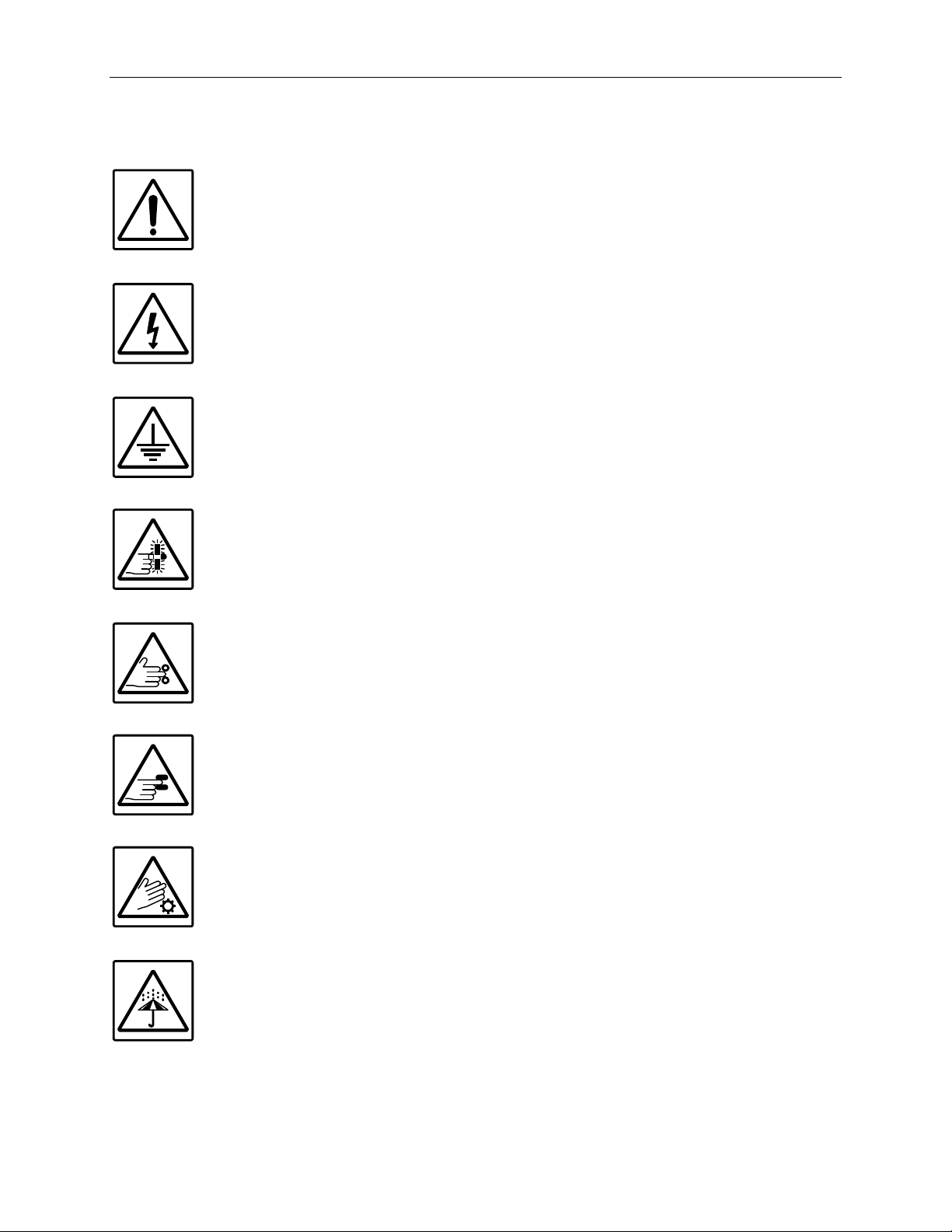
Explanation of Symbols................................................................................................. 9
Introduction ................................................................................................................. 10
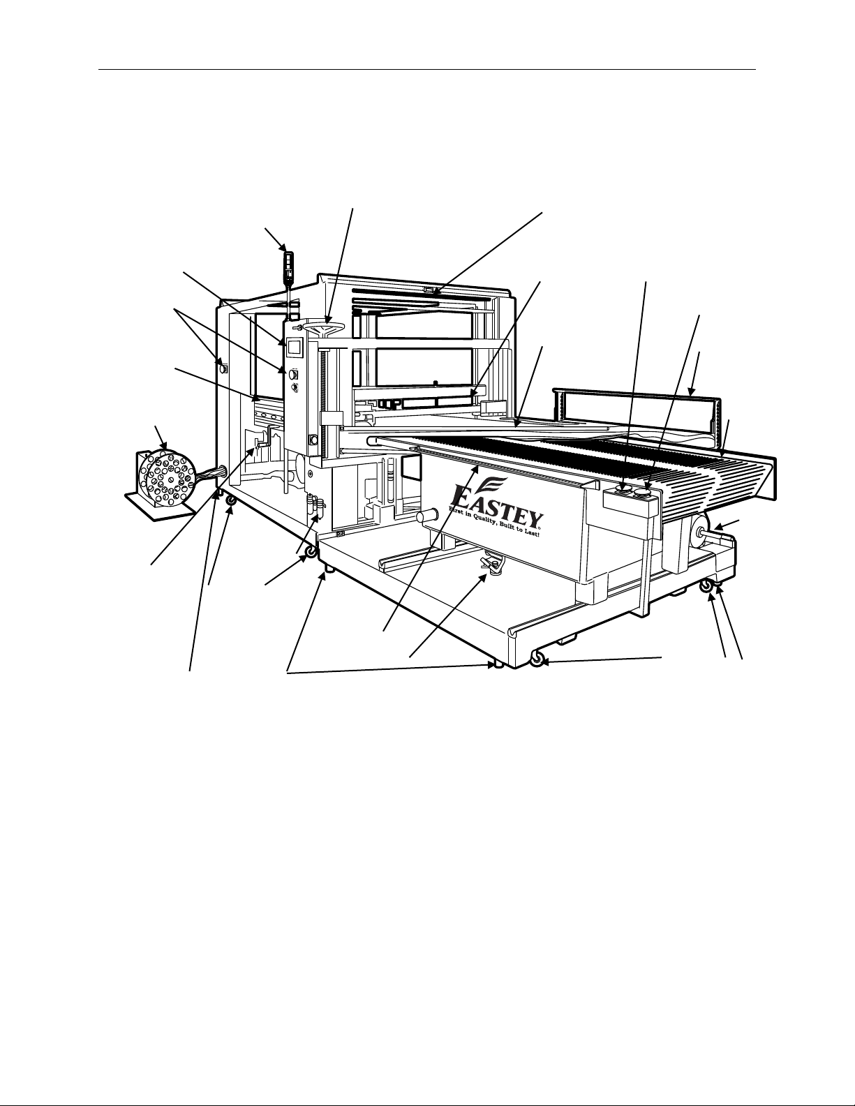
General System Description........................................................................................ 10
Specifications.............................................................................................................. 11
Dimensions ................................................................................................................. 13
Unpacking.................................................................................................................... 14
Loading and Unloading Instructions ............................................................................ 15
Installation ................................................................................................................... 16
Location Requirements ............................................................................................... 16
Moving Units Together and Making Connections........................................................ 18
Connecting Power....................................................................................................... 20
Operation ..................................................................................................................... 21
Machine Controls and Control Panel........................................................................... 21
Other Features............................................................................................................ 23
Setting Temperatures and Timers............................................................................... 25
Setup Screen Settings ................................................................................................ 27
Loading Film................................................................................................................ 29
Setup for Scrap Winding ............................................................................................. 34
Adjusting Package Height ........................................................................................... 35
Running Product ......................................................................................................... 39
Running One Product at a Time.................................................................................. 40
Product Indexing ......................................................................................................... 40
Adjustments ................................................................................................................ 41
Operator’s Panel Screen Adjustment .......................................................................... 41
Fine Tuning the Sealer................................................................................................ 44
Air Regulator Adjustments........................................................................................... 45
Conveyor Tension Adjustment .................................................................................... 46
Seal Head Pressure Adjustment ................................................................................. 47
Scrap Film Take-up Spool Clutch Tension Adjustment............................................... 48
Maintenance ................................................................................................................ 49
Weekly or Monthly Maintenance ................................................................................. 49
Preventative Maintenance for Modular Plastic Conveyor Belts................................... 50
Belt Assembly and Disassembly ................................................................................. 51
Replacing Conveyor Components............................................................................... 53
Replacing Power Film Unwind Components ............................................................... 55
Troubleshooting .......................................................................................................... 57

Appendix A: Electrical Schematics ........................................................................... 64
Appendix B: Temperature Setting Specifications for Shrink-Wrap Plastics.......... 65
Mushroom Insert ......................................................................................................... 65
Appendix C: L-Sealer Size Estimating....................................................................... 66
L-Sealer Center-Folded Film Size Estimating Table ................................................... 66
Warranty Statement .................................................................................................... 67
Customer Support....................................................................................................... 69

Introduction 7
Safety
Read this manual carefully and make it available to everyone connected with the
supervision, maintenance, or operation of this machine. Additional copies are available
on request (Eastey.com/contact-us).
The development of a good safety program that is rigidly enforced is absolutely
imperative when involved in the operation of industrial equipment. Our machinery is well
designed and includes extremely important safety features. Proper installation, safe
operation, and regular maintenance and upkeep are of far greater importance than the
design. Improper operation of this machine can cause injury to operators or bystanders
near the machine and can cause damage to the machine or nearby property. Only
properly-trained individuals following rigidly enforced safety rules, as recommended by
ANSI and OSHA should be allowed to operate these machines.
Be very careful when operating, adjusting, or servicing this equipment. If in doubt, stop
and obtain qualified help before proceeding.
General Safety Precautions
Before installing, operating, or servicing this equipment, please read the following
precautions carefully:
•Always disconnect electrical power before attempting maintenance for any electrical
or moving parts. Do not place hands, head, or any part of the body inside the
confines of the machine unless the mechanism is securely restrained and the
electrical supply is shut off.
•Do not attempt to open or work on the electrical box, junction boxes or other
electrical components of the unit without first disconnecting power to the machine.
Electrical shock hazard exists if power is not disconnected.
•Do not tamper with electrical wiring. Use only the specified power-supply cable. Use
only licensed electricians to check or repair electrical wiring.
•Do not bypass any factory-designed safety features such as guards, interlocks,
switches, etc.
•In order to prevent damage to the machinery or injury to personnel, do not increase
the factory settings on either the electrical or mechanical overload safety devices.
Do not operate a machine if such modifications have been made.
•Never operate this or any moving equipment without all covers and guards in place.
The internal mechanism of most packaging machinery contains numerous shear,
pinch, and in-running nip points, many of which are capable of causing severe injury
and permanent disfiguration.
•Keep hands away from moving conveyors and moving parts. Conveyor belts that
have become worn or frayed can be hazardous and should be replaced promptly.

8Introduction
•Do not stand or climb on any part of the Auto L-Sealer or frame or guards. Never
provide service or attempt to clear a jam when the machine is running.
•To minimize the potential for personal injury, always be sure that the machine
operators and others working on the machinery are properly trained in the correct
usage of the equipment and properly instructed regarding the safety procedures for
operation.
•Heat sealing arms and jaws on packaging machinery can become very hot after a
period of use. Keep hands away while in operation and use caution if the machine
has been running recently. If optional cutting blades have been installed, these can
be very sharp. Exercise caution.
•Do not make any modifications to either the electrical circuitry or the mechanical
assemblies of this machinery. Such modifications may introduce hazards that would
not otherwise be associated with this machinery. Eastey will not be responsible for
any consequences resulting from such unauthorized modification. Do not operate a
machine if any modification has been made.
•This equipment is designed for indoor operation in a typical clean, dry factory
environment. Do not operate the machine in any extremely wet or oily environment
that may exceed operating specifications. Pneumatic equipment requires a clean
and dry supply of air maintained at specified pressure for operation.
•The use of certain types of plastic films in sealing and/or shrink-wrapping equipment
may result in the release of hazardous fumes due to degradation of the film at high
temperatures. Before using any plastic film in this equipment, the manufacturer or
supplier of the film should be contacted for specific information concerning the
potential release of hazardous fumes. Adequate ventilation should be provided at all
times.
•Keep combustible materials away from this equipment. The equipment may be a
source of ignition.
•Do not wear loose clothing such as ties, scarves, jewelry, etc. Long hair should be
pulled back and/or covered while operating this machine.

Introduction 9
Explanation of Symbols
Caution sign or Safety Alert symbol. Indicates caution, be alert, Your
safety is involved. Knowledge of safe operation is required. Caution
indicates a hazardous situation which if not avoided could result in minor
to moderate injury or damage to equipment or property.
Electrical hazard. Indicates electrical danger. Allow only a trained
electrician to open the door or cover of the electrical panel or box. Shut
off electrical power before attempting to open or work in the electrical box,
junction boxes, or other electrical components of the unit.
Ground symbol. Indicates ground. Use Class-3 (lower than 1000) cable
to ground to earth. Incomplete grounding may lead to electrical shock.
Cut or shear hazard. Do not place your hands or any object on the
sealin
g or cutting zone at any time. Shut down the machine before
performing maintenance, parts replacement, or troubleshooting in these
zones.
Pinch hazard. Do not place your hands or any object on the moving
mechanism. Shut down the machine before perfor
ming maintenance,
repair, or adjustment.
Crush hazard. Do not place your hands or any object on the moving
mechanism. Shut down the machine before doing any maintenance,
repair, or adjustment.
High temperature hazard. Do not touch or place hands close to the
heating source to avoid burns. Proceed with any maintenance only when
the temperature of the heater or other heat source has cooled down to
room temperature.
Moisture hazard. Keep equipment dry. This equipment is designed for
indoor operation in a typical clean, dry factory environment, protected
from rain and moisture. Do not operate the machine in any extremely wet
or oily environment that may exceed operating specifications.

10 Introduction
Introduction
General System Description
*Depending on power requirements of your sealer, a main power disconnect switch may be installed on
the other side of the L-Sealer/Exit Conveyor module, not visible from this view.
The Eastey EA Auto L-Sealer Professional Series consists of three main modules,
which may be shipped and moved independently, but which must be aligned and
synchronized to work together when placed in the final working location.
The three main modules of the Eastey EA Auto L-Sealer Professional Series are:
1. The L-Sealer and Exit Conveyor are one unit.
2. The Film Unwinder/Perforator, Infeed Conveyor, and Film Inverter are one unit.
3. The Scrap Uptake Winding Spool is a separate unit.
The Scrap Take-Up Winding Spool, which is shown winding scrap as it feeds out from
the side of the L-Sealer in the above illustration, may be repositioned at the exit end as
an option, in which case an external elbow is installed redirect exiting scrap.
Alarm Signal
Stack Lights
Scrap Film
Take-up
Spool
Conveyor Table
Adjustment Stop
Casters
Casters
Leveling Legs
Filter
Lubricator
Regulator
(Air In)
Film
Roll
Powered Film
Unwind
Inverter Height
Adjustment Wheel
Control
Panel
E-Stop
L-Seal
(Machine
Direction)
L-Seal
(Transverse
Direction)
Film
Inverter Rod
Single Item
and E-Stop
Buttons
Conveyor
Adjustment
Handle
Height
Adjust
Crank
for Scrap
Chain
Photo Emitter (Receiver
is directly below, under
conveyor.)
Leveling
Leg
Infeed
Conveyor

Introduction 11
Specifications
Model
Number
Seal Dimensions
Machine Dimensions Standard Power Net
S
hipping
Front
(F)
Side
(S)
Width
(A)
Height
(B)
Length
(C)
Volts Amps Phase Weight Weight
EA3050T
K
50 in.
127 cm
30 in.
76 cm
86 in.
218 cm
74 in.
187 cm
163 in.
414 cm
220 30/35 1
4600 lbs.
2086 kg
4800 lbs.
2177 kg
E
A3070TK
70 in.
177 cm
30 in.
76 cm
86 in.
218 cm
74 in.
187 cm
183 in.
464 cm
220 30/35 1
5000 lbs.
2267 kg
5200 lbs.
2358 kg
E
A30100TK
100 in.
254 cm
30 in.
76 cm
86 in.
218 cm
74 in.
187 cm
213 in.
541 cm
220 30/35 1
5300 lbs.
2404 kg
5500 lbs.
2494 kg
E
A4050TK
50 in.
127 cm
40 in.
102 cm
86 in.
218 cm
74 in.
187 cm
163 in.
414 cm
220 30/35 1
5100 lbs.
2313 kg
5300 lbs.
2404 kg
E
A4070TK
70 in.
177 cm
40 in.
102 cm
86 in.
218 cm
74 in.
187 cm
183 in.
464 cm
220 30/35 1
5500 lbs.
2494 kg
5700 lbs.
2585 kg
E
A40100TK
100 in.
254 cm
40 in.
102 cm
86 in.
218 cm
74 in.
187 cm
213 in.
541 cm
220 30/35 1
5800 lbs.
2630 kg
6000 lbs.
2721 kg
E
A5050TK
50 in.
127 cm
50 in.
127 cm
96 in.
243 cm
74 in.
187 cm
163 in.
414 cm
220 30/35 1
5600 lbs.
2540 kg
5800 lbs.
2630 kg
E
A5070TK
70 in.
177 cm
50 in.
127 cm
96 in.
243 cm
74 in.
187 cm
183 in.
464 cm
220 30/35 1
6000 lbs.
2721 kg
6200 lbs.
2812 kg
E
A50100TK
100 in.
254 cm
50 in.
127 cm
96 in.
243 cm
74 in.
187 cm
213 in.
541 cm
220 30/35 1
6300 lbs.
2857 kg
6500 lbs.
2948 kg
Voltage and Phase Designator Meaning
Voltage / Phase
Designator
Volts Phase
V1 220 1
Air Supply / Required Air Pressure
Minimum Air
Requirements
3.5 CFM
60 PSI
Explanation of Model Numbers
•E = Manufactured by Eastey Enterprises Inc., division of Engage Technologies.
•A = Automated L-sealer operation. EA model Professional Series L-sealers
incorporate an electromagnetic hold-down system that allows the operator to
load the next package while the preceding package is being sealed, assuring
uniform sealing pressure over the entire length of the seal bars to provide
consistent sealing results.
•_ _ = 30, 40, or 50 — First two digits indicate length of sidebar or nominal
maximum length of side seal in inches: 30, 40, or 50-inch sidebars lengths are
available.
•_ _ or _ _ _ = 50, 70, or 100 — Remaining two to three digits indicate length of
front bar or nominal maximum length of front seal in inches: 50, 70, or 100-inch
front bar lengths are available.

12 Introduction
•T = Takeaway conveyor — Professional Series L-Sealers are typically equipped
with a takeaway conveyor.
•K = Knife — Indicates hot knife seal bar. For smaller units, where (K) is indicated
in parentheses, the hot knife seal bar is an option and the unit can be ordered
with or without it. For larger units, the hot knife seal bar is standard.
•V _ = Voltage and Phase. V1 = 220V AC single Phase. All models are available
configured for 220 VAC single phase. Only single phase is offered.
Standard features
•Designed to seal most polyolefin, polyethylene, and PVC shrink films
•All-welded main frame from ¼-inch cold-rolled steel and ¼-inch 2 × 4 inch tubing
•Soft start infeed and outfeed conveyors
•Variable speed infeed and outfeed conveyors
•Side adjustable film rack for perfect alignment
•Seal head equipped with pneumatic air cylinder for automatic sealing
•Hot knife seal available with mushroom (standard), pancake, or arrow inserts
•Consistent pressure across seal-bar
•Automatic cycle timing with adjustable dwell time
•PLC controlled with product indexing
•Film tracking wheels keep film in place
•Power film unwind ensures proper tension of film
•Multiple pin perforators provide air evacuation
•Power film take-up scrap winder included
•Custom two-part epoxy finish resists scratching
•Heavy duty casters for transportation within plant
•Easy to use design requires minimal training and maintenance
•Side seal size from 30 in., 40 in., or 50 in.; front seal size 50 in., 70in., or 100 in.
•Maximum film width up to 60 inches
•Maximum film roll O.D. up to 12 inches
•60 PSI
•Available in 220V or optional 480V
•Made in the USA

Introduction 13
Dimensions
See Machine Dimensions in Specifications table for overall machine width, height, and
length.
Scrap Take-Up Spool Dimensions
Length
(C)
Width
(A)
Height
(B)
31.75
3.75 Min.
Front View
Top View
Floor
Infeed
Conveyor
Conveyor
Height
35.5 in.
Approx.
L-Seal
Area
Inverter
Bars
Exit
Optional location
for Scrap
Take-Up Spool
Standard location
for Scrap
Take-Up Spool
+ 4 in.
– 0 in.
21.0 in.
27 in.
68.6 cm
24 in.
Ø
Ø61 cm
24 in.
61 cm
24 in.
61 cm
17.5 in.
44.5 cm
53.3 cm
Front/ Side View Side / Front View
Top View

14 Installation
Unpacking
Thoroughly inspect the equipment and packaging immediately on arrival.
The Eastey EA Auto L-Sealer Professional Series consists of three main modules,
which may be shipped and moved independently, but which must be aligned and
synchronized to work together when placed in the final working location.
The three main modules of the Eastey EA Auto L-Sealer Professional Series are:
1. The L-Sealer and Exit Conveyor are one unit.
2. The Film Unwinder/Perforator, Infeed Conveyor, and Film Inverter are one unit.
3. The Scrap Uptake Winding Spool is a separate unit.
Carefully remove the outer protective shipping materials from each module. Inspect
each module of the machine for any damage that may have occurred during transit. If
goods are received short or in damaged condition, it is important that you notify the
carrier’s driver before they leave your company and insist on a notation of the loss or
damage across the bill of lading. Otherwise no claim can be enforced against the
transportation company. Please note that a copy of this document is attached to the
outside of every crate.
If concealed loss or damage is discovered, notify your carrier at once and request,
insist, on an inspection. This is absolutely necessary. A concealed damage report must
be made within ten (10) days of delivery of shipment.
Unless you do this, the carrier will not entertain any claim for loss or damage. The agent
will make an inspection and grant a concealed damage notation. If you give the
transportation company a clear receipt for the goods that have been damaged or lost in
transit, you do so at your own risk and expense.
All claims must be filled within five (5) months of the delivery date or the carrier will not
accept them.
We are willing to assist you in every reasonable manner to help you collect claims for
loss or damage. However, this willingness on Eastey’s part does not make Eastey or its
parent or related companies responsible for collections or claims or replacement of
equipment damaged or lost in transit.

Installation 15
Loading and Unloading Instructions
Air-Ride suspension trailers and ratcheting shipping straps are required for
transportation of the Eastey Auto L-Sealer Professional Series sealers.
When transporting the sealer, roll the machine into the truck or trailer, and then
when the machine is in position for shipping, lower the levelers to just touch the
ground.
Use a shipping ratchet and straps to restrain the sealer securely so it will not shift
in transit.
Use wheel chock blocks at the front and rear of each section to ensure rhe
machine does not move.

16 Installation
Installation
Place the sealer in the desired location with the required electrical power source
available. (See power requirements for the specific model in the Specifications table.)
Make sure the electrical wiring is adequate to provide the required voltage. If the voltage
provided is too low, the equipment will not operate correctly.
Selecting the proper location is one of the most important considerations for initial
setup. When selecting the location, take into consideration the following factors.
1. Adequate clean dry air and power supply nearby?
2. Where is the sealer in relation to the power source?
3. Where is the sealer in relation to the tunnel and any conveyor(s) necessary to
move the wrapped product? (Alignment with packaging line.)
4. Convenience for the operator.
CAUTION! Avoid locating the L-sealer in a cold or drafty area, as heat
may be unintentionally drawn from the sealer and reduce its
efficiency.
If there is any doubt, get qualified assistance with your initial installation.
Location Requirements
When installing the L-sealer please be aware of the following considerations:
1. The surface on which it is located is flat and level.
2. Conveyor or packing table height.
3. Alignment with packaging line.
When the L-sealer is positioned in the operating location you will need access to:
1. Control panel switches: On/Off switch, dwell timer, conveyor timer.
2. Height and width adjustments.
3. Film unwinder.
For units equipped with a takeaway conveyor at the exit of the L-sealer, provision
should be made for exiting packages. For example, a table or bin where packages that
have been sealed will be placed until they can be picked up, or a conveyor that will
move them to the tunnel.

Installation 17
If the L-sealer is part of a longer packaging line, take into consideration the table and
conveyor height in relation to adjacent machinery.
The machine should be placed on a flat, level floor so that it does not rock or move. We
recommend that the machine be securely locked in place when used.
The Eastey EA Auto L-Sealer Professional Series consists of three main modules,
which may be shipped and moved independently, but which must be aligned and
synchronized to work together when placed in the final working location.
The three main modules of the Eastey EA Auto L-Sealer Professional Series are:
1. The L-Sealer and Exit Conveyor are one unit.
2. The Film Unwinder/Perforator, Infeed Conveyor, and Film Inverter are one unit.
3. The Scrap Uptake Winding Spool is a separate unit.
Casters under the larger modules (L-Sealer/Exit Conveyor module and PFU/Infeed
Conveyor/Inverter) allow easy movement over smooth flat surfaces. If you need to lift
one of these large units to move it, you will need to use a pallet jack, floor crane, or fork
lift to move it to its location.
CAUTION! If either of the large modules (L-sealer/Exit Conveyor or
PFU/Infeed Conveyor/Inverter module) must be lifted for
moving, use proper equipment when lifting and moving it to
ensure it is secure and will not shift.
The Scrap Film Take-up Spool module is relatively lighter and equipped with a handle
on top for easy lifting and repositioning.

18 Installation
Moving Units Together and Making Connections
I. Set up the L-sealer/Exit Conveyor module first. Move it to its location, and when it
is in position, use chock blocks to block the casters and secure it from moving.
Adjust the leveling legs to support the unit and so the conveyor surface and seal
heads are level along both the machine-direction axis and transverse-direction
axis.
II. Next, bring the PFU/Infeed Conveyor/Inverter module up next to and in position
with the L-Sealer/Exit Conveyor module. Note that there are attaching flanges
welded to the base of the PFU/Infeed Conveyor/Inverter module, with bolt holes
that must align with bolt holes in the base of the L-Sealer/Exit Conveyor module.
When the unit is in position, use chock blocks to block the casters and secure it
from moving.
L-Sealer
PFU
Inverter
Infeed
Conveyor
L-Sealer
Level
Exit
Clearance
Adequate space for Infeed
Conveyor module
Level
Clearance Adequate clearance for
Power Film Unwind (PFU)
Use leveling feet
at each of four
corners to lift module
off casters and level
sealer and conveyor.

Installation 19
Adjust the leveling legs to support the PFU/Infeed Conveyor/Inverter module and
level the Infeed Conveyor so it is level with the exit conveyor, and also level along
both the machine-direction axis and transverse direction axis. Carefully align holes
in attachment flanges with bolt holes in machine base. Use the bolts provided to
fasten the two sections together.
III. Place the Scrap Film Take-up Spool near the L-Sealer, near where the scrap film
will exit from the L-Sealer. Position the spool in line with exiting scrap film so the
distances will be approximately equal from the scrap film exit to the take-up spool
tensioner, and from the tensioner to the spool hub.
L-Sealer
Fasten Infeed Conveyor
module and L-Sealer module
together.
Move Scrap Take-up Spool
into position and make cable
connections.
Infeed
Conveyor
L-Sealer
Power Film Unwind (PFU)
Use leveling feet
at each of four
corners to lift module
off casters and level
infeed conveyor.
Infeed
Conveyor
Level
Level

20 Installation
Connecting Power
Before bringing power to the unit, electrical cables from the L-Sealer/Exit Conveyor
module must be connected to the PFU/Infeed Conveyor/Inverter module and to the
Scrap Film Take-up Spool module. In each case, the cable originates from the L-
Sealer/Exit Conveyor module and individual wires must be connected to a terminal
block either inside an electrical box attached to the Infeed Conveyor base, or inside the
enclosure which makes up the vertical body of the Scrap Film Take-up Spool module.
For the cable which connects the L-Sealer module to the Infeed Conveyor module,
make sure the locknut for the 90° conduit elbow is on the cable before making
connections.
Infeed Conveyor Electrical Junction Inside Scrap Film Take-up Spool Body
Note: When installing the cable from the L-Sealer/Exit Conveyor
module to the PFU/Infeed Conveyor Inverter module, place
the conduit elbow (provided) onto the cable end, and then
feed it into the side of the electrical box.
A power cord (with optional electrical plug) should be installed by a licensed electrician.
CAUTION! Before operating, ensure the following.
1. All shipping ties are removed.
2. All personnel are clear of the equipment.
3. Electrician has stated that all electrical work is complete.
4. Close all doors or guards securely.
5. Connect air line to regulator and verify 60 PSI, 3.5 CFM.
6. Adjust all controls according to the settings sheet.
Refer to instructions in the Operation section for instructions to power up or shut down
the machine.
L1
Blue
A+
F-
Red
ACCEL
DECEL
EN
CONN1
P2
PWR ON
I1
T
B
F+
A-
CL
L2
P3
MAX
P1
MIN
I2
IR CL
J1 ®
Refer to
Electrical
Schematics
for wiring.
Green wire to ground stud.
Gray wire to
terminal block.
Black wire to
terminal block.
Refer to
Electrical
Schematics
for wiring.
Refer to
Electrical
Schematics
for wiring.
Elbow
Lock
Nut
Cable
This manual suits for next models
9
Table of contents
Other Eastey Industrial Equipment manuals

Eastey
Eastey SB-2 HD User manual

Eastey
Eastey SB-2EX User manual

Eastey
Eastey Value VSA2530TK-V1 User manual

Eastey
Eastey BB-2 User manual

Eastey
Eastey Perfomance EN Series User manual

Eastey
Eastey L-Bar Sealer Tunnel Combo Unit Value Series User manual

Eastey
Eastey TT Series User manual

Eastey
Eastey Perfomance ETB Series User manual

Eastey
Eastey BB-2 SS User manual

Eastey
Eastey Value VSA2530TK-V1 User manual