Eastey SB-2EX User manual

SB-2/3EX
Standard & Stainless
Industrial
Case Taping System
User Guide


SB-2/3EX
Standard & Stainless
Industrial Case Taping System
User Guide
Revised 10/15/2015
P/N 5001680 Rev D
Copyright and Trademarks
Copyright ©2013-2015 Eastey Enterprises
All rights reserved. All trademarks and registered names
are the property of their respective owners.
Eastey Enterprises, Inc.
7041 Boone Ave. N
Brooklyn Park, MN 55428
Phone: (763) 428-4846; Fax (763) 795-8867; 1-800-877-9344
www.eastey.com


Contents:
Safety .............................................................................................................................7
Introduction ...................................................................................................................8
General System Description..........................................................................................8
Specifications................................................................................................................9
Options..........................................................................................................................9
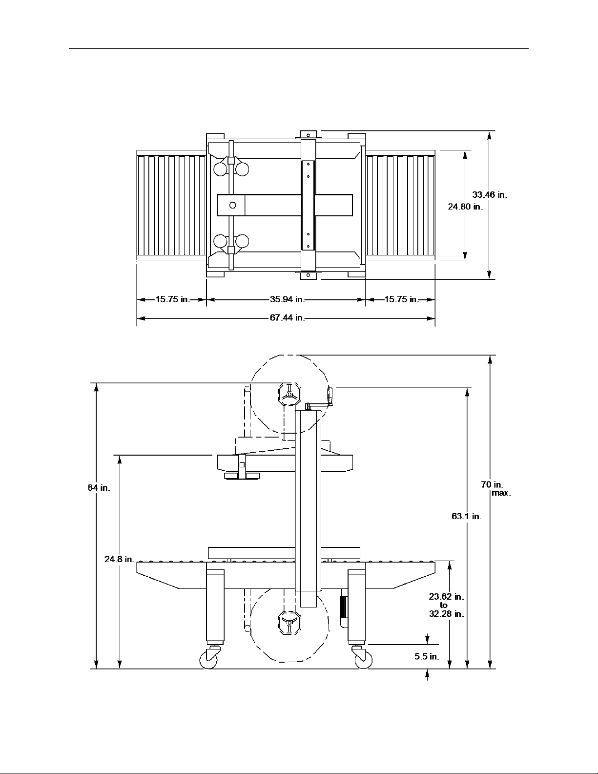
Dimensions .................................................................................................................10
Installation ...................................................................................................................11
Location Requirements ...............................................................................................12
Install Front and Rear Tables......................................................................................13
Next Steps...................................................................................................................13
Operation.....................................................................................................................15
Loading the Tape Cartridges.......................................................................................15
Check Tension............................................................................................................16
Thread Tape................................................................................................................16
Center Tape —Eastey-EX Tape Head only........................................................................18
Main Spring.................................................................................................................18
Power..........................................................................................................................19
Control Panel ..............................................................................................................19
Emergency Stop..........................................................................................................20
Adjustments ................................................................................................................21
Carton Height and Width Adjustments.........................................................................21
Belt Adjustment...........................................................................................................23
Machine Body Height Adjustment...............................................................................23
Maintenance ................................................................................................................25
Rollers.........................................................................................................................25
Cutting Knives.............................................................................................................25
Troubleshooting..........................................................................................................27
Parts List......................................................................................................................29
Electrical......................................................................................................................29
Side Belt Assembly.....................................................................................................33
Side Belt Assembly (Stainless) ...................................................................................36
Vertical Column...........................................................................................................38
Vertical Column (Stainless).........................................................................................41
Machine Body .............................................................................................................43
Machine Body (Stainless)............................................................................................45
Warranty Statement ....................................................................................................47
Customer Support.......................................................................................................49


Safety 7
Safety
Before installing, operating or servicing this equipment, please read the following
precautions carefully:
This machine is equipped with moving belts. Do not place hands near the rear of this
unit when the belts are moving as fingers may be pinched where belts enter the
frame. We suggest the use of a roller-type exit conveyor or pack table for your
cases. Always remove boxes after they clear the exit end of the machine.
Observe caution when near the tape applying cartridges or when threading tape.
The knife is very sharp, automatically operated and is linked to the wipe down
rollers.
Do not attempt to open or work on the electrical box, junction boxes or other
electrical components of the unit without first disconnecting power to the machine.
Electrical shock hazard exists if power is not disconnected.
Do not by-pass any factory-designed safety features such as knife guards,
interlocks, switches, etc.
Do not place hands or body inside the confines of the machine unless the head
mechanism is securely fastened, and the electrical supply is shut off.
Never provide service or clear a box jam when machine is running.
When feeding a box into the unit, always hold down the box top and present the box
to unit. Release hands as soon as the belts begin to take the box.
Do not wear loose clothing such as ties, scarves, jewelry etc. Long hair should be
pulled back and/or covered while operating this machine.

8 Introduction
Introduction
General System Description
Height
Adjustment
Crank
Roller
Table
Control
Panel
Width
Adjustment
Crank
Adjustable
Leg
Drive
Belt
Top
Squeezer
Vertical
Column
Upper
Tape
Head
Casters

Introduction 9
Specifications
Model
SB-2/3EX Standard
Tape
1.5 inches (3.6 cm) or 2 inches (5 cm),
up to 15 inches (36 cm) diameter rolls
Belt speed
75.5 feet/min. (23 m/min.)
Capacity
(L) 4.7 inches (12 cm) to unlimited
(W) 3.9 inches to 19.5 inches (10 cm to 50 cm)
(H) 4.7 inches to 19.5 inches (12 cm to 50 cm)
Power Consumption
450W
Machine size
(L) 68 inches (173 cm)
(W) 33.6inches (85 cm)
(H) 63.1 inches (160 cm) w/o tape head
(H) 70 inches (178 cm with max. tape roll
Machine net weight
353lbs (160kg)
Options
Stainless Steel
3” tape head

10 Introduction
Dimensions
Dimensions are shown in inches.

Installation 11
Installation
Carefully unpack the case taper from the shipping carton.
Remove the shipping bolts that secure the Case Taper to the shipping pallet. Lift the
Case Taper of the pallet.
CAUTION! The SB-2/3EX Standard Case Taper is very heavy and will
require a forklift, floor crane, or several people to move
safely off the shipping pallet. Use proper equipment when
lifting the case taper and ensure the case taper is secure and
will not shift while being moved or during height adjustment
or installation of optional locking casters.
Install the four (4) casters on the Case Taper legs. The casters are very easy to install
simply screw into the threaded holes on the bottom of each leg.
To adjust the leg height, loosen the screws on each leg and slide the insert up or down.
When the leg is at the desired height, retighten the adjustment screws to secure the leg
height.
CAUTION! The case taper must be lifted off the floor to install the
casters. Use proper equipment when lifting or moving the
case taper. Ensure the case taper is secure and will not shift
while installing the casters or adjusting leg height.
Adjustment
Screws
Caster
Brake

12 Installation
The locking casters allow the taper to be moved easily over a smooth flat surface. If the
unit must be lifted to move it to the desired location you will need to use a pallet jack,
floor crane, or fork lift to lift it.
Location Requirements
When installing the SB-2/3EX Standard Case Taper please be aware of the following
considerations:
1. The mounting surface is flat and level.
2. Conveyor or packing table height.
3. Alignment with packaging line.
When the SB 2/3-EX Standard Case Taper is positioned in the operating location you
will need access to:
1. The power switch.
2. Height and width adjustments.
3. Tape loading (Both upper and lower tape cartridges).
Roller tables are provided standard at both the in-feed and exit ends of the case taper.
A packer can fill boxes and close the flaps at the in-feed roller table before feeding
boxes into the case taper, and then pick up boxes that have been sealed from the exit
roller table.
If the case taper is part of a longer packaging line, take into consideration the table and
conveyor height in relation to adjacent machinery.
It is essential that the table and conveyor be at the machine bed height.
The machine should be placed on a flat, level floor so that it does not rock or move. We
recommend that the machine be securely locked in place when used.

Installation 13
Install Front and Rear Tables
Front and rear tables are identical and therefore interchangeable. Temporarily loosen
socket head cap screws at the locations shown in the following illustration. Align the
keyhole slots in the table flanges with the loosened cap screw heads and position the
end table so rollers are level with rollers in the case taper body, then re-tighten cap
screws to secure table. Install one table at each end (front and rear) of the case taper
body.
Next Steps
Follow instructions in the Operation section for instructions to load the tape cartridges in
the upper and lower tape heads.
If tape heads have not been loaded with tape, load the upper and lower tape heads with
tape. (One roll each; follow instructions provided in the Tape Cartridge User Guide.)
Refer to the Adjustments section for instructions to make necessary height and width
adjustments that must be made for operation of the box taper.
Refer to the Operation section for instructions to power up, operate, and shut down the
machine.
Socket Head
Cap Screws
Socket Head
Cap Screws

14 Installation

Operation 15
Operation
Loading the Tape Cartridges
Turn the main power switch to “Off” and disconnect the power.
CAUTION! To avoid personnel injury, remove the tape cartridge before
loading tape.
When handling the tape cartridge be careful to avoid contact
with the tape cutting blade.
After the taping cartridge has been removed push the tape roll onto the tape core
assembly.
NOTE: Make sure the tape roll is pushed all the way on the spindle
assembly.
Tape Roll
Tape Core
Spindle

16 Operation
Check Tension
Check the tape for correct
tension. Tighten or loosen
the tape core holder to adjust
tension.
Thread Tape
Carefully thread the new tape through the rollers in the tape head as shown in the
applicable diagram in the Tape Head User Guide provided with the tape head.
For convenience, diagrams for threading tape in the Eastey-EX Tape Head and EZ-EX
Tape Head are provided on the following page. Follow the diagram that applies for your
tape head, depending on the tape head model and position on the taper.

Operation 17
Eastey-EX Tape Head
EZ-EX Tape Head
Adhesive
Side
Adhesive
Side
Adhesive
Side
Bottom Cartridge
Upper Cartridge
Adhesive
Side
Bottom Cartridge
Upper Cartridge

18 Operation
Center Tape —Eastey-EX Tape Head only
Make sure the tape is centered
on all the rollers.
There are several rollers in the
tape cartridge where the tape
alignment should be checked to
verify the tape stays on center as
it is being dispensed.
Return the tape cartridge to the
operation position.
Main Spring
For sealing light weight boxes, decrease
the main spring tension. For heavier
boxes, increase the main spring tension.
When setting tension for the rollers,
consider the amount of pressure on the
box flaps required to make the seal.
Cartons completely filled to the top with
product may require more pressure on
top and bottom seams when applying
tape than partially-filled cartons, where
excessive pressure could possibly crush
the carton.
Main
Spring

Operation 19
Power
Plug the power supply cord into a properly wired and grounded outlet.
Press start button.
CAUTION! When the power is turned on be aware of moving parts and
belts
Control Panel
When the main power switch is in the “ON” position the power lamp should be
illuminated.
Stop Button (Red)
Press to stop motors and belts.
Start / Run Button (Green)
Press to start motors and belts.
Power Indicator Lamp (White)
On when carton sealer is in operation.
Off when carton sealer is not in operation.
Stop
(Red)
Start / Run
(Green)
Power
Indicator
(White)

20 Operation
Emergency Stop
Emergency Stop Button (Red)
Press the button for emergency stop.
To reset the Emergency Stop button once the emergency
condition has been cleared and it is safe to operate the machine
again, press the Emergency Stop button in while turning it
approximately a quarter-turn in the direction of arrows.
Emergency
Stop Button
(Red)
This manual suits for next models
1
Table of contents
Other Eastey Industrial Equipment manuals

Eastey
Eastey SB-2 HD User manual

Eastey
Eastey Value VSA2530TK-V1 User manual

Eastey
Eastey BB-2 SS User manual

Eastey
Eastey Value VS1620TK User manual

Eastey
Eastey Perfomance EN Series User manual

Eastey
Eastey Perfomance ETB Series User manual

Eastey
Eastey ERX Series User manual

Eastey
Eastey L-Bar Sealer Tunnel Combo Unit Value Series User manual

Eastey
Eastey BB-2 User manual

Eastey
Eastey Combination EC Series User manual