EASTMAN 68-26083 Setup guide


2FormE-522
TheAir Brush Marking System is designed to easily mark
parts during the cutting process to eliminate the time con-
suming step of marking parts before or after cutting. The
markingofpartscanbe usedforparts identification,sewing
lines,mating parts,companylogo's, instructions,etc.Mark-
ing inks are available in a wide variety of colors as perma-
nentandwashableinks.Ifthecoloryourequireisnotshown,
please consult factory.
IMPORTANT
Thepurchasermustinstructalloperatorsontheproperuse
of the equipment. All standard industrial safety measures
andequipment should be provided to protect the operator.
Operatorsmustbecautionedthatimproperorcarelessuse
of this equipment may cause personal injury. If you do not
have qualified operators to instruct new persons, contact
your Eastman sales representative or Eastman factory
direct.
Disconnectelectricalpowersourcebeforeproceedingwith
anyinstallation, adjustment or repair of the Eastman Auto-
mated Cutting System.
Installation
TheAirbrush MarkingSystemisdesign for quick and easy
installationwith optimal performance. Before you begin in-
stallation,please readtheinstructions carefully.Familiarize
yourselfwithall the components required.
1)Disconnectthemainpowerandrelieve airpressure tothe
gantry.
2)Removethe gantrye-chaincoverandthe toolheadcover.
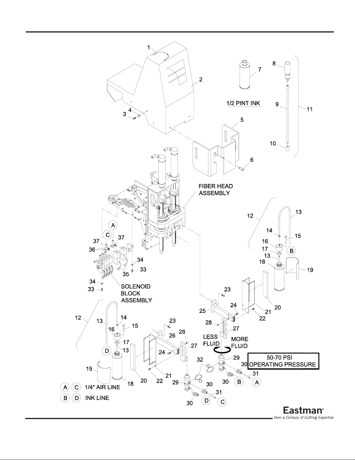
3) Remove and disassembly the solenoid block assembly
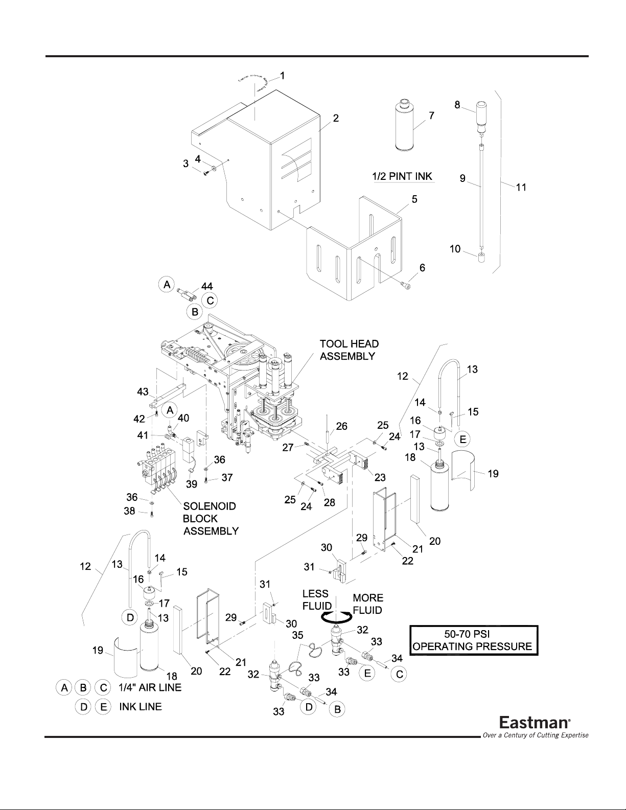
asshownonpage 5. Install the additional solenoid (#36)
with fittings. Mount the complete assembly using the
adapterbar.Connectsolenoidelectrical connector to the
matingconnectoronthe y-axis board (SOL4).
4)Removetheexistinglaserpointermountandreplacewith
the new air brush mounting base as shown on page 5.
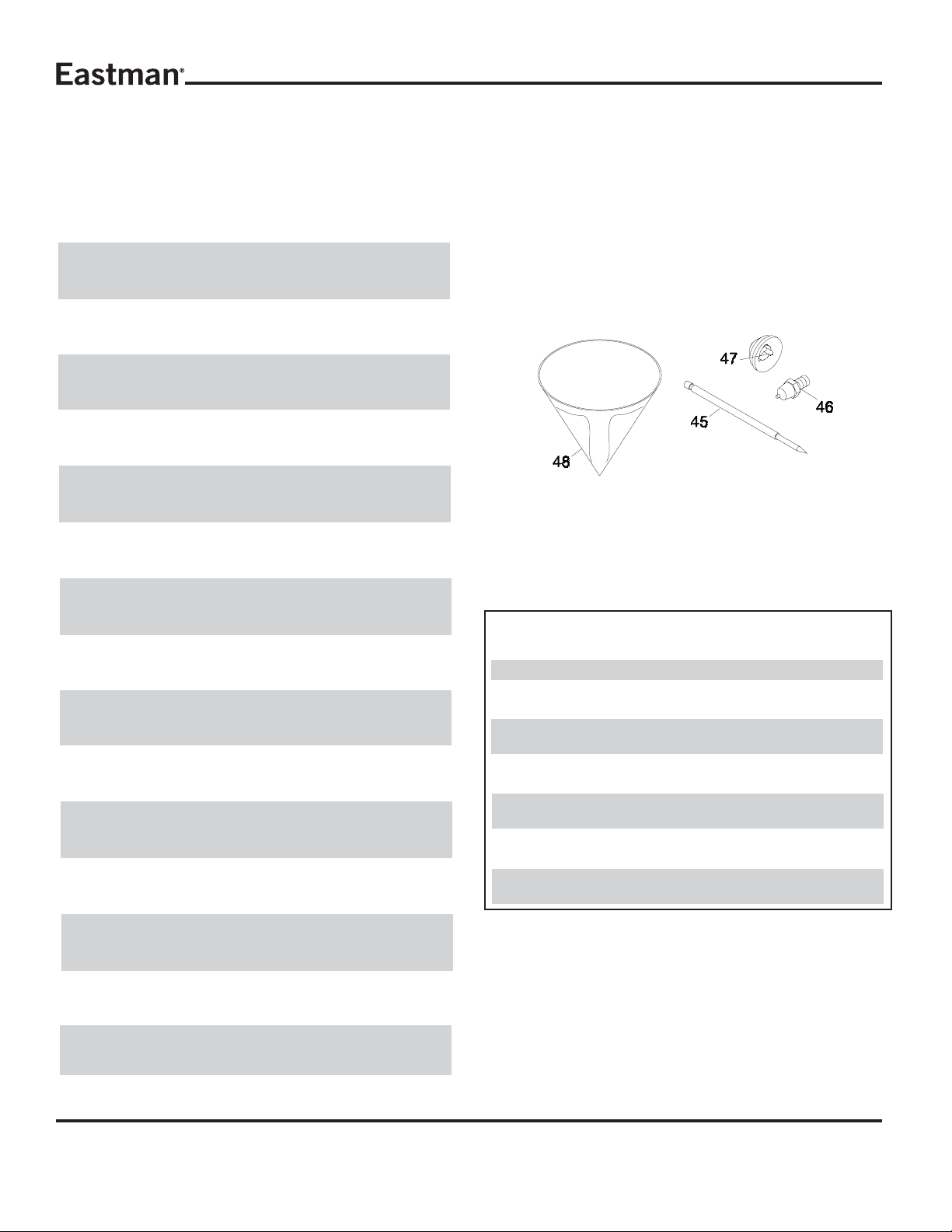
5) Mount the new air brush stylus using the locking band.
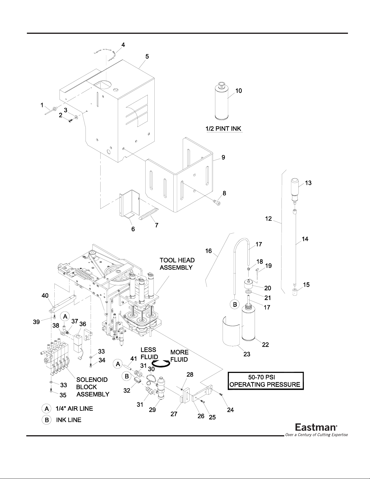
6) Install air line and ink line as shown.
7) Remove the tool guard from the old toll head cover and
installonthenewtoolheadcover.
8) Install new tool head cover. The ink reservoir will slip in
under thetool head cover and intotheholder.
9)Yourairbrushmarkingsystemisnowreadyforoperation.
Operation
WARNING:Spraymaterialsmaybeharmfulifinhaledor
allowed to come into contact with the skin or eyes.
Consult the product label and Material Safety Data
Sheetsuppliedwiththespraymaterial.Followallsafety
precautions. Use in Well Ventilated Area to remove
fumes,dust orover spray.
M a x i m u m A i r P r e s s u r e 1 0 0 P . S . I .
Initial Setup
Set the tool head mount setting to STD 4 Tool.
REF: Log in to easicut to gain access to machine settings.
(User Name: Eastman Password: Eastman*tech).
Select: Options. Select: Machine... . Select: System.
Select Tool Head Type: STD 4TOOL. Select: OK.
SettheTool Mount 4 to down bit 8 (Mount 4 is the airbrush
mount).
REF: Log in to easicut to gain access to machine settings.
(User Name: Eastman Password: Eastman*tech).
Select: Options. Select: Machine... . Select: Tool
Mounts.SelectToolMount:Mount4. Enter8 forDown
Bit setting. Select: OK.
If required, set the offsets and time settings now.
Set theAir Brush tool pressure setting to 70.
REF: Select: Options. Select: Machine... . Select: Tools.
Select Tool: Airbrush. Select Tool Mount: Mount 4. Select
Tool Type: Draw_Tool. Enter 7 for Velocity and 70 for pres-
sure. Select: OK.
Machine Operation
TheAir BrushMarkingSystem isdesignedto operate inthe
same manner as any other tool on the tool head. Create a
file with the cut pattern and marking pattern on separate
layers. Set the marking layer tool mount by drag & drop to
the airbrush tool mount picture. This will set the tool mount
for the marking layer. Remove the air sealing pin from the
ink bottle top, this will help ink flow. The machine is ready
fornormaloperation.

3
FormE-522
Manual Operation
Caution:Thiswill engage the air brush stylusallowing
ink to flow. Marking of material and cut sur-
facemay occur.Protect surfaces asrequired.
TheAir Brush Tool can be turned ON & OFF for setup and
testingpurposes.ToTurntheair brushtool onusingthe UIT
Panel, press Option, press A, press B, and press Enter to
beginspraying.The tool enable On/Off switch canbeused
to turn the tool on and off.
Toturn off this feature, press Option, pressA, press B, and
press Enter .
Note: This feature uses the tool settings from the machine
options menu. Not the layer settings.
Adjustments
Marking line width and density will very depending on the
material.Testing will yield the best results for the following
settings.
Fluid Flow
Locatedontheairbrushstylus,turntheFluidAdjustingKnob
counterclockwise to increase fluid flow and clockwise to
decreasefluidflow.
Stylist Height (1/4" minimum gap)
Toadjustthe stylusheightloosen theair brushmountscrew
andadjustas required.
Velocity (3-7)
Velocity is the speed of the tool when marking. This is set
onthemarkinglayer. Selectthe velocitynumber onthelayer
andtypeinthe desired number.
Air Pressure (60-70 PSI)
Note: The minimum operating pressure of the air stylus is
60 PSI @ 5 scfm during marking. This must be verified us-
ingpressure gaugetool#27-26024
The air pressure is set on the marking layer. Select the air
pressurenumberon the layer and type in thedesiredpres-
sure.
Maintenance
TheAirBrushStylushasbeendesignforminimummainte-
nance. The leather packing washers should be lubricated
once a month with light oil. Old packing washers cause
leakageofairorfluid.
Ink Refill
TheInkReservoir(1/2PintInkBottle)shouldnotberefilled.
Whentheinksupplyrunslow,replacethe1/2pintinkbottle
with a fresh bottle of ink. This will eliminate impurities
clogging the air brush stylus.
Bleeding Air from the Ink Line
With the air brush system installed, place a piece of
nonporous material under the air brush. Remove the air
sealing pin from the ink bottle top. Turn the Tool Enable
switchtoOffposition(Locatedonthegantry).PressOption,
press A, press B, and press Enter to enable air pressure.
TurntheFluidAdjustingKnobcounterclockwisetoincrease
fluidflow and clockwisetodecrease fluid flow.
Spray Tip and Cap replacement.
1.RemoveAir Brush Stylus from tool head.
2.Releaseneedle pressure from the seat of tip, bybacking
offthefluid adjusting nut.
3. Loosen spray cap nut and remove spray cap and spray
tip. Leave Needle in place.
4.Check capandtip size.Install newcapand tip. Note:Use
only matching size cap and tip.
5. Secure Spray Cap nut.
(Continuedon page11)

4FormE-522
Air Brush MarkingAssembly
68-26083 (Triple Tool Head Only)
68-26083-1 (Heavy Duty Tool Head Only)
ITEM PART No. DESCRIPTION QTY
1 546-4-8 1/8"Pop Rivet 2
*2 333-102-8S Screw, Button Hd. #10-32 x 1/2 4
*3 409-99 Finish Washer, #10 4
4 91-26021 Air Brush Decal 1
5 67-26187-2 Cover,TriplewithAir Brush 1
67-26072-1 Cover,Triplew/AirBrush (108") 1
6 67-26327 Bracket, Bottle Holder 1
7 AEC-20-G HoldingSpring 1
*8 54-26393 ShoulderBolt 6
*9 67-26182 ToolGuard 1
*10 SeeChart 1/2 Pint Ink 1
*11 NOTUSED NOTUSED 1
12 70-26025 FluidAdjustmentTool 1
13 70-26027 ToolHandle 1
14 70-26028 14"Adapter 1
15 70-26029 3/8" Socket 1
16 68-26084 InkReservoir, 1/2Pint 1
17 27-02996-3 InkTubing 3
18 67-26348 HoseClamp 1
19 67-26349 SealingPin 1
20 54-26453 Bottle Top, Ink 1
21 65-26023 Bottle Top Seal 1
22 242C1U Ink Bottle 1
*23 91-26020 Decal, Ink Bottle 1
24 333-93-8 Screw, Button Hd. #8-32 x 1/2 2
25 335-93-10 Screw, Socket Hd. #8-32 x 5/8 1
26 67-26323 MountingBase 1
27 67-26322 Air Brush Mount 1
28 211-93 Stop Nut,#8-32 1
29 27-26021 Air Brush Stylus with Fittings 1
30 670-224 LockingBand 1
31 27-26020 1/4"Tube Connector 2
32 27-26023 Shut-offClamp 1
33 410-010 Washer, Flat, #10 2
34 335-102-20 Screw, Socket Hd.
#10-32X1 1/4 1
35 335-102-10 Screw, Socket Hd.
#10-32x5/8 1
36 27-H0382-2 Solenoid,Single Station 1
37 100-13-7 Swivel Elbow,1/4"Tube 1
38 27-H0409 1/8"nptPlug 1
39 335-102-10 Screw, Socket Hd.
#10-32x5/8 1
40 54-26452 Adapter Bar, 6 Station 1
41 27-02996-1 1/4" OD.Air Line 3
Optional Air Brush Components
ITEM PART No. DESCRIPTION QTY
45 27-26022-1 SprayNeedle A/R
46 27-26022-12 SprayTip, Size #3 (.046") A/R
27-26022-10 SprayTip, Size #2 (.040") A/R
27-26022-2 SprayTip, Size #1 (.028") A/R
27-26022-4 SprayTip, Size #0 (.021") A/R
27-26022-6 SprayTip, Size #00 (.018") A/R
27-26022-8 SprayTip, Size#000 (.014") A/R
47 27-26022-13 Spray Cap, Size #3 (.046") A/R
27-26022-11 Spray Cap, Size #2 (.040") A/R
27-26022-3 Spray Cap, Size #1 (.028") A/R
27-26022-5 Spray Cap, Size #0 (.021") A/R
27-26022-7 SprayCap, Size #00 (.018") A/R
27-26022-9 SprayCap, Size#000(.014") A/R
48 67-26588 Filter, Ink A/R
ITEM PART No. DESCRIPTION QTY
42 67-26147-1 HD.ToolHeadCover 1
43 67-26323-1 HD Style Mounting Base 1
44 54-26452-1 Adapter Bar, 4 Station 1
* Not Included inAssembly

5
FormE-522

6FormE-522
DualAir Brush MarkingAssembly
68-26083-2 External Mount (Triple Tool Head Only)
ITEM PART No. DESCRIPTION QTY
1 91-26021 Air Brush Decal 1
2 67-26187-3 Cover,TriplewithDualAirBrush 1
*3 333-102-8S Screw, Button Hd. #10-32 x 1/2 4
*4 409-99 Finish Washer, #10 4
5 67-26182-1 Tool Guard,Triplew/DualExt. 1
*6 54-26393 ShoulderBolt 6
7 See Chart 1/2 Pint Ink 1
8 70-26027 ToolHandle 1
9 70-26028 14"Adapter 1
10 70-26029 3/8" Socket 1
11 70-26025 FluidAdjustment Tool 1
12 68-26084 InkReservoir,1/2 Pint 2
13 27-02996-3 InkTubing 5
14 67-26348 Hose Clamp 2
15 67-26349 SealingPin 2
16 54-26453 Bottle Top, Ink 2
17 65-26023 Bottle Top Seal 2
18 242C1U Ink Bottle 2
*19 91-26020 Decal, Ink Bottle 1
20 211C1-2 FoamTape 1
21 67-26351 External Bottle Mount 2
22 333-93-8S Screw, Button Hd. #8-32 x 1/2 8
23 67-26355 DualAirbrush Mount,Triple, Ext. 1
24 335-93-10 Screw, Socket Hd. #8-32 x 5/8 2
25 404-080 Lock Washer, #8 External 2
*26 81-00002 LaserPointer 1
27 342-86-4 Setscrew, #6-32 x 1/4 1
28 335-93-8 Screw, Socket Hd. #8-32 x 1/2 1
29 335-93-10 Screw, Socket Hd. #8-32 x 5/8 2
30 67-26322 Air Brush Mount 2
31 211-93 StopNut, #8-32 2
32 27-26021 Air Brush Stylus with Fittings 2
33 27-26020 1/4"Tube Connector 4
34 27-02996-1 1/4" OD.Air Line 6
35 670-224 LockingBand 2
36 410-010 Washer, Flat, #10 2
37 335-102-20 Screw, Socket Hd. #10-32 X1 1/41
38 335-102-10 Screw, Socket Hd. #10-32 x 5/8 1
39 27-H0382-2 Solenoid,SingleStation 1
40 100-13-7 SwivelElbow,1/4" Tube 1
41 27-H0409 1/8"nptPlug 1
42 335-102-10 Screw, Socket Hd. #10-32 x 5/8 1
43 54-26452 Adapter Bar, 6 Station 1
44 100-14-7 Y-Port Fitting, 1/4" Push-on 1
* Not Included inAssembly
Optional Air Brush Components
ITEM PART No. DESCRIPTION QTY
45 27-26022-1 SprayNeedle A/R
46 27-26022-12 SprayTip, Size #3 (.046") A/R
27-26022-10 SprayTip, Size #2 (.040") A/R
27-26022-2 SprayTip, Size #1 (.028") A/R
27-26022-4 SprayTip, Size #0 (.021") A/R
27-26022-6 SprayTip, Size #00 (.018") A/R
27-26022-8 SprayTip, Size#000 (.014") A/R
47 27-26022-13 Spray Cap, Size #3 (.046") A/R
27-26022-11 Spray Cap, Size #2 (.040") A/R
27-26022-3 Spray Cap, Size #1 (.028") A/R
27-26022-5 Spray Cap, Size #0 (.021") A/R
27-26022-7 SprayCap, Size #00 (.018") A/R
27-26022-9 SprayCap, Size#000(.014") A/R
48 67-26588 Filter, Ink A/R

7
FormE-522

8FormE-522
ITEM PART No. DESCRIPTION QTY
1 91-26021 Air Brush Decal 1
*2 67-26126 Cover,FiberHead 1
*3 333-102-8S Screw, Button Hd. #10-32 x 1/2 4
*4 409-99 Finish Washer, #10 4
5 67-26148-2 ToolGuard 1
*6 54-26393 ShoulderBolt 4
*7 SeeChart 1/2 Pint Ink 1
8 70-26027 ToolHandle 1
9 70-26028 14"Adapter 1
10 70-26029 3/8" Socket 1
11 70-26025 FluidAdjustment Tool 1
12 68-26084 InkReservoir,1/2Pint 2
13 27-02996-3 InkTubing 5
14 67-26348 HoseClamp 2
15 67-26349 SealingPin 2
16 54-26453 Bottle Top, Ink 2
17 65-26023 Bottle Top Seal 2
18 242C1U Ink Bottle 2
*19 91-26020 Decal, Ink Bottle 1
20 211C1-2 FoamTape 1
21 67-26351 External Bottle Mount 2
22 333-93-8S Screw, Button Hd. #8-32 x 1/2 8
23 335-102-12 Screw, Socket Hd. #10-32 x 3/4 4
24 335-93-10 Screw, Socket Hd. #8-32 x 5/8 2
25 67-26323-3 Right Mount, Ext., Fiber Hd. 1
26 67-26323-4 Left Mount, Ext., Fiber Hd. 1
27 67-26322-1 Air Brush Mount, Extended 2
28 211-93 StopNut, #8-32 2
29 27-26021 Air Brush Stylus with Fittings 2
30 27-26020 1/4"Tube Connector 4
31 27-02996-1 1/4" OD.Air Line 6
32 670-224 LockingBand 2
*33 410-010 Washer, Flat, #10 2
*34 335-102-20 Screw, Socket Hd. #10-32 X1 1/4 2
35 27-H0382-2 Solenoid,Single Station 2
36 27-H0409 1/8"nptPlug 2
* Not Included inAssembly
Optional Air Brush Components
ITEM PART No. DESCRIPTION QTY
45 27-26022-1 SprayNeedle A/R
46 27-26022-12 SprayTip, Size #3 (.046") A/R
27-26022-10 SprayTip, Size #2 (.040") A/R
27-26022-2 SprayTip, Size #1 (.028") A/R
27-26022-4 SprayTip, Size #0 (.021") A/R
27-26022-6 SprayTip, Size #00 (.018") A/R
27-26022-8 SprayTip, Size#000 (.014") A/R
47 27-26022-13 Spray Cap, Size #3 (.046") A/R
27-26022-11 Spray Cap, Size #2 (.040") A/R
27-26022-3 Spray Cap, Size #1 (.028") A/R
27-26022-5 Spray Cap, Size #0 (.021") A/R
27-26022-7 SprayCap, Size #00 (.018") A/R
27-26022-9 SprayCap, Size #000 (.014") A/R
48 67-26588 Filter, Ink A/R
DualAir Brush MarkingAssembly
68-26083-3 External Mount (Fiber Tool Head Only)

9
FormE-522

10 FormE-522
Optional Components
GRAVITY FEED RESERVOIR
(1/2 Pint)
68-26084-1
ITEM PART No. DESCRIPTION QTY
1 100-18-29 PressureGauge,0-100PSI 1
2 100-14-10 Tee Fitting, 1/8"npt, 1/4" Tube 1
3 27-02996-1 1/4" OD.Air Line 1
AIR GAUGE TOOL
27-26024
ITEM PART No. DESCRIPTION QTY
1 67-26349 SealingPin 1
2 54-26453-3 BottleTop,Ink, Gravity Feed 1
3 65-26023 Bottle Top Seal 1
4 100-17-7 Bottle Fitting, Gravity Feed 1
5 54-26484 InkBottle, Gravity Feed 1
6 67-26348 HoseClamp 1
7 27-02996-3 InkTubing 1

11
FormE-522
•Stylus should never be closer than 1/4" from material.
Thiswillobstructairflowcausinginktobuilduponthe
cap. Wipe cap clean.
•TheVentholeintheinkreservoirshouldbeclosedwiththe
sealing pin when not in use. If the vent hole is not
sealed, the ink will thicken and may cause airbrush
clogging.
•If refilling the in reservoir from gallon containers, the ink
reservoir should be drained and cleaned out periodi-
cally.(dependentinkusage).Thiswillhelpavoidthick
sediment from forming at the bottom of the ink reser-
voir.Alwaysusepaintfilter#67-26588whenfillingpaint
reservoir.
Trouble Shooting
Problem Solution
Noink flow a.Increasefluidflow
b. Dirty cap, wipe stylus cap clean
c.No ink, replace ink and bottle
d.Breatherholepluggedincap
e.Verifyoperatingairpressure
f. Vacuum leak, check fittings
Littlefluid flow a.Increase fluidflow
b.Decrease velocity
c.Breather hole plugged incap
Excess fluid a.Decrease fluidflow
b.Wornpackingwashers
c.Incorrect needlegroovesetting
FluidLeak a.Check ink line fittings
b. Ink line connected to wrong
fitting
Inconsistent pattern a.Wipe clean stylus cap
b.Clean stylus
c.Breather hole plugged incap
Fuzzy lines a.Increase fluidflow
b.Slowvelocity
c. Lower stylus height
Wetpattern a.Decrease fluidflow
b.Increase velocity
c Incorrectneedle groovesetting
AB Function a. Set Pointer tool type to No_Tool
notworking
Needle Removal
1.RemoveAir Brush Stylusfrom tool head.
2.Releaseneedle pressure from the seat of tip, bybacking
offthefluid adjusting nut.
3.RemovetheRearCap Assembly.
4.Usingapairofpliers,griptheNeedlePistonAssemblynut
and pull the assembly out.
5. Loosen the needle chuck and slide needle out.
6. Replace needle to desired position and secure needle
chuck.
7.Reassembleinreverseorder.
Needle Setting
Inkshouldbemixedthoroughlyandalwaysstrainedthrough
a lint free cloth or fine mesh strainer before using.
The Needle-Piston Assembly has a needle chuck which
lockstheneedleinposition.Thesinglegrooveontheshank
of the needle indicates location at which to lock the piston.
Lockpistonslightlybelowmarkforusewithveryheavyfluids
andslightlyabovemark(nearerbluntend)forlightfluids.
Example: Eastman MP style ink requires the groove to be
completelycovered.
Cleaning
Flush clean solvent through the fluid passage of the stylist
andwipeofftheoutsidewithcleansolvent.Neverleavethe
entirestylistimmersedinsolvent.Dirtyspraycapsandtips
shouldbecleanedbysoakinginsolventandblowncleanwith
air.
Note:Neverusewireorsharpinstrumentstocleanportsas
permanentdamagemayoccur.
Helpful Hints
•Alwayskeepmaterialunderairbrushstyluswhenmarking.
This will help keep your table surface clean and free
fromink.
•Begin each day by marking a short pattern an scrap
material.Thiswillcleanthestylusandbringinktothe
stylus for future use.
•Endeachdaybymarkingashortpatternonscrapmaterial.
This will clean the stylus.
•Shake ink well before use.
Thiswillallowthecolorpigmenttomixandgiveaeven
colorwhenmarking.

This manual suits for next models
3
Table of contents
Popular Airbrush manuals by other brands

REVELL
REVELL 39196-0388 Instruction

Cocraft
Cocraft HS-28PSK Original instructions

Conrad
Conrad Hobby Airbrush K3 operating instructions

Silvercrest
Silvercrest SRWB 1000 A1 operating instructions

Central Pneumatic
Central Pneumatic 95923 Owner's manual & safety instructions

Parkside
Parkside PABK 60 A1 Operation and safety notes