Easy Travel Elite User manual

Elite
Service Manual

EasyTravel Elite – ET1E – Service Manual Rev. 0404 2

EasyTravel Elite – ET1E – Service Manual Rev. 0404 3
Table of contents:
1. System components and details 5
2. Annual maintenance service 6
3. Spare parts replacement 7
4. Programming 52
5. Fault finding 54
6. Electrical wiring 55
7. Charger 56
8. Spare parts 57
9. List of Tool Types 59
NOTE: Design details may change without notice

EasyTravel Elite – ET1E – Service Manual Rev. 0404 4

EasyTravel Elite – ET1E – Service Manual Rev. 0404 5
1. SYSTEM COMPONENTS AND DETAILS
1.1 EasyTravel Elite parts – (Figure 1)
1. Battery pack (detachable)
2. Front column (detachable)
3. Column lock/release triggers
4. Controller cover
5. Charging socket (Fig. 1A)
6. Front drive wheels
7. Foot platform
8. Seat shell
9. Seat cushions
10. Foldable Armrests
11. Rear wheel
12. Folded frame lock pin
13. Platform bottom lock pin
14. Utility basket (holding capacity
9kg)
15. Charger and connecting cables
(Fig. 1B).
16. Control Panel
17. Freewheel switch
1.2 Control Panel – Figure 2
1. Switch
2. Hand control lever (right and left)
3. Speed adjusting knob
4. Indicator light (LED)
5. From serial # and onwards: Bat-
tery Level Indicator
6. Hand-grips
BELL: If the user requires an audible warn-
ing device, a standard bicycle bell can be
attached to the handlebar.

EasyTravel Elite – ET1E – Service Manual Rev. 0404 6
2. SERVICE
For reasons of safety and the prevention of accidents caused by wear which is not detected in time, the
EasyTravel Elite should be tested and serviced once a year. All safety-related components of the Easy-
Travel Elite should be checked and serviced, safety and functional tests should be performed. It is important
to detect initial wear in time and to use exclusively original spares, or such parts that were authorized by the
manufacturer.
Test the following maintenance items:
The components of the EasyTravel Elite frame for overload and initial cracks.
Wear of tire on wheel.
All screws and attachments for safe securing, cable connections for wear, and the mechanisms of
the EasyTravel Elite for correct functioning.
The proper functioning of the electronic system and brakes.

EasyTravel Elite – ET1E – Service Manual Rev. 0404 7
3. SPARE PARTS REPLACEMENT
3.1 Control Panel Assembly
Kit Number E0-00-1-202
Tools:
Phillips #2 Screwdriver
1. Open Screws (3-A) and remove top and
bottom Control Panel Cover (3-B, C)
2. Disconnect the Control Cable (3-D)
3. Open Screws (3-E) and remove Control
Panel (3-F)
4. Secure new Control Panel (3-F) with
Screws (3-E)
5. Connect the Control Cable (3-D) to Con-
trol Panel (3-F)
6. Secure top and bottom Control Panel
Cover (3-B, C) with Screws (3-A)
7. Check all Control Panel functions: indi-
cation, drive, brake and speed control
Figure 3

EasyTravel Elite – ET1E – Service Manual Rev. 0404 8
3.2 Handgrip pair
Kit number E0-00-1-070
Tools:
Silicone spray
Phillips #2 Screwdriver
1. Remove Control Panel Assembly, see
instructions 3.1
2. Remove the Handgrips (4-A)
3. Spray Handlebars (4-B) of the Column
Frame and inside of the new Handgrips
lightly with Silicone Spray and push
them onto the Column Frame
4. Reassemble Control Panel Bottom
Cover and Control Panel Assembly
5. Push the Handgrips back over both Cov-
ers
NOTE: Check that Handgrips do not slide off
of Covers easily – this can cause a safety
hazard if control lever gets caught under
Handgrip edge. Remove excess silicon if
needed.
Figure 4

EasyTravel Elite – ET1E – Service Manual Rev. 0404 9
3.3 Controller Cover
Kit Number E0-00-1-034
Tools:
Phillips #2 Screwdriver
1. Remove Screws (5-A) at the top and
bottom of the Controller Cover (5-B) and
remove Cover
2. Disconnect Connector (5-C) from Inter-
face Circuit Board (5-D)
3. Check that the solder tabs of the Free-
wheel Switch on new Cover are bent
apart
4. Insert Connector of new Cover (5-C) to
Interface Circuit Board
5. Secure the Cover on the Column
NOTE: Ensure that the Power Cable is
routed under the Controller (see Figure
10) and that it will not be pinched when
closing and securing the Cover
6. Check drive, brake and freewheel op-
eration
Figure 5

EasyTravel Elite – ET1E – Service Manual Rev. 0404 10
3.4 Controller
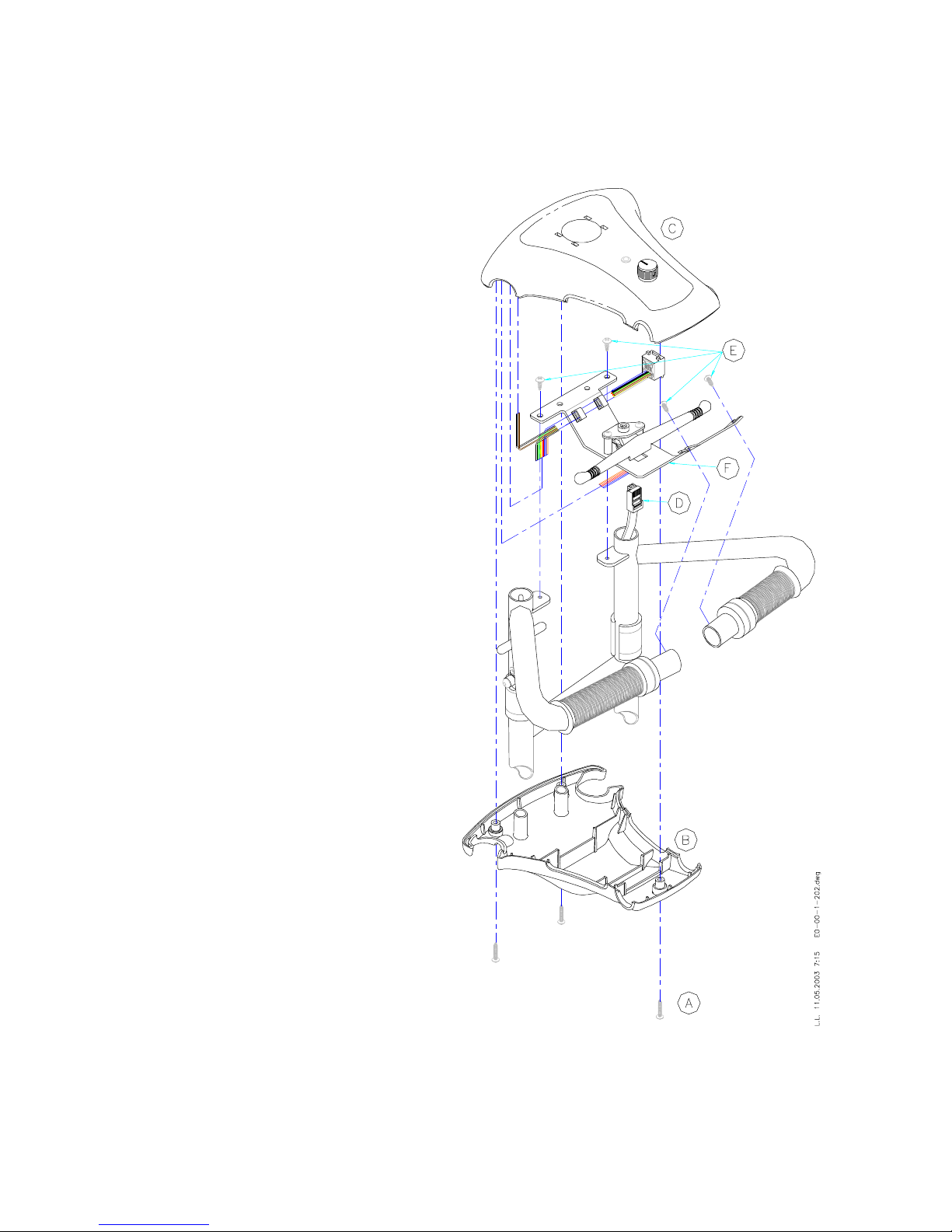
Kit Number E0-00-1-032 (Solo Controller) Figure 6
Kit Number E0-00-1-115 (S-Drive Controller) Figure 7
Tools:
Short Phillips #2 Screwdriver
Pliers
REMARK: The S-Drive controller can be fit-
ted on a unit that originally was issued with a
Solo controller; this will require a new Inter-
face Circuit Board, E0-00-1-116
1. Remove Controller Cover, see instruc-
tion 3.3
2. Detach wiring from Controller (6a-A)
3. Remove Controller (6a-A) by unscrew-
ing Screws (6a-B)
4. Secure new Controller to Column Frame
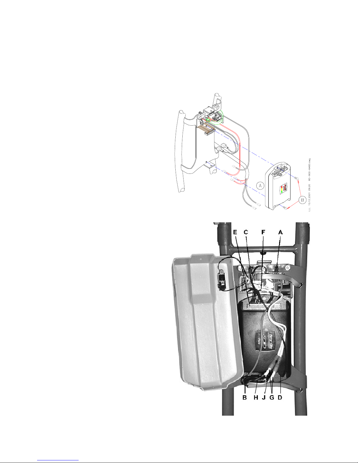
5. Attach Wires to Controller (Fig. 6b): from
Battery Contacts Assembly, the red wire
(A) to “B+” tab (B), the black (C) to “B-“
tab (D); from Interface Circuit Board in-
sert 11-pin connector into top socket P2
(E); the two white wires (F) to the white
capped cables (G) from Power Cable;
from Power Cable the #1 wire to “M+”
tab (H), the #2 to “M-“ tab (J)
6. Secure Controller Cover to Column
Frame
7. Check drive, brake and freewheel op-
eration
Figure 6b
Figure 6a

EasyTravel Elite – ET1E – Service Manual Rev. 0404 11
Kit Number E0-00-1-115 (S-Drive Controller)
Tools:
Phillips #2 Screwdriver
Pliers
REMARK: The S-Drive controller can be fit-
ted on a unit that originally was issued with a
Solo controller; this will require a new Inter-
face Circuit Board, E0-00-1-116
1. Remove Controller Cover, see instruc-
tion 3.3
2. Detach wiring from Controller (7a-A)
3. Remove Controller (7a-A) by unscrew-
ing Screws (7a-B)
4. Secure new Controller to Column Frame
with Screws (7b-A)
5. Attach Wires to Controller: from Battery
Contacts Assembly (E): the red wire to
“B+” tab, the black to “B-“ tab; the Con-
nector from the Interface Circuit Board
(B); the two white wires (C) to the white
and green/yellow cables from Power
Cable (C); from Power Cable (D) the red
wire to “M+” tab, the black to “M-“ tab
6. Secure Controller Cover to Column
Frame, ensure that no wires will be
pinched or damaged by the Cover or the
Screws
7. Check drive, brake and freewheel op-
eration
Figure 7a
Figure 7b

EasyTravel Elite – ET1E – Service Manual Rev. 0404 12
3.5 Battery Contacts
Kit number E0-00-1-059
Tools:
Phillips #2 Screwdriver
1. Remove Controller Cover, see instruc-
tion 3.3
2. Disconnect wiring to Controller (8-A) and
Interface Circuit Board (8-B)
3. Unscrew Screws (8-C) and remove Bat-
tery Contacts Assembly (8-D)
4. Secure new Battery Contacts Assembly
(8-D) with Screws (8-C)
5. Connect Wiring (8-A) to Controller (red
to “B+” tab, black to “B-“ tab), Connector
(8-B) onto Interface Circuit Board
6. Reassemble Controller Cover, see in-
struction 3.3
7. Check drive, brake and freewheel op-
eration
Figure 8

EasyTravel Elite – ET1E – Service Manual Rev. 0404 13
3.6 Interface Circuit Board ET1B
Kit number E0-00-1-058 (for Solo controller) (for serial # up to 12000401999)
Kit Number E0-00-1-116 (for S-Drive controller) (from serial # 12000402001onwards)
Tools:
Phillips #1 Screwdriver
Phillips #2 Screwdriver
1. Remove Controller Cover, see instruc-
tion 3.3
Solo:
2. Disconnect Control Cable (9a-A), wiring
to Controller (Fig. 9a-B), Contact Pins
Assembly (9a-C) and Power Cable (9a-
D)
3. Unscrew 3 Screws (9a-E) and remove
Interface Circuit Board (9a-F)
4. Secure new Interface Circuit Board (9a-
F) with Screws (9a-E)
5. Connect Control Cable (9a-A), wiring to
Controller (9a-B), Contact Pins Assem-
bly (9a-C) and Power Cable (9a-D)
S-Drive:
2. Disconnect Control Cable (9b-A), wiring
to Controller (Fig. 9b-B) and Contact
Pins Assembly (9b-C)
3. Unscrew 3 Screws (9b-D) and remove
Interface Circuit Board (9b-E)
4. Secure new Interface Circuit Board (9b-
E) with Screws (9b-D)
5. Connect Control Cable (9b-A), wiring to
Controller (9b-B) and Contact Pins As-
sembly (9b-C)
6. Reassemble Controller Cover
7. Check drive, brake and freewheel op-
eration
Figure 9a
Figure 9b

EasyTravel Elite – ET1E – Service Manual Rev. 0404 14
3.7 Control Cable
Kit number E0-00-1-054
Tools:
Phillips #2 Screwdriver
1. Open Control Panel Cover, see instruc-
tion 3.1
2. Open Controller Cover, see instruction
3.3
3. Disconnect Control Cable from Control
Panel (3-C) and Interface Circuit Board
(9-A)
4. Remove Control Cable
5. Insert new Control Cable (if needed, re-
move the Paint Protector and replace it
with a new one after the Control Cable is
inserted, see instruction 3.32)
6. Connect Control Cable to Control Panel
and Interface Circuit Board
7. Reassemble Controller Cover and Con-
trol Panel Cover, see instructions 3.1
and 3.4
8. Check all Control Panel and Controller
functions: drive, brake, speed and indi-
cation

EasyTravel Elite – ET1E – Service Manual Rev. 0404 15
3.8 Power Cable to Motor ET1E
Kit Number E0-00-1-209
Tools:
Allen Key 3 mm
1. Remove the Slot Cover, see instruction
3.8
2. Disconnect Power Cable from Hub Mo-
tor, see instruction 3.9
3. Remove Controller Cover, see instruc-
tion 3.3
4. Detach the Wires from the Controller
(11-A) and Interface Circuit Board (11-B)
5. Carefully pull the Power Cable out of the
Column Frame
6. Thread the new Power Cable from the
Controller-end into the hole in the Col-
umn Frame out of tube and inside the
Fork Assembly, as shown in Fig. 10
7. Connect the #1/red insulated Wire end
to positive/red colored Terminal, the
#2/black insulated Wire end to nega-
tive/black Terminal, the #3 and green
Wire to white Wires from electromag-
netic Brake
8. Fit connectors in tube and secure Slot
Cover over tube
9. Attach from the Power Cable the black
insulated #1 Wire End to “M+” tab, the
red insulated #2 to “M-“ tab on Controller
and the two white insulated Wire Ends
to the Wires from Interface Circuit Board
10. Secure Controller Cover to the Frame,
ensure that no wires will be pinched or
damaged by the Cover or the Screws
11. Check drive, brake and freewheel func-
tion
Figure 10
Figure 11

EasyTravel Elite – ET1E – Service Manual Rev. 0404 16
3.9 Hub Motor
Kit Number E0-00-1-208
Tools:
Allen Key 3 mm
Allen Key 5 mm
Allen Key 6 mm
Loctite Adhesive
1. Open Screws and Spring Washers (12-
A)
2. Remove Slot Cover (12-B)
3. Detach Power Cable (12-C) from Hub
Motor (12-E)
4. Remove the Screws (12-D) securing the
Hub Motor to the Fork Assembly
5. Apply Loctite to the Screws (12-D) and
secure with them the new Hub Motor
(12-E) to the Fork Assembly
6. Attach Power Cable (12-C) to Hub Mo-
tor, see instruction 3.10
7. Apply a drop of Loctite to Screws (12-A)
8. Secure Slot Cover (12-B) with Spring
Washers and Screws (12-A)
9. Check drive, brake and freewheel func-
tion
Figure 12

EasyTravel Elite – ET1E – Service Manual Rev. 0404 17
3.10 Fork Assembly
Kit Number E0-00-1-038
Tools:
Allen Key 3 mm
Allen Key 5 mm
Allen Key 6 mm
Wrench, open end 13 mm
Wrench, open end 19 mm
Torque Wrench
Loctite Adhesive #242 (1312)
1. Remove Hub Motor, see instruction 3.9
2. Remove “Nylock” Lock Nut (13-A) and
Screw (13-B)
3. Slide Fork Assembly (13-C) from Col-
umn Frame (13-D)
NOTE: Ensure that the Column Release
Pin (13-E) is withdrawn before removing
and replacing the Adapter Block
4. Slide new Fork Assembly (13-C) in the
Column Frame
5. Insert Screw (13-B) and secure it with
“Nylock” Lock Nut (13-A)
6. Secure Hub Motor to Fork Assembly,
see instruction 3.9
7. Remove Screw (14-A) holding Pin (14-
B)
8. Remove the Pin from the new Quick Re-
lease Mechanism, apply some Loctite in
the thread and position it under the
Conical Cap (14-C)
9. Secure the Pin (14-B) to the Cap with
Screw (14-A) using a torque wrench,
torque to 40 N-m.
Figure 13
Figure 14

EasyTravel Elite – ET1E – Service Manual Rev. 0404 18
3.11 Column Release Cable Kit
Kit Number E0-00-1-080
Tools:
Phillips #2 Screwdriver
Wrench, open end 8 mm
Allen key 3 mm
Wire Cutter
Pliers
Crimp Tool
Loctite Adhesive # 496 (3854)
Light grease/lubricant
1. Remove Control Panel Cover, see in-
struction 3.1
2. Remove Cable End Cone, Vinyl Caps
and Screws (2x) and open Cable Locks
3. Slide Release Bushing out of Column
Frame and remove Cable with Lock Pin
and Spring
4. Thread Column Lock Pin (15-A) and
Spring (15-B) onto the Column Lock Pin
Cable (15-C)
5. Thread the Cable through the large hole
in Connecting Plate (15-D), Column
Lock Pin Housing (15-E) and the small
hole in Connecting Plate (15-F)
6. Apply some lubricant to Lock Pin (15-A)
7. Thread the Cable Guide (15-G) onto the
Cable and thread the cable into the Ca-
ble Guide Adjustable Stop (15-H) and
through the Tube of Column Frame (15-
J)
8. Thread the Release Bushing (15-K) with
the threaded hole down onto the Cable
making sure that the Cable passes
through the two Cable Locks (15-L).
Bring the Release Bushing (15-K) to its
approximate position and lightly secure
it with the Cable Locks (15-L)
Fi
g
ure 15

EasyTravel Elite – ET1E – Service Manual Rev. 0404 19
9. Apply Loctite to Screw (15-N) and se-
cure Column Latch Bushing (15-M) with
it onto Release Bushing (15-K)
10. Take up the slack in the Cable (15-C) so
that the end of the Column Lock Pin (15-
A) is flush with the outside of Connect-
ing Plate (15-D)
11. Release the two Cable Locks (15-L) and
bring the Release Bushing (15-K) to its
final position, Latch Bushing (15-M)
reaching the bottom of slot in Column
Frame Tube (15-J). Tighten the two Ca-
ble Locks (15-L)
12. Place the two Set Screws (15-P) in the
upper threaded holes of the Release
Bushing (15-K) and slide the two Vinyl
Caps (15-Q) onto them.
NOTE: do not over-tighten the Screws
(15-P) against the Cable.
13. Trim Cable to approximately 25 mm. (1")
beyond the end of the Column Frame
Tube. Crimp the Cable End Cone (15-R)
onto the end of the Cable.
14. Test the function of the Column Lock Pin
Assembly and adjust as necessary.
15. Fold Frame with Column attached to it,
ensure the short pin (15-N) slides over
the frame latch without forcing it and
holds the frame in a latched position.
16. Release the latch, ensure the short pin
(15-N) releases over the frame latch
crown without jamming (low effort)

EasyTravel Elite – ET1E – Service Manual Rev. 0404 20
3.12 Protector Roller Kit
Kit Number E0-00-1-081
Tools:
Allen Key 5 mm
Loctite Adhesive # 242 (1312)
1. Open Cap Nut (16-A), remove Threaded
Rod (16-B) and Roller (16-C)
2. Place the new Roller (16-C) between the
two Plates (16-D) and align with holes
3. Insert Threaded Rod (16-B) though the
holes and Roller and right hand Plate
4. Apply a drop of Loctite to the Cap Nut
(16-A) and screw it onto the Rod (16-B);
avoid excess spill of Loctite which may
lock the Roller
5. Ensure that the assembly is not over-
tightened and that the Roller can rotate
freely Figure 16
Table of contents
Popular Mobility Aid manuals by other brands

TOPRO
TOPRO Troja Walker2 Instructions for use

Lumex
Lumex ConTour RJ4402 Series Instructions & warranty information

aidapt
aidapt Linton Mobile Commode Series Fixing and maintenance instructions

Arjo
Arjo MLA4060 Instructions for use

EasyStand
EasyStand 5000 YOUTH owner's manual

EasyCare
EasyCare Oxford User instruction manual