EasyPro Eco-Clear EC2600 Use and care manual

1
EC2600 • EC2600U • EC3900 • EC3900U
How does the
Eco-Clear
Pressure Filter work?
These lters receive dirty water from the
pump and return sparkling clear water to your
pond. The EasyPro pressure lter is ideal for
pond keepers who want simplicity, clear water
and an attractive, hidden lter system.
Eco-Clear
Pressurized Filter
with Cleaning Indicator and Backwash Feature
Instructions for Operation • Safety • Warranty

2
Pressure Filter Installation
Please read all instructions carefully and keep for future reference
Safety and Electrical Connections
• Always disconnect the electrical supply before starting to handle, maintain, repair
or install any pond equipment.
• This product is not submersible, and it must be situated where it cannot fall into the water.
However, the design is weather resistant, and EasyPro Eco-Clear lters can safely be
installed outdoors.
• Direct exposure to ultraviolet light can damage eyes and skin. Do not attempt to
view the lamp when lit.
•
Connect UV units only to a receptacle protected by a Ground Fault Circuit Interrupter. (GFCI)
• Protect from the frost. In freezing climates, drain the lter and remove from the ground and
store in a warm dry place to avoid damage caused by ice.
• All electrical work must be performed by a qualied technician. Always follow the National
Electrical Code (NEC) or the Canadian Electrical Code as well as all local, state and
provincial codes. Code questions should be directed to your local electrical inspector.
Failure to follow electrical codes and OSHA safety standards may result in personal injury
or equipment damage. Failure to follow manufacturer’s installation instructions may result
in electrical shock, re hazard, personal injury or death, damaged equipment, provide
unsatisfactory performance and may void manufacturer’s warranty.
Installation of the Eco-Clear Pressure Filter
1. The EC2600U and EC3900U come with the UV light already installed.
2. Position pump at the furthest point from the waterfall for best circulation. Run the tubing
out of the pond to the lter. Bury or conceal the tubing as desired.
3. Solids handling Eco-Clear pumps work well with the Eco-Clear Filters.
4. Position the pressure lter anywhere around the pond. Avoid placing the lter where it
could get ooded or fall into the pond. Since the discharge is under pressure, the lter
can be located downhill from the waterfall. For units with UV lights, be sure the power
cord can reach your outlet.
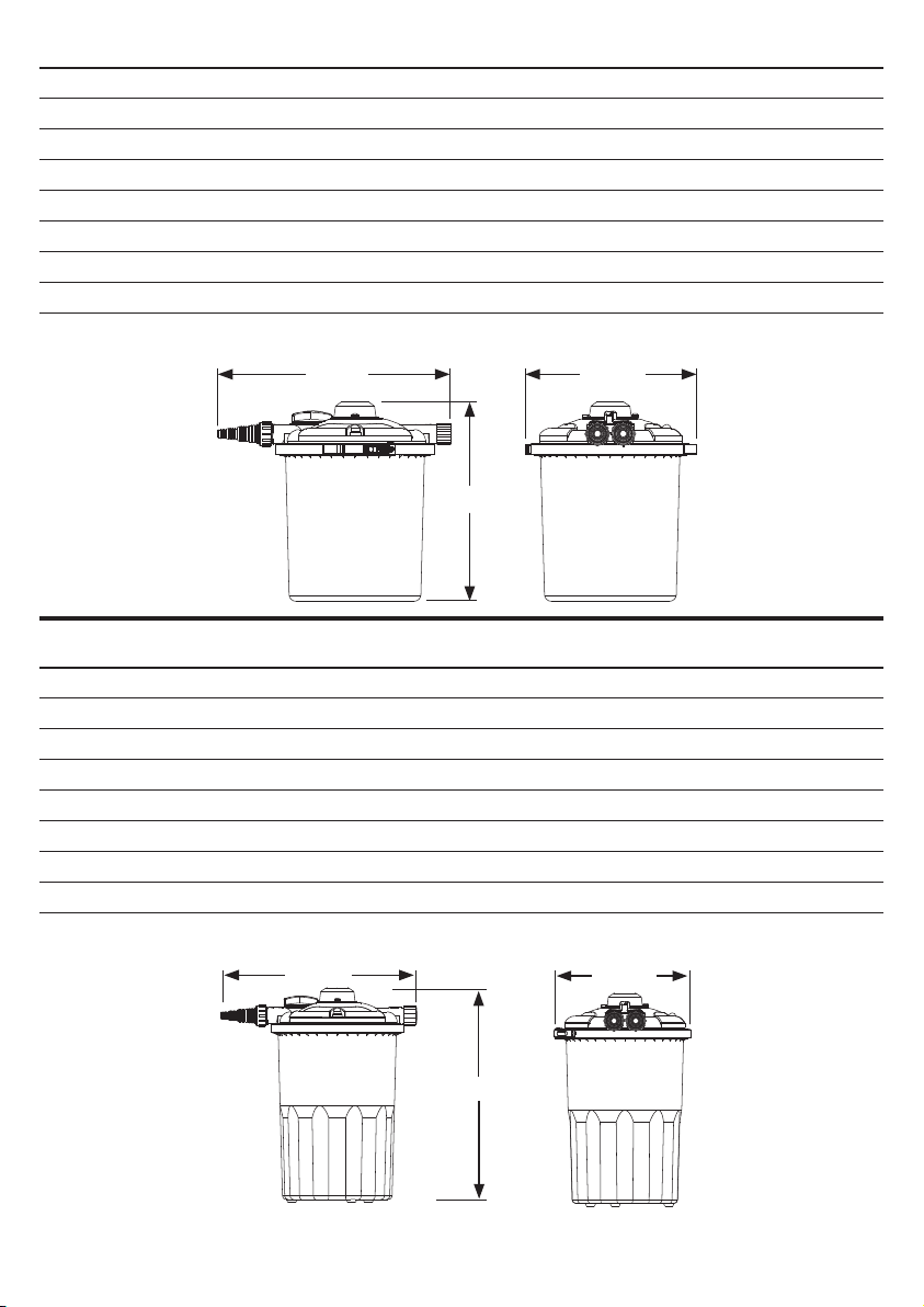
5. Dig a hole big enough for the lter to sit in and at a
depth where the retaining ring is left exposed out of
the ground to allow for easy maintenance.
6. Recess the lter into the previously dug hole and
carefully backll around the lter.
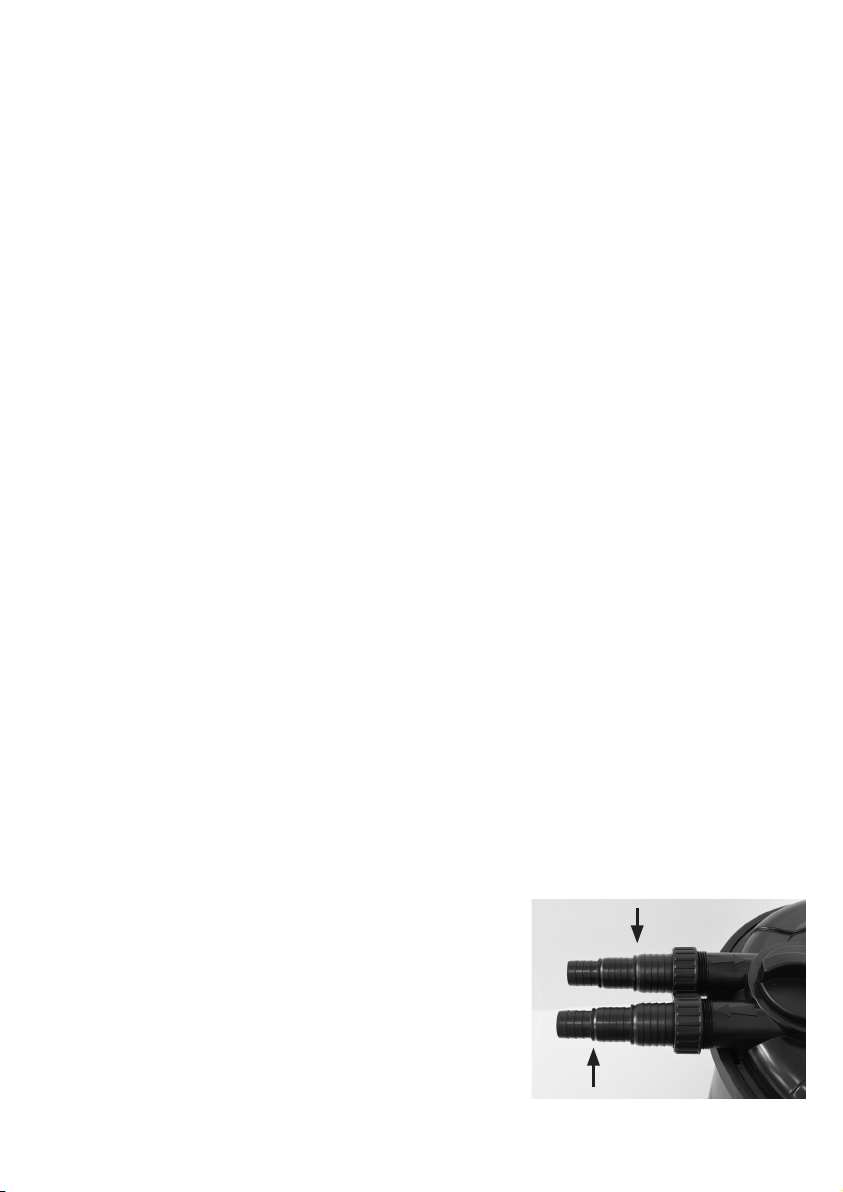
7. To maximize ow performance, use a hacksaw to
remove any smaller steps on the barb tting than
the tubing being used. If connecting to Sch. 40 PVC
exible pipe, use the included 1 1/2" adaptor tting
with a rubber coupler (sold separately) to connect
the lter and the pipe.
Step 7
Cut here for
1 1/2" tubing
Cut here for
1 1/4" tubing

3
8. Secure the prepared barb ttings to the lter inlet
(arrow pointing in) and outlet (arrow pointing out).
Be sure to use the gasket as shown and hand tighten
nut onto lter. Do not overtighten.
9. Connect the tubing from the pump to the barbed
tting or 1 1/2" PVC adaptor on the inlet of the lter
and secure with a clamp.
10. Connect the tubing for the waterfall to barbed tting
or 1 1/2" PVC adaptor tting on the outlet of the lter
and secure with a clamp.
11. Run the tubing to the waterfall and attach to a
waterfall device if applicable. Burying the tubing will
produce the most natural look for your pond.
12. If the pressure lter unit is equipped with a UV
light make sure it is properly plugged into a GFCI
protected outlet. DO NOT operate the UV light until
the pump is running.
13. For units with UV, there is a connection at the ballast
to be made. Connect the 2-pin ttings by aligning
the ends properly and rmly pushing them together.
Secure by hand tightening the nut to create a
weatherproof seal. This connection is not meant to
be submersed but is good for outdoor use.
14. Conrm the backwash valve is in the “
RUN
” position
and plug in the pump and UV. To switch on the UV
remove the clear top and once activated secure clear
top back on lter with thumbscrew. Observe the lter
and connections for any leaks.
15. Conceal your pressure lter and tubing with your
choice of landscaping. Fake rocks are a good option
to hide the lter.
Operation Tips
Running the ltration system continuously is the best way to keep your pond looking
its best. Once installed the lter will take a few weeks to build up sucient nitrifying
bacteria in the system.
To maximize the lter’s performance and avoid ineectiveness or damage to the lter,
be sure to match the ow rate with the lter’s specications.
These lters are not to be used in the winter during freezing conditions. Be sure to
disconnect and drain the lter to store in a warmer location for the winter.
Steps 8, 9, 10
Step 13
OUTLET
INLET
Step 14

4
Backwashing, Cleaning and Replacing the Filter Pads.
When installed on a dirty pond, the foam pads will need to be cleaned more frequently
until the pond clears. As pond conditions stabilize, the time between cleanings will
increase. Pads are meant to be slightly dirty, there is no need to overclean them. The
EC2600/2600U/3900/3900U units include a cleaning indicator that pops up when pads
require backwashing or cleaning. If you notice a decrease in water ow, the lter may
need to be cleaned. Using the Backwash feature will rinse the pads and extend time
between full cleanings. Also, be sure to check that the pump is not clogged. Replace the
pads when they show signs of wear to maximize ltration capabilities.
Backwashing the Filter
1. For units with UV, be sure to turn this o or unplug it
before servicing. Unplug the pump.
2.
Remove the cap from the backwash port labeled
“CLEAN”. Be sure to not lose the gasketed plug and nut.
3. Connect tubing to the backwash port with supplied
barb hose connector or PVC adaptor ttings. The hose
can run to a garden area as the backwash water from
the pond is good for watering.
4. Rotate the backwash valve to “CLEAN”.
5. Turn on the pump and water will begin to rinse the
pads and exit the backwash port.
6. Run the pump for a few minutes. The water from the
backwash should begin to clear. Shut the pump o.
Note -
If water does not clear, a full cleaning of the
pads may be required. Full cleanings also take less
pond water than extended backwashing. For example,
a pump that produces 2000 gallons per hour (33 gallons
per minute) would use 167 gallons of pond water in 5
minutes. This can be very eective when doing water
changes, but you do not want to pump too much water
out of your pond just to do a backwash cycle.
7. Once backwash is complete, remove the connector
and hose from backwash port and replace gasketed
plug and secure with nut.
8. Rotate the backwash valve back to “RUN” and turn
pump and UV (if applicable) back on.
9. Replace water in the pond lost to backwashing.
If necessary, be sure to properly treat the water with
dechlorinator to protect your sh.
10. Be sure to verify the system is functioning properly
and check for leaks.
Step 2
Step 4 - CLEAN Position
Step 8 - RUN Position

5
Full Pad Cleaning or Replacement
1. For units with UV, be sure to turn this o or unplug it
before servicing. Unplug the pump before opening.
2. Loosen the locking nuts that secure the tubing
connectors to the lter and remove them from the lid.
Be sure not to lose the gaskets that seal the connectors
to the lter.
3. To access the pads and bio-balls for cleaning or
replacement, the top of the lter can be removed by
taking o the clamp. Start by sliding the locking wedge
to release tension.
4. To remove the clamp completely depress the tab and
open the clamp wide enough to remove from the lter.
5. Carefully lift the lid o the tub. Be sure to not lose the
O-Ring that seals the lid and tub.
6. Filter pads can be removed and rinsed with clean water.
Replace with new pads if they are showing signs of wear.
EC2600/2600U units have two pads and the EC3900/
EC3900U units have three pads.
7. Bio-balls can be accessed by removing the plate at the
bottom. Bio-balls can be rinsed with pond water to get
larger debris from them, but do not overclean these.
This is where the benecial bacteria grow.
8. Replace items in reverse order and install the O-ring with
lid assembly back on lter body.
9. Secure the clamp around the lter by closing the clamp
rmly and sliding locking wedge into place for a tight seal.
10. Reattach hose connections with gaskets and locking
nuts securely in place.
11. Plug in pump and UV. Observe the lter and check for
leaks.
Step 3
Step 4
Step 6

6
UV Lamp and Quartz Sleeve Replacement
For units with UV lights it is recommended that a new lamp
be installed after 12 months of use. While the light might
still turn on, the eectiveness of the UV light diminishes
over time. Quartz sleeves are typically long lasting and only
require replacement if they break or develop a leak due to
the age of the seals.
UV Lamp Replacement
1. Unplug the UV unit and the pump.
2. Remove thumbscrew from clear lid on top of unit.
Remove the clear lid. TIP: Use it to hold the various
screws during the process.
3. Remove the two screws and the plastic cord retainer
clip.
4. Remove the three screws that hold the UV lamp
assembly in the unit. Take care not to lose any of the
screws during this process.
5. Remove the UV assembly from the unit.
6. Remove the old UV lamp.
7. Carefully remove the black stabilizing protector on the
end of the old lamp.
8. Do not touch the new lamp with your ngers. The
oil from your skin can cause pre-mature failure of
the lamp.
9. Hold the new UV lamp with a glove or clean cloth and
plug into the UV housing. Transfer the black stabilizing
protector unit to the new lamp.
10. Carefully slide the assembly with the new lamp back
into place and secure it with screws.
11. Reattach the cord retainer clip with the two screws.
12. Replace the clear top cover and secure with
thumbscrew.
13. Return the unit back to service.
Step 2
Step 3
Step 9
Step 4

7
UV Quartz Sleeve Replacement
1. Unplug the UV unit and the pump.
2. Remove thumbscrew from clear lid on top of unit.
Remove the clear lid. TIP: Use it to hold the various
screws during the process.
3.
Remove the two screws and the plastic cord retainer clip.
4. Remove the three screws that hold the UV lamp
assembly in the unit. Take care not to lose any of the
screws during this process.
5.
Remove the UV assembly from the unit and carefully set
it aside being careful not to touch the UV lamp. If you
are replacing the UV lamp, follow the instructions above.
6. Remove remaining three screws and the UV Sleeve
assembly from the unit
7. Be sure to use caution as the quartz sleeve is glass
and can break. If the sleeve is broken use proper
protection for your hands and eyes while cleaning
glass from the lter.
8. I
f you are cleaning the sleeve do so at this point. Be sure
to inspect the gasket is in good shape and skip to Step
10 to reinstall the sleeve once cleaned.
9. To replace the sleeve with a new one, you may need
to remove the interior cap by removing three screws
and transferring it to the new sleeve. The stem on this
section activates the micro switch on the UV starter.
10. Once the presence of the interior cap is veried on
the new sleeve assembly, install the new gasket and
sleeve assembly into lter unit. Be sure to align the
holes properly to receive the screws. Also, be sure
the sleeve is positioned correctly with the small arrow
pointing toward the front of the lter. Verify the stem
on the interior cap is in the correct position.
11. Secure the sleeve with three screws as shown.
13. Carefully replace the UV assembly into the lter. Be sure it is seated properly and secure
with three screws.
14. Reattach the cord retainer clip with the two screws.
15. Replace the clear top cover and secure with thumbscrew.
16. Return the unit back to service.
Steps 6, 11
Step 9
Step 4

8
Top Cover Thumb Screw
Switch
18 Watt UV Lamp
Stabilizer
Interior Cap
Sleeve Top Fitting
Sleeve Gasket
Cleaning Indicator
Backwash Dial
Quartz Sleeve
Micro Switch
Power
Cord
Nut
Filter Lid
Plug
Gasket
Cord Retainer
Clip
Bio-Balls
Bottom Plate
O-Ring
Clamp
Part # Description
EC26UB 18 Watt UV Replacement Lamp
EC26US Replacement Quartz Sleeve Assembly
EC2639BK Barb Hose Connector Set
(Includes 3 Connectors, 3 Nuts, 3 Gaskets)
EC26F Replacement Filter Pads (Includes 1 Coarse, 1 Fine)
EC2639L O-Ring - Seals Lid and Tub
EC2639C Clamp - Secures Lid
EC2600U Exploded View
Replacement Parts
Coarse Pad
Fine Pad
Backwash
Valve
Barb Hose
Connector
Image for reference only

9
Part # Description
EC39UB 24 Watt UV Replacement Lamp
EC39US Replacement Quartz Sleeve Assembly
EC2639BK Barb Hose Connector Set
(Includes 3 Connectors, 3 Nuts, 3 Gaskets)
EC39F Replacement Filter Pads (Includes 1 Coarse, 1 Medium, 1 Fine)
EC2639L O-Ring - Seals Lid and Tub
EC2639C Clamp - Secures Lid
EC3900U Exploded View
Replacement Parts
Top Cover Thumb Screw
Switch
24 Watt UV Lamp
Stabilizer
Interior Cap
Sleeve Top Fitting
Sleeve Gasket
Cleaning Indicator
Backwash Dial
Quartz Sleeve
Micro Switch
Power
Cord
Nut
Filter Lid
Plug
Gasket
Cord Retainer
Clip
Bio-Balls
Bottom Plate
O-Ring
Clamp
Coarse Pad
Medium Pad
Backwash
Valve
Barb Hose
Connector
Fine Pad
Image for reference only

10
Filter Specications
EC2600 EC2600U
Maximum Pond Size with Fish* (gallons) 1300 1300
Maximum Pond Size without Fish* (gallons) 2600 2600
UV/Watts n/a 18 Watts
Inlet/Outlet Sizes - Hose Barb 1", 1
1
/
4
", 1
1
/
2
" 1", 1
1
/
4
", 1
1
/
2
"
Inlet/Outlet Size - PVC Adaptor 1
1
/
2
" 1
1
/
2
"
Recommended maximum GPH 2600 2600
Volts / Frequency n/a 115 V / 60 Hz
Cord Length n/a 16 feet
*Fish load, amount of sunlight, etc. all aect actual maximum gallons ltered.
Filter Specications
EC3900 EC3900U
Maximum Pond Size with Fish* (gallons) 1950 1950
Maximum Pond Size without Fish* (gallons) 3900 3900
UV/Watts n/a 24 Watts
Inlet/Outlet Sizes - Hose Barb 1", 1
1
/
4
", 1
1
/
2
" 1", 1
1
/
4
", 1
1
/
2
"
Inlet/Outlet Size - PVC Adaptor 1
1
/
2
" 1
1
/
2
"
Recommended maximum GPH 3900 3900
Volts / Frequency n/a 115 V / 60 Hz
Cord Length n/a 16 feet
*Fish load, amount of sunlight, etc. all aect actual maximum gallons ltered.
21.26"
22.68"
14.92"
18.43"
21.26" 14.92"

11
Troubleshooting
If there is no water through the lter to the pond…
• Check if the pump is on and working.
• Check if the pump is clogged and clear debris if needed.
• Check if the plumbing lines to and from the lter are blocked or loose/leaking.
• Check that the backwash valve is in the “RUN” position.
If there is reduced ow through the lter...
• Check if pump is clogged and clear debris if needed.
• Check that the backwash valve is in the “RUN” position.
• Check if lter pads are clogged and clean/replace if needed.
• Check if the plumbing lines to and from the lter are blocked or loose/leaking.
If the water is not clear…
• The lter may be new and requires a few weeks to “mature” with nitrifying bacteria.
• The lter may be the wrong size for the pond.
• The
pump may be the wrong size for the pond and lter. See specication chart or box for details.
• The UV lamp may be burned out or old. Replace if broken or after 12 months of use.
• The foam pads may need to be backwashed or fully cleaned.
• The sh load and/or feeding rates may be too high.
If the lter is leaking…
• Check
that the gaskets and O-rings are seated properly and in good repair. Replace if needed.
• Check that the pump is properly sized for the lter.
• Check that the lter itself is not damaged or broken.

EasyPro Pond Products Limited Warranty
EasyPro Pond Products (“EasyPro”) warrants to the purchaser that this product ("Product") will be free
from any mechanical or material defects for a period of three years from the date of purchase. UV bulbs,
quartz sleeves, lter pads and O-rings are considered wearable items and are not covered under this
limited warranty
This warranty only covers properly installed and maintained Products sold by authorized EasyPro
Sellers who are subject to and follow EasyPro’s quality control standards. Please note that because
EasyPro is unable to control the quality of Products sold by unauthorized sellers, unless otherwise
prohibited by law, this warranty does not cover Products purchased from unauthorized sellers.
This warranty does not cover normal wear and tear, nor any deterioration suered through overloading,
improper use, negligence, improper installation, acts of God or accident. Similarly, any modication
made by the purchaser to the Product will cause the warranty to be null and void. This warranty does
not cover any cost associated with the installation or removal of the Product subject to a warranty
claim.
All returned items will be inspected to determine cause of failure before a warranty claim is approved.
The exclusive remedies provided hereunder shall, upon EasyPro’s inspection and option, be either
repair or replacement of the Product or parts covered under this warranty.
Making a Claim:
A Return Authorization (“RA”) number must rst be obtained by calling EasyPro at
800-448-3873 or via email at [email protected]. It is the purchaser’s responsibility to pay the return
shipping charges. Be sure to include the RA number, original receipt (in the form of an invoice or sales
receipt), your name, your return address and your phone number inside of the package. No warranty
claims will be honored without the original receipt that shows that your purchase was made from an
Authorized EasyPro Seller. Ensure the product is properly packaged and insured for the replacement
value. Damage due to improper packaging is the responsibility of the sender.
ALL OTHER EXPRESS OR IMPLIED WARRANTIES INCLUDING MERCHANTABILITY OF FITNESS
FOR A PARTICULAR PURPOSE ARE HEREBY LIMITED IN DURATION TO THE DURATION OF THE
WARRANTY AS DESCRIBED ABOVE. Some States do not allow limitations on how long an implied
warranty lasts, so the above limitations may not apply to you.
EasyPro shall not be held liable for any damages caused by defective components or materials of this
Product; or for loss incurred because of the interruption of service; or any consequential/incidental
damages and expenses arising from the production, sale, use or misuse of this Product. Some States
do not allow the exclusion or limitation of incidental or consequential damages, so the above limitation
or exclusion may not apply to you.
EasyPro shall not be held liable for any loss of sh, plants or any other livestock as a result of any
failure or defect of this Product. This warranty gives you specic legal rights, and you may also have
other rights that vary from State to State.
800-448-3873 • Grant, Michigan
www.easypro.com • [email protected]
6770 • 10/20
A4
This manual suits for next models
3
Table of contents
Other EasyPro Water Filtration System manuals
Popular Water Filtration System manuals by other brands

HTW
HTW HTW-FST3-O-160A9 manual

Pentair
Pentair FRESHPOINT GRO-475BP Installation and operation manual

Fluval
Fluval U4 instruction manual

Aries FilterWorks
Aries FilterWorks UNIX-00 installation instructions

Clean Water Systems
Clean Water Systems Pro-OX 8500 Installation and startup guide

amiad
amiad AMF-370K-S Installation and operation instructions