Eaton Green Motion User manual
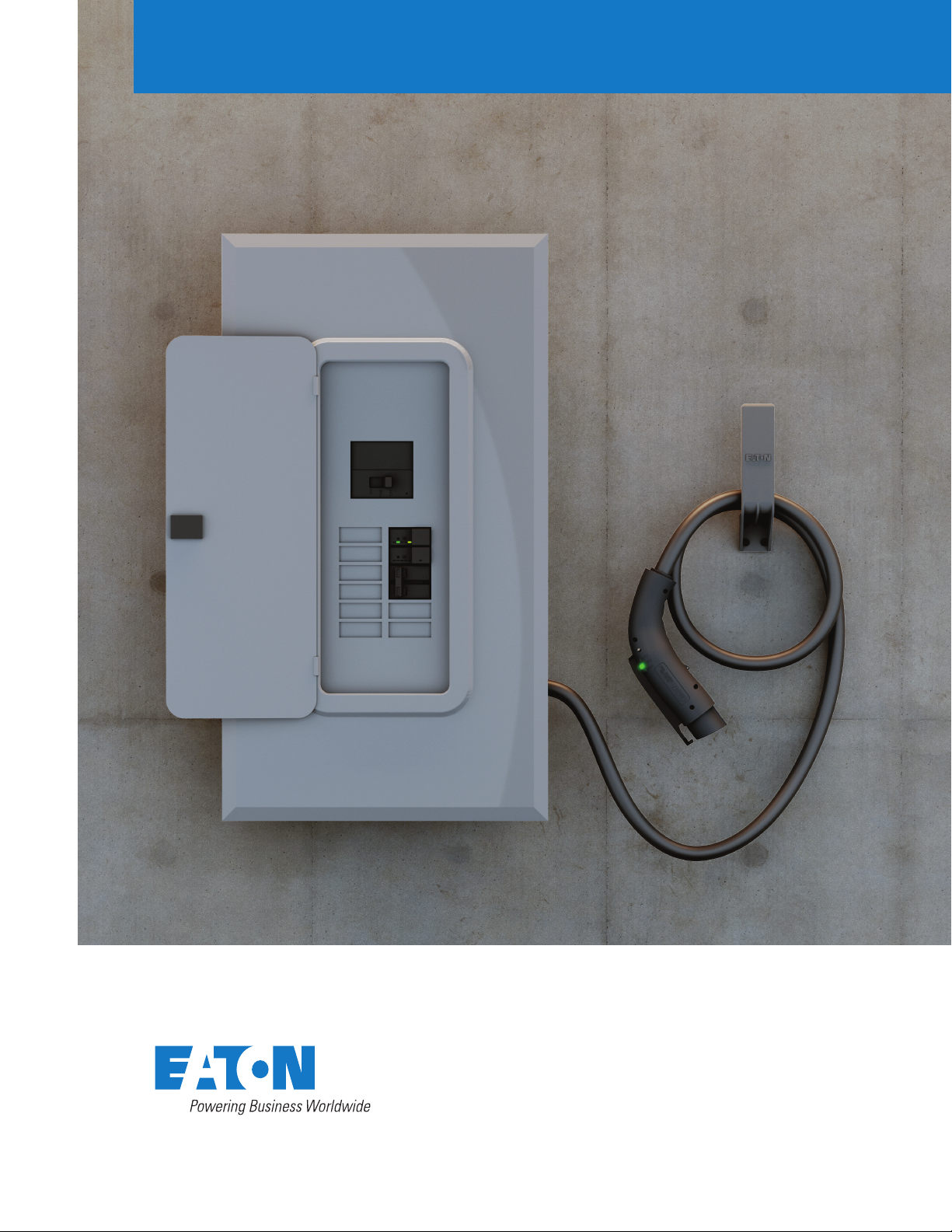
Installation guide:
EV direct connect and
junction box kits
Green Motion
EV smart breaker chargers
Fault
Ready
Active
EVCC-LED
240VAC 30A
Fault
Ready
Active
EVCC-LED
240VAC 30A

1
Installation Guide: EV direct connect and junction box kits
EV DIRECT CONNECT AND JUNCTION BOX KITS www.eaton.com
Contents
PRODUCT INTRODUCTION ........................................................................2–3
EV direct connect kit. ............................................................................2
EV direct connect + junction box kit. ................................................................2
EV smart breaker charger .........................................................................3
PACKAGE CONTENTS...............................................................................4
EV direct connect kit . ............................................................................4
EV direct connect + junction box kit . ................................................................4
ROUTINE OPERATION ............................................................................5–6
EV smart breaker charger operation . ................................................................5
LED indicator descriptions. ........................................................................6
INSTALLATION ..................................................................................7–15
Safety information . ..............................................................................7
General reference ...............................................................................8
EV direct connect and junction box kits installation ..................................................9–15
•Installation overview .........................................................................9
•A - Connect EV smart breaker charger...........................................................10
•B - Insert conductors into loadcenter............................................................11
•C - Connect EV connector ....................................................................12
•D - Connect EV smart breaker charger & EV connector ..........................................13–14
•E - Install the cord management bracket .........................................................15
FCC...............................................................................................16
CONNECT TO WI-FI ................................................................................17
TECHNICAL SPECIFICATIONS.......................................................................18
TROUBLESHOOTING...............................................................................19
2
Green Motion EV smart breaker chargers
EV DIRECT CONNECT AND JUNCTION BOX KITS www.eaton.com
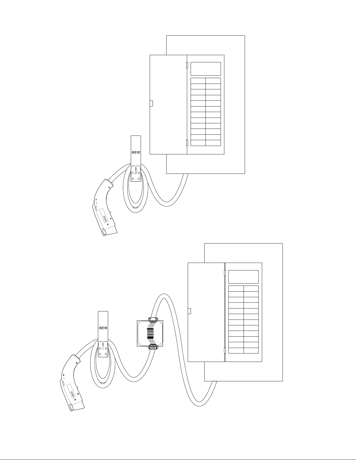
EV direct connect kit
EV direct connect + junction box kit
Installs directly in BR loadcenters or PRL3X panelboards close to where the electric vehicle is parked.
Installs directly in BR loadcenters or PRL3X panelboards. Includes a junction box for when the electric vehicle is
parked further away.

3
Installation Guide: EV direct connect and junction box kits
EV DIRECT CONNECT AND JUNCTION BOX KITS www.eaton.com
EV smart breaker charger
The EV smart breaker charger is
intended for charging plug-in hybrid
and all-electric vehicles and is compat-
ible with the Society of Automotive
Engineers J1772 charging standard.
In addition to traditional thermal-
magnetic protection, EV smart breaker
chargers:
• Protect from ground faults and
provide automatic reset so no user
interaction is needed.
• Instruct the vehicle on how much
current to draw to keep from
overloading the circuit.
• Protect users with interlocked power
so that power is never available at the
connector unless it is plugged into
an electric vehicle.

4
Green Motion EV smart breaker chargers
EV DIRECT CONNECT AND JUNCTION BOX KITS www.eaton.com
Package contents
EV direct connect kit (GMEV32BR-DC, GMEV32BAB-DC)
EV direct connect + junction box kit (GMEV32BR-JB, GMEV32BAB-JB)
1. 7.7 kW EV smart breaker charger
2. Cord management bracket
3. J1772 EV connector and 25 ft cordset
4. NM/SE connector
5. Junction box
Fault
Ready
Active
US TYPE 3R IP54
SAE J1772
TM
1
2
3
4
Fault
Ready
Active
US TYPE 3R IP54
SAE J1772
TM
15
2
3
x2
4
Required items not included:
• #10 woodscrew 1-1/2 inches long - x4
1. 7.7 kW EV smart breaker charger
2. Cord management bracket
3. J1772 EV connector and 25 ft cordset
4. NM/SE connector

5
Installation Guide: EV direct connect and junction box kits
EV DIRECT CONNECT AND JUNCTION BOX KITS www.eaton.com
EV smart breaker charger operation
QUICKLAG thermal-magnetic breaker
The EV smart breaker charger contains integral solenoid controlled contacts in series with QUICKLAG™
thermal-magnetic breaker.The instructions below describe how to operate the main handle of the EV smart
breaker charger:
• Main handle must be in the ON position to supply power to theload
• When breaker trips, handle will move to the center-trippedposition
• To reset breaker, push handle to OFF position, and then to ONposition
GFCI test button Initiates a ground fault self-test. Recommended to perform this test when J1772 connector is plugged into the EV.
EV charger reset button Resets the EV charger.
EV charger status LEDs Display status of the EV charger and various fault conditions, if present.
Smart breaker display button When pressed momentarily, Wi-Fi signal strength is displayed on smart breaker status LEDs. For non-OCPP EV chargers, pushing
this button two times will initiate a manual override of any schedules and will allow for a single charge session. If the LED is
flashing red, double press and hold this button for 15 seconds to clear the fault.
Smart breaker reset button Reset the Wi-Fi antenna module and regain connectivity or clear any errors that may have occurred during the BlinkUp process.
Smart breaker status LEDs LEDs show how loaded the circuit is compared to its capacity. The color of the LEDs will range from off indicating no load or too small of
a load detected. Green indicates a low load, yellow indicates a medium load, and red indicates a high load. If the LEDs are flashing, this
indicates that the current exceeds the rating of the smart breaker. When the smart breaker display button is pressed, these LEDs also
show the Wi-Fi signal strength.
BlinkUp status LED Indicates the status during the BlinkUp process.
Thermal-magnetic breaker handle To manually trip or reset the thermal-magnetic breaker.
Remote contact indicator Indicates status of secondary contacts (Open: Green / Close: Red ).
Item Description
GFCI test button
EV charger reset button
EV charger heartbeat LED
BlinkUp receiver/network status amber LED
EV charger
status LEDs
Smart breaker
reset button
Smart breaker
display button
Electronic line
connection
Terminals
(for connection to
loadcenter bus)
Smart breaker
status LEDs
Thermal-magnetic
breaker handle Remote contacts indicator
Thermal-magnetic pole 1
Thermal-magnetic pole 2
Terminals 1 and 2
(for connection
to eld wiring)
Neutral pigtail
(for electronics
module power)
Terminal 4 (for connection to J1772 pilot)
Terminal 3 (for connection to +12 Vdc)
Ground pigtail
Terminal 5
(for connection to ground)

6
Green Motion EV smart breaker chargers
EV DIRECT CONNECT AND JUNCTION BOX KITS www.eaton.com
LED indicator descriptions
1. Not a valid J1772 State, the EV smart breaker charger will commence charging when prompted to through the EV smart breaker charger
application.
2. J1772 State D, the ventilation required state, is not supported and will cause the EV smart breaker charger to enter the fault state.
3. Cold LoadTimeout: Following a complete loss of power during an active charging session, a phenomenon occurs called Cold LoadTimeout.
When power is restored, there may be a 2–5 minute delay to resume charging per SAE J2894.
State Blink Type Color
Idle / Ready No Blink
EV connectorEV pole only
HeartbeatEV charger heartbeat
No Blink
Medium
Long
Short
Vehicle connected
Vehicle connected, EVSE ready
Vehicle charging state, EVSE not ready (1)
Charging
Medium
Long
Loss of line power
Fault (2)
Long
No Blink
Medium
Vehicle connected
J1772 State D (2)
Cold Load Timeout Active (3)
EV connector EV smart breaker charger
EV pole
7
Installation Guide: EV direct connect and junction box kits
EV DIRECT CONNECT AND JUNCTION BOX KITS www.eaton.com
Installation
Important safety instructions
DANGER
FAILURE TO FOLLOW THESE INSTRUCTIONS COULD RESULT IN
DEATH, PERSONAL INJURY, OR PROPERTY DAMAGE. CIRCUIT
BREAKERS MUST BE INSTALLED AND SERVICED BY A QUALIFIED
ELECTRICIAN. REMOVE ALL POWER SOURCES TO THE PANEL
BEFORE STARTING INSTALLATION OR MAINTENANCE.
WARNING
THIS EQUIPMENT SHOULD BE INSTALLED, ADJUSTED, AND
SERVICED BY QUALIFIED ELECTRICAL PERSONNEL FAMILIAR
WITH THE CONSTRUCTION AND OPERATION OF THIS TYPE OF
EQUIPMENT AND THE HAZARDS INVOLVED. FAILURE TO OBSERVE
THIS PRECAUTION COULD RESULT IN DEATH OR SEVERE INJURY.
READ THIS MANUAL THOROUGHLY AND MAKE SURE YOU
UNDERSTAND THE PROCEDURES BEFORE YOU ATTEMPT TO
OPERATE THIS EQUIPMENT. THE PURPOSE OF THIS MANUAL IS
TO PROVIDE YOU WITH INFORMATION NECESSARY TO SAFELY
OPERATE, MAINTAIN, ANDTROUBLESHOOT THIS EQUIPMENT.
KEEP THIS MANUAL FOR FUTURE REFERENCE.
DO NOT USE THIS PRODUCT IF THE EV CONNECTOR CORD IS
FRAYED, HAS DAMAGED INSULATION, OR HAS ANY OTHER
INDICATION OFDAMAGE.
DO NOT USE THIS PRODUCT IF THE EV SMART BREAKER CHARGER,
THE EV CONNECTOR, OR THE LOADCENTER IS BROKEN, CRACKED,
OPEN, OR SHOWS ANY OTHER INDICATION OF DAMAGE.
INTENDED FOR USE WITH PLUG-IN ELECTRIC VEHICLES ONLY.
PREMISE VENTILATION NOT REQUIRED.
THIS DEVICE SHOULD BE SUPERVISED WHEN USED AROUND
CHILDREN.
WARNING
TURN OFF OR DISCONNECT THE POWER SUPPLYING THIS
EQUIPMENT BEFORE BEGINNING WORK. THIS MAY REQUIRE THAT
YOU CONTACT YOUR ELECTRIC UTILITY TO DISCONNECT POWER TO
AN EXISTING LOADCENTER. THE LINE SIDE OF THE MAIN BREAKER
IS ENERGIZED UNLESS POWER IS DISCONNECTED UPSTREAM.
EATON WILL NOT ASSUME RESPONSIBILITY FOR PROPERTY
DAMAGE OR PERSONAL INJURY RESULTING FROM MISUSE OF THE
INFORMATION IN THIS PUBLICATION.
NOTICE
INSTALL EQUIPMENT IN CONFORMANCE WITH CODES.
Grounding instructions
WARNING
IMPROPER CONNECTION OF THE EQUIPMENT-GROUNDING
CONDUCTOR IS ABLE TO RESULT IN A RISK OF ELECTRIC SHOCK.
CHECK WITH A QUALIFIED ELECTRICIAN OR SERVICEMAN IF YOU
ARE IN DOUBT AS TO WHETHER THE PRODUCT IS PROPERLY
GROUNDED.
For a permanently connected product
This product must be connected to a grounded, metal,
permanent wiring system, or an equipment-grounding
conductor must be run with the circuit conductors and
connected to the equipment grounding terminal or lead on
the product.
REFERENCE THE QR CODE ON THE EV SMART BREAKER
CHARGER FOR LATEST DOCUMENTATION AS THE
INFORMATION CONTAINED IN THIS MANUAL IS SUBJECT
TO CHANGE.
This product must be installed in accordance with the
National Electrical Code®(NEC®) and any applicable local
codes. Before installing equipment, check with your local
electrical inspector for requirements and information. If you
have questions or need assistance, contact a qualified elec-
trical contractor.
SAVE THESE INSTRUCTIONS.

8
Green Motion EV smart breaker chargers
EV DIRECT CONNECT AND JUNCTION BOX KITS www.eaton.com
Definitions
EVSE—Electric Vehicle Supply Equipment. EVSE is a
general term used for all of the equipment used to supply
electricity to the car.
J1772—SAE Recommended Practice for conductive charg-
ing of hybrid and electric vehicles. This standard spells out
the physical dimensions of the J1772 connector and the
pilot communication between the plug-in vehicle and the
EVSE.
Pilot—The communication signal through the J1772
connector. This signal tells both the vehicle and the EVSE
when both are ready to charge and how much current is
permitted in the circuit. This signal is part of the SAE J1772
standard.
SAE—Society of Automotive Engineers. The group that
organizes and leads committees of transportation experts
to create standards, such as J1772, for the transportation
industry.
ADA—Americans with Disabilities Act.
UL®—Underwriters Laboratories. UL is an accredited stan-
dards developer in the U.S. and Canada.
Moving, transporting, and storage instructions
Store the equipment indoors and in its original packaging
until it isready to be installed. Storage temperature should
be between –40°C and +60 °C. Never attempt to lift, move,
or carry the equipment by the EV connector cord or power
cord. Improper storage or handling may cause damage to the
equipment.
WARNING
ONLY QUALIFIED PERSONNEL FAMILIAR WITH THE OPERATION
AND CONSTRUCTION OF THIS EQUIPMENT SHOULD INSTALL,
ADJUST, MODIFY, AND SERVICE THIS EQUIPMENT. FAILURE TO
FOLLOW THE INSTRUCTIONS COULD RESULT IN SEVERE BODILY
INJURY OR DEATH.
NOTICE
THE USER IS RESPONSIBLE FOR CONFORMING TO ALL LOCAL AND
NATIONAL ELECTRICAL CODES AND STANDARDS APPLICABLE IN
THE JURISDICTION IN WHICH THIS EQUIPMENT IS INSTALLED.
NEC Article 625 requires that the coupling means of the
electric vehicle supply equipment shall be stored or located
at a height of not less than 18 inches (450 mm) and not
more than 4 ft (1.2 m) above the floor level for indoor loca-
tions and 24 inches (600 mm) above the grade level for
outdoor locations.
Americans with Disabilities Act requirements to
consider for workplace charging installation
The ADA and workplace charging
The Americans with Disabilities Act (ADA) is a federal civil
rights law that prohibits discrimination in public places
against individuals with disabilities. As an employer installing
plug-in electric vehicle (PEV) charging stations, also known
as electric vehicle supply equipment (EVSE), you need to
follow special design guidelines to accommodate people
with disabilities, as required by the ADA. Although the ADA
does not provide design standards for charging station-
equipped parking spots, several industry studies and PEV
planning guides do. In addition, several plans developed
under the U.S. Department of Energy’s (DOE) Clean Cities
EV Community Readiness projects describe best practices
for installing ADA-compliant charging stations.
Best practices for designing ADA-compliant
PEV charging stations
When designing ADA-compliant PEV charging stations,
consider accessibility, ease of use, and safety for disabled
drivers, including those using wheelchairs or other assistive
equipment. Key considerations include ensuring adequate
space for exiting and entering the vehicle, unobstructed
access to the EVSE, free movement around the EVSE and
connection point on the vehicle,
as well as clear paths and close proximity to any building
entrances.
For information about the ADA, including the revised
2010 ADA regulations, please visit the Department’s
website: http://www.ada.gov; or, for answers to specific
questions, callthe toll-free ADA information line at 800-514-
0301 (voice) or 800-514-0383 (TTY).
48” max
15” min
10” max
48” max
34” max
10” max
48” max
15” min
48” max
15” min
10” max
48” max
34” max
10” max
48” max
15” min
48” max
15” min
10” max
48” max
34” max
10” max
48” max
15” min

9
Installation Guide: EV direct connect and junction box kits
EV DIRECT CONNECT AND JUNCTION BOX KITS www.eaton.com
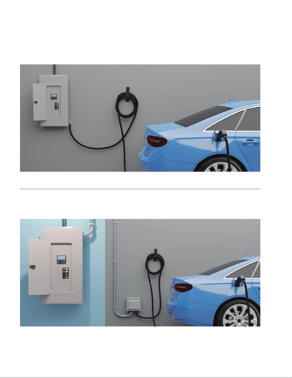
EV direct connect + junction box kit installation in an Eaton BR loadcenter or PRL3X panelboard
The following sections detail the instructions for various installation options.
Failure to follow these instructions may result in nonfunctional and/or unprotected equipment.
Fault
Ready
Active
EVCC-LED
240VAC 30A
Fault
Ready
Active
EVCC-LED
240VAC 30A
EV direct connect kit installation in an Eaton BR loadcenter or PRL3X panelboard
10
Green Motion EV smart breaker chargers
EV DIRECT CONNECT AND JUNCTION BOX KITS www.eaton.com
EV DIRECT CONNECT AND JUNCTION BOX KITS INSTALLATION
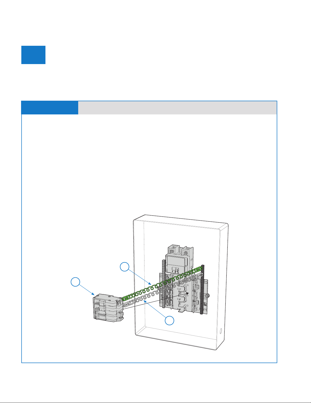
Connect EV smart breaker charger
A
• Disconnect power to the loadcenter or panelboard where the EV smart breaker charger is being
installed.
• Remove the loadcenter or panelboard deadfront.
• Ensure the EV smart breaker charger handle is in the OFF position.
• Connect the coiled, white “pigtail” conductor (1) from the circuit breaker to the neutral bus terminal
(ensure the connection is secure per the designated torque specifications).
• Connect the green “pigtail” conductor (2) to panel ground (ensure the connection is secure per
the designated torque specifications).
• Install the EV smart breaker charger (3) to the desired location in the loadcenter/panelboard.
• If the EV smart breaker charger is a type BAB bolt-on device, screw the breaker into the panelboard
“LINE” bus.
• If the EV smart breaker charger is a type BR plug-on device, plug the breaker into the loadcenter
“LINE” bus.
STEP A-1 EV direct connect and junction box kits
Follow the steps below, in addition with the considerations listed on page 9, in order to ensure proper
installation and wiring of the EV smart breaker charger and the EV connector and cordset.
1
2
3
Reference:
1. Neutral - White pigtail conductor
2. Ground - Green pigtail conductor
3. EV smart breaker charger
Figure 1
11
Installation Guide: EV direct connect and junction box kits
EV DIRECT CONNECT AND JUNCTION BOX KITS www.eaton.com
EV DIRECT CONNECT AND JUNCTION BOX KITS INSTALLATION
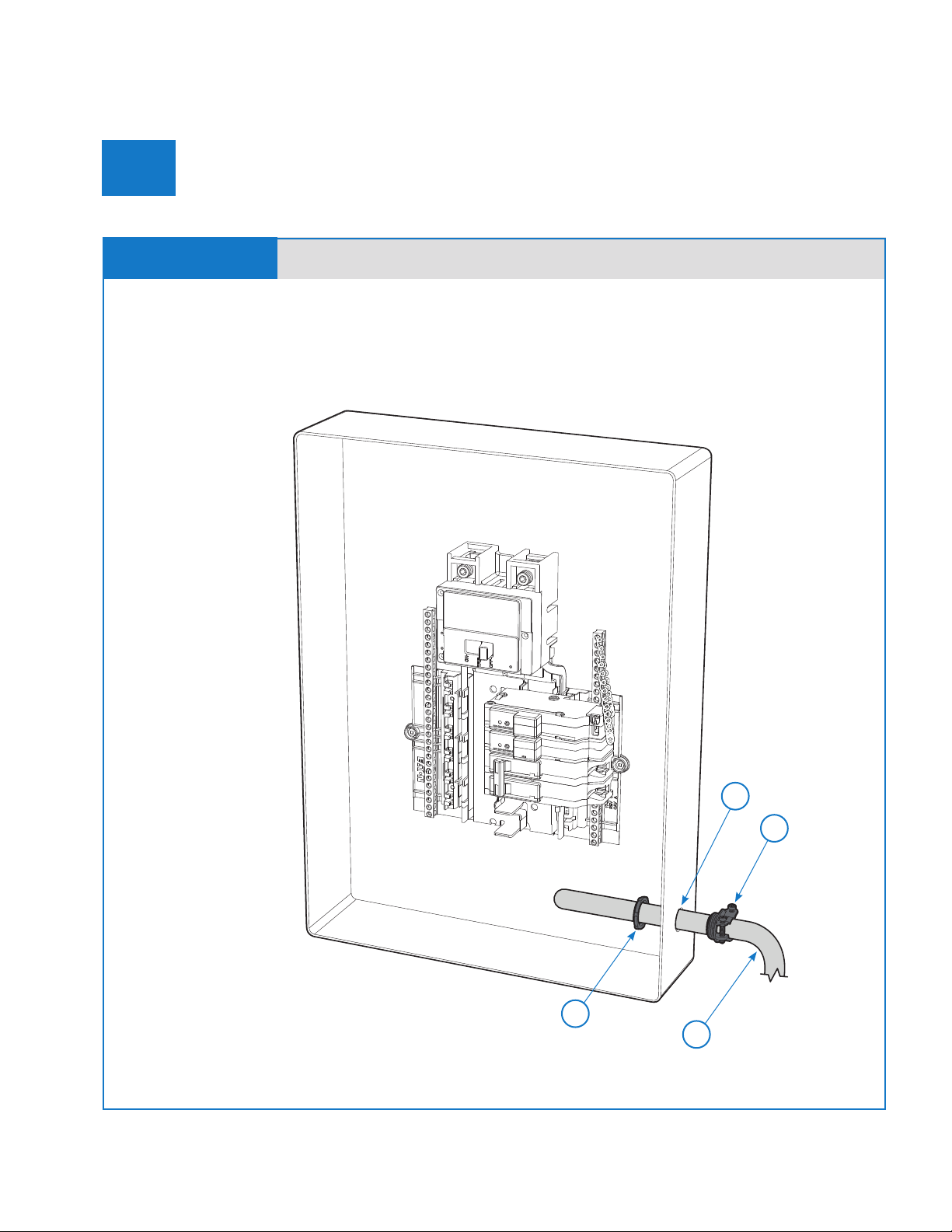
Insert conductors into loadcenter
B
• Conductors from the EV connector or junction box are connected to the EV smart breaker charger
directly inside the loadcenter. The NM/SE connector (1) for the EV connector cord or junction box
conductors (2) must be installed at the loadcenter knockout (3).
STEP B-1
4
2
1
EV direct connect and junction box kits
3
Reference:
1. 3/4 inch NM/SE connector
2. EV connector cord or junction box conductors
3. Loadcenter knockout
4. NM/SE connector locknut
Figure 2

12
Green Motion EV smart breaker chargers
EV DIRECT CONNECT AND JUNCTION BOX KITS www.eaton.com
EV DIRECT CONNECT AND JUNCTION BOX KITS INSTALLATION
Connect EV connector
C
• Connect the EV smart breaker charger and the EV connector and cordset.
• After the EV smart breaker charger is installed, attach the loadcenter or the panelboard deadfront.
• Energize the loadcenter or the panelboard. The EV smart breaker charger electronics should power
immediately, and the BlinkUp™ status LED will begin blinking. The indicator LEDs on the EV
connector will begin blinking. If no LED indicators are on, there is no power to the EV connector.
• Finally, ensure the EV smart breaker charger handle is in the ON position. Turn the EV smart breaker
charger on by moving the breaker handle from the OFF to the ON position.
STEP C-1 EV direct connect kit
EV connector wire color code:
1. (GREEN) EV connector ground
2. (BLUE) +12 Vdc
3. (ORANGE) J1772 pilot
4. (BLACK) Line 2
5. (RED) Line 1
Figure 3
NOTE:The pilot conductor (ORANGE) is 1 inch shorter than
all other conductors in the EV connector cord assembly. This
difference in conductor lengths must be maintained to comply
with NFPA Article 625.19.
2
3
5
4
1

13
Installation Guide: EV direct connect and junction box kits
EV DIRECT CONNECT AND JUNCTION BOX KITS www.eaton.com
EV DIRECT CONNECT AND JUNCTION BOX KITS INSTALLATION
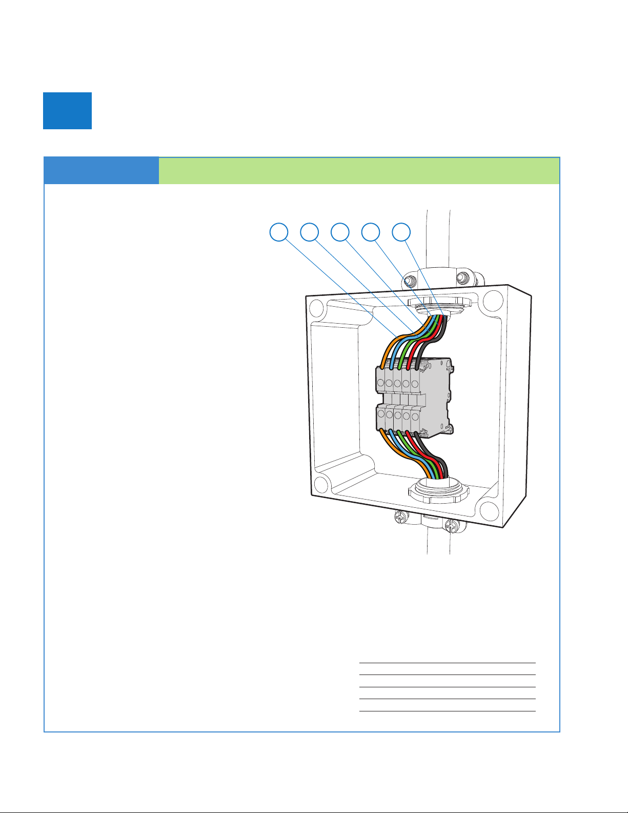
Connect EV smart breaker charger & EV connector
D
Conductors from the EV connector
are connected to the EV smart breaker
charger inside the approved junction
box via terminal blocks as described in
the following steps.
• Open the junction box cover and mount
the junction box to the wall.
• Remove the appropriate ¾-inch junction
box knockouts (1) to insert the EV smart
breaker charger conductors (2) and EV
connector cord (3).
• Install the NM/SE connector (4) in the
knockout where the EV connector cord
will be inserted.
• Insert the EV connector cord through
the NM/SE connector in the knockout.
STEP D-1 EV direct connect + junction box kit
1
1
2
3
4
Supply line conductors
enclosed in conduit
per NEC and local
codes. All conductors
rated at highest
conductor rating.
Reference:
1. NM/SE connector knockout
2. EV smart breaker charger conductors
3. EV connector cord
4. NM/SE connector
Figure 4
14
Green Motion EV smart breaker chargers
EV DIRECT CONNECT AND JUNCTION BOX KITS www.eaton.com
EV DIRECT CONNECT AND JUNCTION BOX KITS INSTALLATION
Connect EV smart breaker charger & EV connector
D
STEP D-2 EV direct connect + junction box kit
Connection data:
Connection method Screw connection
Screw thread M4
Stripping length 39.00 inches (10.0 mm)
Tightening torque, minimum 13.30 in-lb (1.5 Nm)
Tightening torque, maximum 15.90 in-lb (1.8 Nm)
• Terminate all conductors of the
EV connector to the terminal blocks.
Match the color of each EV connector
conductor to the color of the terminal block.
• Tighten the NM/SE connector.
• Remove the appropriate ¾-inch loadcenter
knockouts.
• Secure the EV smart breaker charger
conductors to the junction box and loadcenter.
• High-voltage conductors (Line 1, Line 2, EV
connector ground) and low-voltage conductors
(+12 Vdc and J1772 Pilot) can be routed within
the same conduit if all insulated conductors
are rated for at least 250 V. Otherwise, the
high-voltage and low-voltage conductors must
occupy different conduit.
• Secure the conductors to the junction box and
loadcenter using two NM/SE connectors.
• Connect the conductors in the terminal blocks
according to the wiring diagram to the right.
• Tighten all connectors.
• Install the cord management bracket on the
wall near the junction box. (Instructions for
installing the cord management bracket can
be found in Step E-1). The cord management
bracket must be installed in an orientation so
that the EV connector cable coming out of the
junction box can be wrapped around the cord
management bracket.
NOTE:The pilot conductor (ORANGE) is 1 inch shorter than
all other conductors in the EV connector cord assembly. This
difference in conductor lengths must be maintained to comply
with NFPA Article 625.19.
EV connector wire color code:
1. (ORANGE) J1772 pilot
2. (BLUE) +12 Vdc
3. (GREEN) EV connector ground
4. (RED) Line 1
5. (BLACK) Line 2
Figure 5
4 531 2
15
Installation Guide: EV direct connect and junction box kits
EV DIRECT CONNECT AND JUNCTION BOX KITS www.eaton.com
EV DIRECT CONNECT AND JUNCTION BOX KITS INSTALLATION
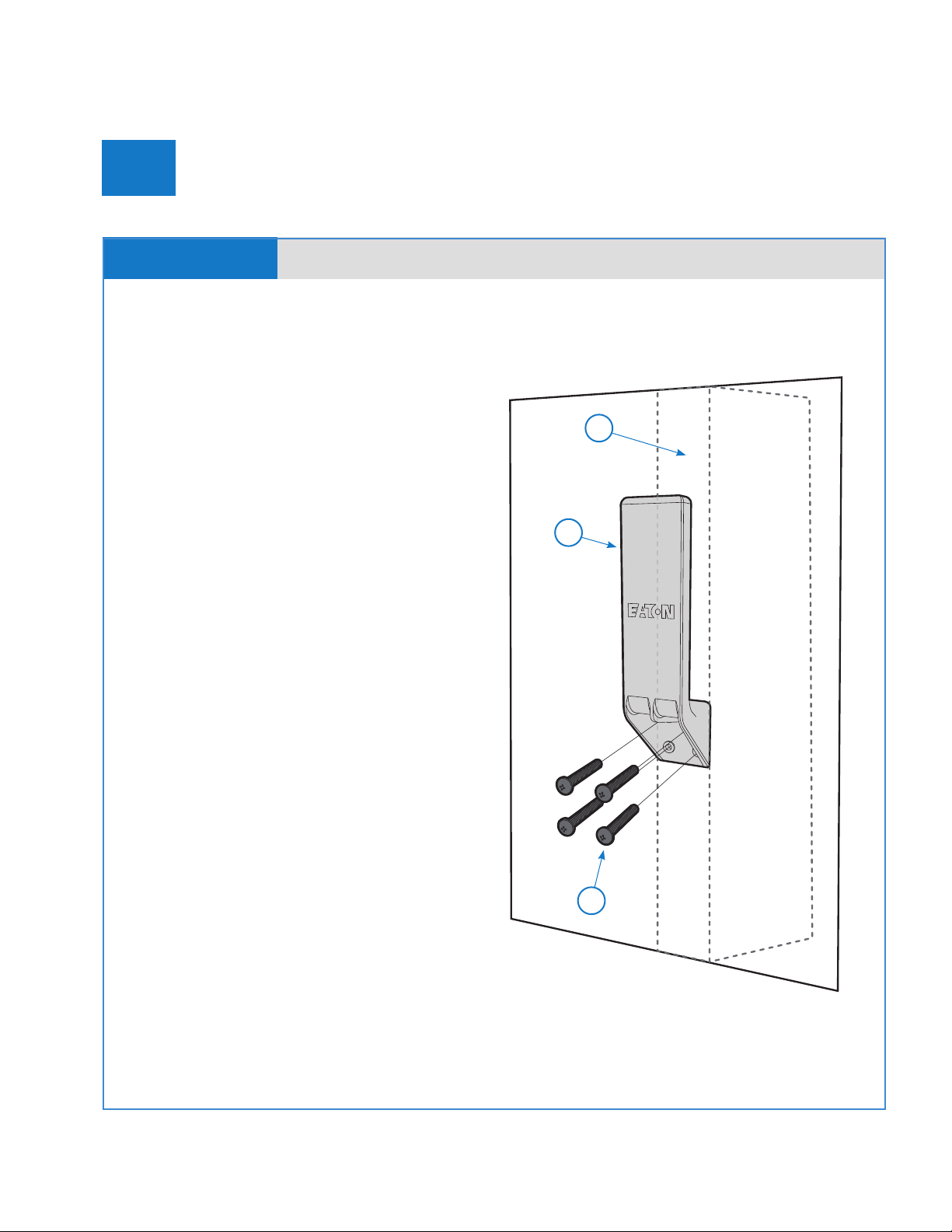
Install the cord management bracket
E
STEP E-1 EV direct connect and junction box kits
The cord management bracket is necessary for
the EV direct connect kit and EV direct connect +
junction box kit.
If mounting bracket to a drywall surface:
• Locate the center of the stud where you wish to
install the bracket.
Note: Please reference the ADA website for
accessibility requirements.
• Using the cord management bracket (1) as a
template, precisely align two holes of the bracket
(right or left side) along the center line of the stud (2)
and mark each of the four mounting holes.
• Using the marks aligned with the stud, pre-drill a
1/8-inch hole at both of the hole locations to a depth
of 5/8 inches.
• For the other two holes (the ones not aligned with
the stud), drill a clearance hole to the size specified
for an appropriate drywall anchor or toggle bolt.
• Install the two drywall anchors or toggle bolts to the
holes.
• Attach the cord management bracket to the wall
using four #10 x 1-1/2 inch Phillips pan head
screws (3).
If mounting bracket to a plywood or similar surface:
• Determine where you wish to install the bracket.
• Mark screw hole locations (four locations on 1-inch
centers).
• Using the marks, pre-drill a 1/8-inch hole at each of
the four hole locations to a depth of 5/8 inches.
• Attach the cord management bracket to the wall
using four #10 x 1-1/2 inch Phillips pan head screws.
Reference:
1. Cord management bracket
2. Stud
3. #10 woodscrew 1-1/2 inches long - x4
Figure 6
2
1
3

16
Green Motion EV smart breaker chargers
EV DIRECT CONNECT AND JUNCTION BOX KITS www.eaton.com
FCC
FCC ID
This device complies with part 15 of the FCC rules. Operation is subject to the following two
conditions:
1. This device may not cause harmful interference, and
2. This device must accept any interference received, including interference that may
cause undesired operation.
FCC ID: VPYLB1CBIMP003
RF radiation exposure statement
This equipment complies with FCC RF radiation exposure limits set forth for an uncontrolled
environment. This equipment should be installed and operated with a minimum distance of
20 centimeters between the radiator and your body.
Canada low-power license exempt radio
communication devices (RSS-210)
Common information operation is subject to the
following two conditions:
1. This device may not cause interference, and
2. This device must accept any interference, including interference that may cause unde-
sired operation of the device.
IC: 772CVLB1CDIMP003
17
Installation Guide: EV direct connect and junction box kits
EV DIRECT CONNECT AND JUNCTION BOX KITS www.eaton.com
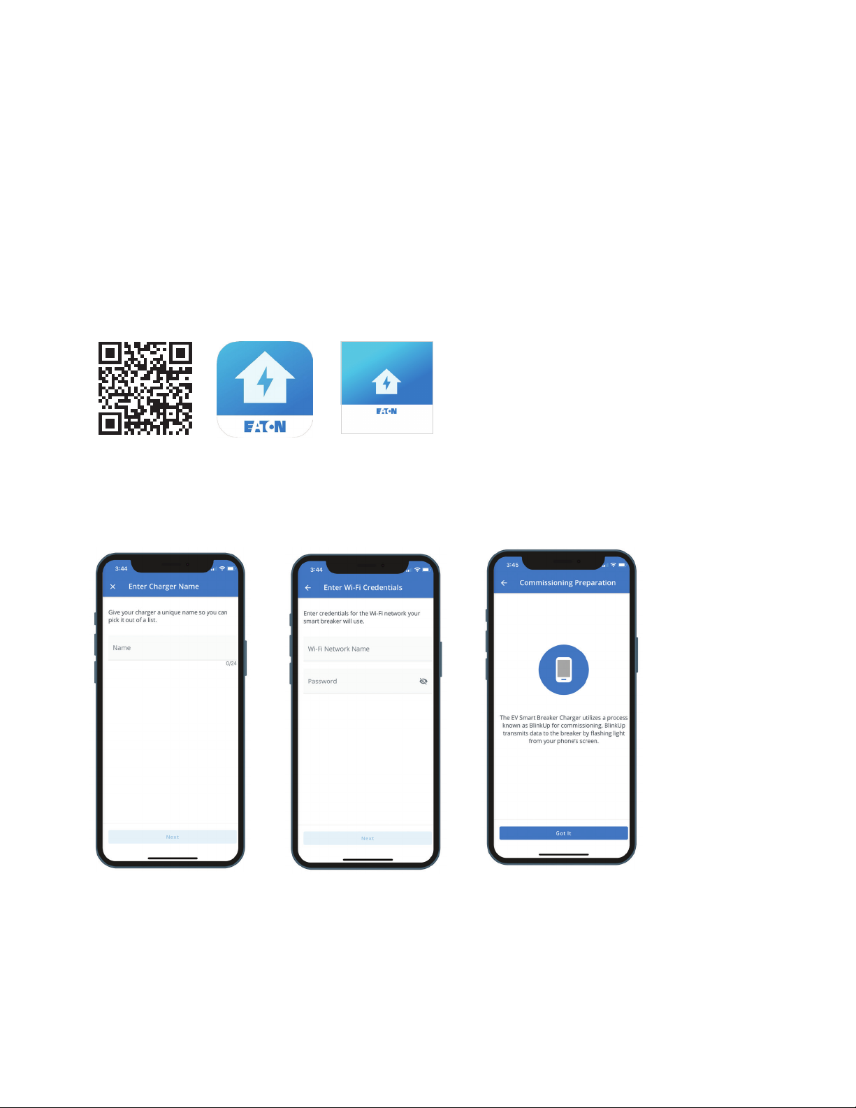
Connect to Wi-Fi
Wi-Fi commissioning and operation
After the EV smart breaker charger has been successfully installed and power has been
restored to the loadcenter or panelboard, the EV smart breaker charger must be commis-
sioned. Ensure that a Wi-Fi signal is available where the EV smart breaker charger has been
installed.
Get started by downloading the Green Motion EV Charger Manager app. Available on IOS
and Google Play stores.
• Name your charger
• Enter your Wi-Fi credentials
• Connect your breaker following the steps in the app
To use the EV smart breaker charger with your preferred charge management system,
please visit our developer portal (www.Eaton.com/developer) for complete API documenta-
tion. Once the integration is complete, download the EM Install app to commission the EV
smart breaker charger.

18
Green Motion EV smart breaker chargers
EV DIRECT CONNECT AND JUNCTION BOX KITS www.eaton.com
Technical specifications
Catalog number GMEV32BR-DC, GMEV32BAB-DC, GMEV32BR-JB, GMEV32BAB-JB
Electrical input
Input power 7.7 kW
Input voltage 208/240 Vac
Input breaker rating 40 A
Electrical output
Power output 7.7 kW
Output voltage 208/240 Vac
Output amperage 32 A
Connector SAE J1772
Installation Directly installs in an Eaton BR loadcenter or PRL3X panelboard
Cable length (in feet) 25
Safety UL
Interlocked power protection Yes
Ground fault protection 20 mA
Overcurrent protection Yes
Automatic reset after
nuisance trip feature
Yes
Randomized restart on power
failure (delay before charging
resumes after a power failure)
Yes
Frequency rating 60 Hz
Storage temperature –40 °C to +60 °C
Ambient operating temperature –30 °C to +40 °C
Humidity 0% to 90%, noncondensing
kAIC rating 10 kA
Warranty Seller warrants that the Products manufactured by it will conform to Seller’s applicable specifications and be free from failure due
to defects in workmanship and material for three (3) years from the date of original purchase, installation of the Product, or from
the date of shipment of the Product, whichever occurs first. In the event any Product fails to comply with the foregoing warranty,
Seller will, at its option, either (a) repair or replace the defective Product, or defective part or component thereof, F.O.B. Seller’s
facility freight prepaid, or (b) credit Buyer for the purchase price of the Product. All warranty claims shall be made in writing. Seller
requires all non-conforming Products be returned at Seller’s expense for evaluation unless specifically stated otherwise in writing
by Seller. This warranty does not cover failure or damage due to storage, installation, operation or maintenance not in conformance
with Seller’s recommendations, including as set forth in these Terms and Conditions of Sale, and industry standard practice or due to
accident, misuse, abuse, or negligence. This warranty does not cover breach of data or system security, including that of information
technology infrastructure, computers, software, hardware, databases, electronic systems (including database management systems),
and networks. This warranty does not cover reimbursement for labor, gaining access, removal, installation, temporary power or any
other expenses, which may be incurred in connection with repair or replacement. This warranty does not apply to equipment not
manufactured by Seller. Seller limits itself to extending the same warranty it receives from the third-party supplier, to the extent such
third party permits assignment of its warranty. For other general terms and conditions of sale, please refer to Eaton’s selling policy
25-000.
Certifications UL 489—Molded case circuit breakers, molded case switches, and circuit breaker enclosures
UL 2231—These requirements cover devices and systems intended for use in accordance with the National Electrical Code (NEC),
ANSI/NFPA 70, Article 625, to reduce the risk of electric shock to the user from accessible parts, in grounded or isolated circuits for
charging electric vehicles. These circuits are external to or on-board the vehicle
UL 1998—These requirements apply to non-networked embedded software residing in programmable components performing
safety-related functions whose failure is capable of resulting in a risk of fire, electric shock, or injury to persons
UL 2251—Plugs, receptacles, and couplers for electric vehicles
UL 2594—Electric vehicle supply equipment
Energy Star Level 2 Certified charger
CSA® C22.2 No. 5—Molded case circuit breakers, molded case switches and circuit breaker enclosures
SAE J1772 2017 Ed.
NFPA 70 Article 625
FCC Compliant, Part 15
Description Specification
Other manuals for Green Motion
1
Table of contents
Other Eaton Automobile Accessories manuals

Eaton
Eaton VORAD AlwaysAlert User manual

Eaton
Eaton Green Motion Fleet User manual

Eaton
Eaton Green Motion DC 22 User manual

Eaton
Eaton xChargeIn Mobility User manual

Eaton
Eaton Green Motion Building User manual

Eaton
Eaton green motion xChargeIn Mobility User manual

Eaton
Eaton VORAD User manual

Eaton
Eaton Green Motion DC 22 Installation guide

Eaton
Eaton gree motion xChargeIn DC 22 User manual

Eaton
Eaton xChargeIn Instruction Manual


