Minuteman BPRTXL Series User manual

Para Systems, Inc.
1455 Lemay Dr.
Carrollton, TX 75007
Phone: 1-972-446-7363
Fax: 1-972-446-9011
Internet: minutemanups.com
UPS Sizing: sizemyups.com
P/N 34000433 R4
User's Manual
BPRTXL Series
Battery Packs

1
© Copyright 2013
1. Introduction 2
2. Controls and Indicators 6
3. Installation 7
4. Operation 14
5. Troubleshooting 15
6. Replacing the Battery 16
7. Obtaining Service 20
8. Specifications 21
9. Limited Product Warranty 22

23
IMPORTANT SAFETY INSTRUCTIONS
SAVE THESE INSTRUCTIONS !
Thankyouforpurchasingthispowerprotectionproduct. Ithasbeendesigned
andmanufacturedtoprovidemanyyearsoftroublefreeservice.
Pleasereadthis manual before installing your BPRTXL Battery Pack, models
BP24RTXL, BP36RTXL, BP48RTXL, BP72RTXL as it provides important in-
formation that should be followed during installation and maintenance of the
Battery Packs and batteries allowing you to correctly set up your system for
the maximum safety and performance. Included is information on customer
support and factory service if it is required. If you experience a problem with
the Battery Packs please refer to the Troubleshooting guide in this manual to
correct the problem or collect enough information so that the Technical Sup-
port Department can rapidly assist you.
Thissymbol indicates "ATTENTION"
This symbol indicates "Risk of Electrical Shock"
This symbol indicates "Alternating Current Supply"
This symbol indicates "Alternating Current Supply Phase" WARNING: Riskof Electrical Shock. Hazardouslivepartsinside
these Battery Packs are energized from the battery even when the
AC input is disconnected.
CAUTION! This Battery Pack series is ONLYintended to be in-
stalled in an indoor temperature controlled environment that is free
of conductive contaminants. This Battery Pack series is not for use
in a computer room as defined in the Standard for the Protection of
Electronic Computer/Data Processing Equipment ANSI/NFPA 75.
Select a location which will provide good air circulation for the Bat-
tery Pack and UPS at all times.
CAUTION! Connect the Battery Pack to a two pole, three wire,
groundedACwalloutlet. Theoutlet must be connected to the appro-
priate branch protection (circuit breaker or fuse). Connection to
any other type of outlet may result in a shock hazard and violate
local electrical codes. TheAC wall outlet shall be installed near the
Battery Pack and shall be easily accessible. The plug on the input
power cord on this Battery Pack series is intended to serve as a
disconnect device. Do not use extension cords, adapter plugs, or
surge strips.
CAUTION! To reduce the risk of electrical shockwith the installa-
tion of these Battery Packs, with the UPS equipment and the con-
nected equipment, the user must ensure that the combined sum of
theAC leakage current does not exceed 3.5mA.
This symbol indicates "Direct Current Supply"
This symbol indicates "Equipment Grounding Conductor"
WARNING: These Battery Packs contains potentially hazardous
voltages. Do not attempt to disassemble the Battery Pack beyond
thebatteryreplacementprocedure. TheseBatteryPacks contain no
user serviceable parts. Repairs and Battery replacement must be
performedby QUALIFIED SERVICEPERSONNELONLY.
CAUTION! DO NOT USE THE MOUNTING BRACKETS TO
LIFT THE BATTERY PACK. The mounting brackets are ONLYfor
securing the Battery Pack to the rack.

45
Receiving Inspection
Once you receive the product it should be visually inspected for damage that
may have occurred in shipping. Immediately notify the carrier and place of
purchase if any damage is found. Warranty claims for damage caused by the
carrier will not be honored by the manufacturer. The packing materials that
the product was shipped in were carefully designed to minimize any shipping
damage. In the unlikely case that the product needs to be returned to the
manufacturer, use the original packing material. Since the manufacturer is
not responsible for shipping damage incurred when the product is returned,
the original packing material is inexpensive insurance. PLEASE SAVE THE
PACKING MATERIALS!
NOTICE: This equipment has been tested and found to comply with
thelimits for aClassAcomputingdevice in accordance with the speci-
ficationsin SubpartJofPart 15 of FCC Rules and the ClassAlimits for
radionoise emissions fromdigitalapparatus set outinthe Radio Interference of
the Canadian Department of Communications. These limits are designed to
providereasonable protectionagainstsuch interference inaresidential installa-
tion. This equipment generates and uses radio frequency and if not installed
andusedproperly, that is, in strict accordance with the manufacturer's instruc-
tions,this equipment may cause interference to radio and television reception.
Ifthis equipment doescauseinterference to radio ortelevisionreception, which
canbe determined by turningtheequipment off and on, theuseris encouraged
to try to correct the interference by one or more of the following measures:
Re-orientthe receivingantenna.
Relocatethecomputerwithrespect to the receiver.
Movethe computer away from thereceiver.
Plugthecomputerintoadifferent outlet so that the computer and receiver
areon different branch circuits.
Shieldedcommunications interface cables must be used withthisproduct.
WARNING: Changes or modifications to this unit not expressly ap-
proved by the party responsible for compliance could void the user's
authoritytooperatetheequipment.
Life Support Policy
Asa general policy,wedonotrecommendthe use of any of our productsinlife
supportapplications where failure or malfunctionoftheproduct can be reason-
ablyexpected to cause failure of the life support device or tosignificantlyaffect
its safety or effectiveness. We do not recommend the use of any of our prod-
ucts in direct patient care. We will not knowingly sell our products for use in
such applications unless it receives in writing assurances satisfactory to us
that (a) the risks of injury or damage have been minimized, (b) the customer
assumes all such risks, and (c) our liability is adequately protected under the
circumstances.
Examplesof devices consideredtobe life supportdevicesare neonatal oxygen
analyzers,nerve stimulators (whether used for anesthesia, pain relief, or other
purposes), auto transfusion devices, blood pumps, defibrillators, arrhythmia
detectorsandalarms,pacemakers,hemodialysissystems,peritonealdialysis
systems,neonatal ventilator incubators, ventilators for both adults and infants,
anesthesiaventilators, and infusion pumps as well as anyotherdevicesdesig-
nated as “critical” by the United States FDA.
WARNING: Qualified Service Personnel ONLY must perform
theInstallationand Servicing of these Battery Packs. MINUTEMAN
accepts no liabilities and is not limited to: injury to the Service Per-
sonnel,ordamages to; the Battery Pack, the UPS, or the connected
equipment caused by the incorrect installation or servicing of the
Battery Packs. These Battery Packs MUST be operated with their
respectiveUPS models, see the table below:
BP36RTXL
UPS E750RTXL2U
E1000RTXL2U
E1500RTXL2U
E1500RTXLT2U
E750RTXL2Up15
BP BP72RTXL
E2000RTXL2U
E3000RTXL2U
E3000RTXLT2U
E2000RTXL2UL
ED3000RTXL2U
ED3000RTXLT2U
BP24RTXL BP48RTXL
ED1000RTXL2U
ED1000RTXLT2U ED1500RTXL2U
ED1500RTXLT2U
ED2000RTXL2U
ED2000RTXLT2U
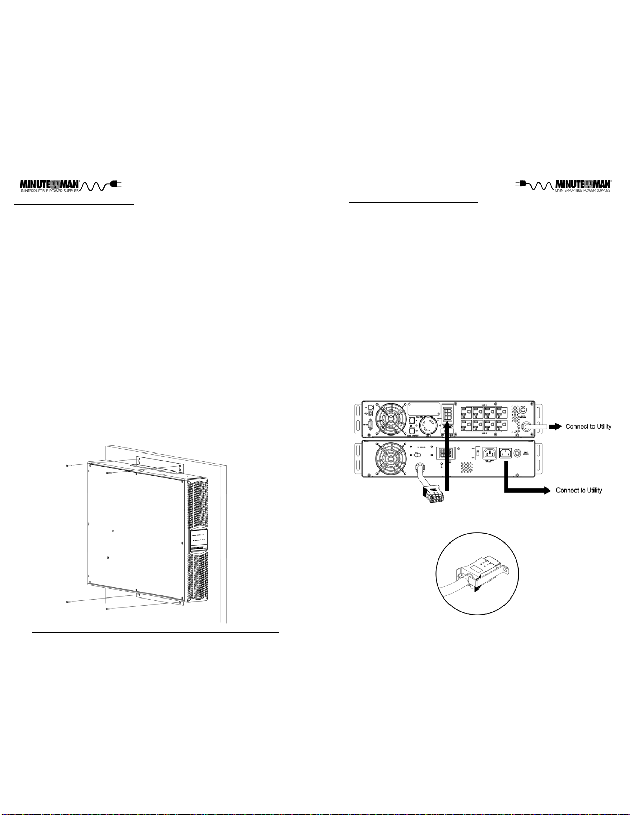
CAUTION! To de-energize the Battery Pack:
1. If the UPS is on press and release the On/Off/Test button.
2. Disconnect the UPS and the Battery Pack from the wall outlet.
3. Turnoff the DC breaker on the rear panel of the Battery Pack.
4. Disconnect the battery cable from the rear panel of the UPS.
5. To de-energize the Battery Pack completely, disconnect the bat-
teries.

67
The Charger Active (green) LED illuminates in a steady state when the Charger is
on. The Charger Active LED will extinguish when there is no acceptable AC present.
The DC Breaker On (green) LED illuminates in a steady state when the DC breaker
is in the On position. The DC Breaker On LED will extinguish when the DC breaker
is in the Off position.
INDICATOR PANEL
REAR PANEL
1. The DC Circuit Breaker connects and disconnects the DC bus voltage from the
Battery Pack to the UPS. The DC Circuit Breaker will trip in the event of a DC over-
current condition.
2. The External Battery connector is for Daisy Chaining additional Battery Packs.
3. The dipswitch is for setting the input voltage for the Battery Pack's internal charger.
4. The AC Outlet is for connecting the output cable to Daisy Chain additional Battery
Packs.
5. The AC Inlet is for connecting the input power cord to operate the Charger.
6. The Input Breaker will trip in the event that the Internal Charger draws excessive
current.
7. The External Ground Stud is for connecting an external ground wire.
8. The External Battery cable is for connecting the Battery Pack to the UPS or Daisy
Chaining additional Battery Packs.
INSTALLATION PLACEMENT
This Battery Pack series is ONLYintended to be installed in an indoor tem-
perature controlled environment that is free of conductive contaminants. DO
NOToperatetheBatteryPackin:extremelydustyand/oruncleanareas,loca-
tions near heating devices, water or excessive humidity, or where the Battery
Pack is exposed to direct sunlight. Select a location, which will provide good
air circulation for the Battery Pack at all times.
Route power cords so they
cannot be walked on or damaged. This Battery Pack series is not for use in a
computer room as defined in the Standard for the Protection of Electronic
Computer/DataProcessing EquipmentANSI/NFPA75. Typical battery life is 3
to 5 years. Environmental factors do affect battery life. High temperatures,
poor utility power, and frequent, short duration discharges have a negative
impact on battery life.
INSTALLATION
Besure to read the installation placement and all the cautions before installing
the Battery Pack. Place the Battery Pack in the final desired location and
completethe rest of the installation procedure.
WARNING! These Battery Packs are extremely heavy. Any time
theBattery Pack has to be handled be sure to use, enoughperson-
nel,strongsupportsandequipmentto safelyhandle theBattery Pack.
ENVIRONMENTAL
OperatingTemperature(max)
Operating/Storage Humidity
OperatingElevation
0 to 40°C (+32 to +104°F)
95%Non-Condensing
0 to 3,000m (0 to +10,000 ft)
StorageElevation 0 to 15,000m (0 to +50,000 ft)
StorageTemperature -15 to +45°C (+5 to +113°F)
Audible Noise at 1 m (3 ft.) <45 dBA
CAUTION! DO NOT USE THE MOUNTING BRACKETS TO LIFT
THE BATTERY PACK. The mounting brackets are ONLYfor se-
curing the Battery Pack to the rack.

89
RACKMOUNTCONFIGURATION
TheBattery Pack comes with mounting bracketsforthestandard 19" (46.5cm)
rackinstalled on the Battery Pack. The mounting brackets to fita23"(59.2cm)
rack and Rail Kits for 4-post racks and cabinets are also available. The
screws for mounting the Battery Pack to the rack are included.
TOWER CONFIGURATION
The tower configuration allows the user to install the Battery Pack in the up-
rightpositionnext to the UPS and the tower computer. Thetowerbracketsare
provided with the Battery Pack. WARNING: Use two or more people when
installing the Battery Pack. Use CAUTION, the Battery Pack is extremely
heavy.
1. TheBatteryPackscome with the rackmount brackets pre-installed. Remo-
ve the rackmount brackets when installing in the Tower Configuration.
2. Once the location of the Battery Pack has been determined, place the
tower brackets in the desired location.
WARNING: The Battery Pack must be installed in the proper up-right posi-
tion. If the Battery Pack is not installed in the proper up-right position the
Batteries will be damaged. Once the Battery Pack is placed in the tower
brackets, looking at the front panel of the Battery Pack the top cover of the
Battery Pack MUST be on your left hand side.
3. Slide the Battery Pack into the tower brackets. Make sure that the Battery
Pack is stable.
4. TheLEDfaceplatecan be rotated to read in the up-right position. Remove
the front panel from the Battery Pack. On the backside of the front panel,
push the LED face plate outwards the face plate will pop out. Position the
LED face plate so that it reads in the up-right position. Re-install the front
panel on the Battery Pack.
5. The Tower Configuration is complete. See Connecting the Battery Pack.
WALLMOUNT CONFIGURATION
The wallmount configuration allowsthe user to mount the Battery Pack on the
wall. There is a wallmount bracket kit available for the Battery Pack. The kit
includes two wall mounting brackets, ten retaining screws, and the wallmount
template. WARNING: Use two or more people when installing the Battery
Pack. Use CAUTION, the Battery Pack is extremely heavy. The Battery
Pack's side panels have mounting bracket screw holes for attaching the wall
mountingbrackets.
1. TheBatteryPackscome with the rackmount brackets pre-installed. Remo-
ve the rackmount brackets when installing in the Wallmount Configuration.
2. Once the location and position of the Battery Pack has been determined,
lay the Battery Pack down flat.
CAUTION! DO NOT USE THE MOUNTING BRACKETS TO LIFT
THE BATTERYPACK. The mounting brackets areONLYfor secur-
ing the Battery Pack to the rack.
NOTE: The mounting brackets can be mounted in the middle of the Battery
Pack.
1. Remove the Battery Pack from the shipping box.
2. Mount the Battery Pack into the rack and secure with the retaining screws.
WARNING: Use two or more people when installing the Battery Pack. Use
CAUTION, the Battery Pack is extremely heavy. Do not move the rack
after the units have been installed. The rack may become unstable due to
the weight distribution.
3. The Rackmount Configuration is complete. See Connecting the Battery
Pack.

10 11
WALLMOUNT CONFIGURATION (continued)
WARNING: The Battery Pack must be installed in the proper up-right posi-
tion. If the Battery Pack is not installed in the proper up-right position the
Batteries will be damaged. Once the Battery Pack is placed on the wall,
looking at the front panel of the Battery Pack the top cover of the Battery Pack
MUST be on your left hand side.
3. Align the mounting brackets with the mounting bracket screw holes and
attach with the six retaining screws.
4. Use the template to mark the screw hole position on the wall. CAUTION,
you should always were protective gear for your hands and eyes when
operating power tools.
5. Attach the four retaining screws to the wall and make sure that all of the re-
taining screws are screwed into structural material. Then clean the area
of any loose material. Do not tighten the retaining screws all the way, leave
approximately 3/8" of the retaining screws sticking out.
6. PositiontheBatteryPack,sothat the mounting bracket keyed holes line up
with the four retaining screws. Slide the Battery Pack down until its resting
securely on the four retaining screws.
7. Tighten the four retaining screws to secure the Battery Pack to the wall.
8. TheLEDfaceplatecan be rotated to read in the up-right position. Remove
the front panel from the Battery Pack. On the backside of the front panel,
push the LED face plate outwards the face plate will pop out. Position the
LED face plate so that it reads in the up-right position. Re-install the front
panel on the Battery Pack.
9. The Wallmount Configuration is complete. See Connecting the Battery
Pack.
CONNECTINGTHE BATTERYPACK
(QUALIFIEDSERVICE PERSONNELONLY)
NOTE: If you are using these Battery Packs with the Enterprise Plus LCD
RTXL series or the Endeavor LCD RTXL series UPS, the UPS must be
configured so that the UPS will report the correct estimated runtime on
the LCD screen and in the Power Monitoring software and/or the SNMP
card. See the Power Monitoring software or the SNMP card’s User's
Manual to configure the UPS.
1. Make sure that the DC circuit breaker on the rear panel of the Battery Pack
is in the Off position.
2. Turn the UPS off and disconnect the UPS's input power cord from theAC
wall outlet.
3. RemovetheExternalBatteryConnectorcoverfromtheUPS's rear panel.
4. Verify, before connecting the Battery Pack's external battery cable into the
UPS's external battery connector, that they mate red to red and black to
black. NOTE: The red connector is the battery positive (+) and the black
connector is the battery negative (-). Connect the external battery cable
from the Battery Packtothe external battery connector ontheUPS. NOTE:
If connecting more than one Battery Pack see Daisy Chaining.
5. See Connecting the Battery Pack to anAC Source.
NOTE: The BP72RTXL's External Battery Cable has a strain relief that
must be attached (with the screw) to the rear panel of the UPS.
BP72RTXL's External Battery Cable with strain relief.

12 13
CONNECTING THE BATTERYPACK TO AN AC SOURCE
These Battery Packs can operate with 115VAC or 230VAC input voltage. Before
connectingtheBatteryPack toanACSource,verify thattheBatteryPack's dipswitch
isset for the proper input voltage.
1. Set the dipswitch on the rear panel of the Battery Pack to the appropriate input
voltage.
2. Connectthe input power cord forthe Battery Pack into theAC Inlet on therear
panel of the Battery Pack.
3. Plug the other end of the input power cord for the Battery Pack into theAC wall
outlet,use a two pole, three wire, groundedACwall outlet. TheAC wall outlet
shall be near the Battery Pack and shall be easily accessible. The plug on the
input power cord on this Battery pack series is intended to serve as a discon-
nect device. Do not use extension cords, adapter plugs, or surge strips.
4. Turn the DC circuit breaker to the On position. See the UPS User's Manual for
the normal startup of the UPS. NOTE: If connecting more than one Battery
Pack see Daisy Chaining.
CHARGING THE BATTERY
TheBattery Packs willcharge the internalbatteries whenever the BatteryPack is
connected to anAC source and there is an acceptableAC voltage present. It is
recommendedthat theBattery Packsbe chargedfor aminimum of4hours before
use. TheBatteryPackmaybeusedimmediately,however,the“On-Battery” runtime
of the UPS may be less than normally expected. NOTE: If the Battery Pack is
going to be out of service or stored for a prolonged period of time, the batteries
mustbe rechargedfor atleast 24hours everyninety days.
DAISYCHAINING
(QUALIFIEDSERVICEPERSONNELONLY)
"DaisyChaining" means hooking one Battery Pack to another Battery Pack to
another Battery Pack, this chain could go on indefinitely. Follow the steps
below to Daisy Chain the Battery Packs.
1. Besure to read the installation placement procedure, all of the cautionsand
the safety precautions before Daisy Chaining the Battery Pack(s).
2. Makesurethatall,theBatteryPack'sDCcircuitbreakersand UPS's power
switch, are in Off position. CAUTION: If the Battery Pack's DC circuit bre-
aker is in the On position, the battery voltage will be present at the open
end of the Battery Pack's external battery cable and external battery conn-
ector. Unplug all the equipment that is plugged into the UPS's output rece-
ptacles. Disconnect the power cords, that are on the Battery Packs and
the UPS, from the AC wall outlet.
3. Removethe ExternalBattery Connector coverfrom theUPS'srear paneland
the additional Battery Packs.
4. Verify, before plugging the external battery cable into the UPS's external
battery connector or the Battery Pack's external connector that they mate
red to red and black to black.
5. Connect the external battery cable from the first Battery Pack to the exter-
nal battery connector on the UPS.
6. Connecttheexternal battery cable from the second Battery Pack to the ex-
ternal battery connector on the first Battery Pack.
7. Before connecting the Battery Pack to an AC Source, verify that the Bat-
tery Pack is set for the proper input voltage. Set the dipswitch on the rear
panel of the Battery Pack to the appropriate input voltage. Connect the
input power cord with the NEMA 5-15P Plug into theAC Inlet on the first
Battery Pack.
8. Connect the Daisy Chain power cord from the AC Outlet of the of the first
Battery Pack to the AC Inlet of the second Battery Pack.
9. Connect the input power cord (with the NEMA 5-15P Plug) from the first
Battery Pack into the AC wall outlet, use a two pole, three wire, grounded
ACwall outlet. TheACwall outlet shallbenear the UPS and shall be easily
accessible.
10. TurnALLof the DC circuit breakers on the rear panel of the Battery Packs
to the On position.
11. The Battery Packs are ready for normal operation, see the UPS User's
Manualfor the normal startup ofthe UPS.
NOTE: Themaximumnumber that can be Daisy Chained for theAC source is
five Battery Packs. There is no maximum number for Daisy Chaining the DC
bus voltage for the Battery Packs.
NOTE: The BP72RTXL's External Battery Cable has a strain relief that
must be attached (with the screw) to the rear panel of the UPS.
BP72RTXL's External Battery Cable with strain relief.

14 15
English
SYSTEM OVERVIEW
TheseBattery Packswill extendthe runtimecapabilities ofthe UPS. TheseBattery
Packshaveinternalchargers toproperlymaintain the internalbatteries. Thecharger
will operate with 115VAC or 230VAC depending on the dipswitch setting. The
Battery Pack will charge the batteries with the DC circuit breaker in the On or Off
position as long as the Battery Pack is plugged into theAC wall outlet and there is
an acceptableAC voltage present (90 - 130VAC/180 - 260VAC). When the com-
mercial power is lost the charger will turn Off and the Battery Pack will extend the
runtimeof the UPS. When thecommercial power returns theBattery Pack's inter-
nalcharger will automaticallystart recharging the batteries. During normalAC op-
eration,the UPS and BatteryPack will quietly and confidently protect your system
frompower anomalies.
TURNING THE BATTERYPACK ON/OFF
Turning the DC circuit breaker to the On position will connect the DC bus voltage
fromthe BatteryPack tothe UPS. Turningthe DC circuit breaker tothe Offposition
will disconnect the DC bus voltage from the Battery Pack to the UPS. The DC
circuit breaker does NOT turn on or turn off the internal charger. Plug the input
powercord into theAC wall outlet toturn on the internalcharger. Unplugthe input
powercord to turn off the internal charger. The Battery Pack's internalcharger will
continue to charge the batteries whenever it is plugged into anAC wall outlet and
there is an acceptableAC voltage present (90 - 130VAC/180 - 260VAC).
DIPSWITCH SETTINGS
Thedipswitch setting may be changed by the user toset the desired inputvoltage
for the Battery Pack's internal charger. The dipswitch must be set with the DC
circuitbreaker in the Offposition and with theinput power cord disconnectedfrom
theAC wall outlet. Set the dipswitch to 115VAC or 230VAC. Plug the input power
cord into theAC wall outlet and turn the DC circuit breaker to the On position.
INDICATORS
TheChargerActive(green) LED illuminates in a steady statewhen the Charger is
on. TheChargerActive LED will extinguish when there is noAC present.
TheDC Breaker On (green) LED illuminates in a steady state when the DC circuit
breakeris inthe On position. The DC BreakerOn LED will extinguish whenthe DC
circuit breaker is in the Off position.
PossibleCause
Symptom What To Do
1. Plug the input power cord
intotheAC wall outlet.
2. Once commercial power is
available recheck the LED.
3.Check the circuit breaker at
the service panel to see if it is
tripped.
4. Call for Service.
1. The input power cord is
notplugged into theAC wall
outlet.
2. No commercial power
available.
3. No AC voltage at the AC
walloutlet.
4.Internal chargerfault.
The ChargerActive
LED is not on.
1. Turn the DC circuit breaker
to the On position.
2. Reset the DC circuit
breaker.
3. Reconnect the internal bat-
terywires.
4. Call for Service.
1. The DC circuit breaker is
in the Off position.
2. The DC circuit breaker is
tripped.
3.The internal battery wires
are disconnected.
4.Internal fault.
TheDC Breaker On
LED is not on.
1. Plug the input power cord
intotheAC wall outlet.
2.Set the dipswitch to the cor-
rectsetting.
3. Call for Service.
1. The input power cord is
notplugged into theAC wall
outlet.
2.The dipswitchis not setto
thecorrect input voltage.
3.The charger has an inter-
nalfault.
The charger is not
providingthecorrect
chargevoltage.
Block Diagram of the Basic Wiring and Internal Circuit Configuration

16 17
REPLACING THE BATTERY
WARNING! ThisBatteryPackcontainspotentiallyhazardousvoltages. Do
not attempt to disassemble the Battery Pack beyond the bat-
tery replacement procedure. These Battery Packs contain no
userserviceableparts. RepairsandBatteryreplacementmust
beperformed byQUALIFIED SERVICE PERSONNELONLY.
Donot open or mutilatebatteries. Releasedelectrolyte is harm-
ful to the skin and eyes and may be toxic.
CAUTIONS:
(QUALIFIEDSERVICEPERSONNELONLY)
Donot dispose of batteriesinafire. The batteries may explode.
The batteries in this Battery Pack are recyclable. Dispose of
the batteries properly. The batteries contain lead and pose a
hazardtotheenvironment and human health if not disposed of
properly. Refer to local codes for proper disposal requirements
or return the battery to the supplier.
Thebattery system can still present a risk of electricalshock. These batteries
produce sufficient current to burn wire or tools very rapidly, producing molten
metal. Observetheseprecautionswhenreplacingthebatteries:
1. Remove watches, rings, or other metal objects.
2. Use hand tools with insulated handles.
3.Wear protective eye gear (goggles), rubber gloves and boots.
4. Do not lay tools or other metal parts on top of batteries.
5. Disconnect the charging source prior to connecting or disconnecting the
battery terminals.
6.Determineif the battery is inadvertently grounded. If the battery is, remove
the source of the grounding. Contact with any part of a grounded battery
can result in an electrical shock. The likelihood of such shock will be re-
duced, if such grounds are removed during installation and maintenance.
TheseBattery Packs have aneasyto replace hot-swappable batteries. Please
read all of the WARNINGS and CAUTIONS before attempting to service the
batteries. Typical battery life is 3 to 5 years. Environmental factors do affect
batterylife. High temperatures, poor utility power,and frequent, short duration
discharges have a negative impact on battery life. NOTE: If there is a power
interruption while replacing the hot-swappable batteries, with the UPS on, the
load will not be backed up.
BATTERYREPLACEMENT PROCEDURE
(QUALIFIEDSERVICEPERSONNELONLY)
PLEASE READ THE CAUTIONS AND WARNINGS BEFORE ATTEMPTING
TOREPLACETHE BATTERYMODULES
Hot-swappable batteries mean that the batteries can be replaced without
poweringdownthewholeUPSsystem.
NOTE: Ifthere isa power interruptionwhile replacing thehot-swappable batter-
ies, with the UPS on, the load will not be backed up. To hot-swap the Battery
Pack's battery modules start with step number 6.
1. Turn off the equipment that is plugged into the output receptacles of the
UPS.
2. PressandreleasetheOn/Off/Test button on the front paneltoturntheUPS
off.
3. Unplug the UPS'sAC power cord from theAC wall outlet.
4. Unplug the equipment from the output receptacles of the UPS.
5. Unplug the computer interface cable from the rear panel of the UPS.
6. Turn off all of the DC circuit breakers on the rear panel of all of the Battery
Packs.
7. Unplug all of the Battery Pack's AC power cords from theAC wall outlet.
8. Disconnect all of the external battery cables.
9. Remove the front panel retaining screws. (FIG. 2)
10. Lay the front panel on top of the Battery Pack.
11. Remove the retaining screws for the battery retaining brackets. (FIG. 3)
12. Remove the battery retaining brackets. (FIG. 3)
13. Disconnectthe battery connectors (red and black) fromeachofthebattery
modules. (FIG. 4)
14. Grasponeofthebatterypulltabsandgentlypullthebatterymoduleoutof
the Battery Pack and set on the floor. (FIG. 4)
15. Grasp the other battery pull tab and gently pull the battery module out of
the Battery Pack and set on the floor. (FIG. 4)
NOTE: UseCaution,thebatterymodulesareheavy.
Replacethe batteries with the same number and type as originally
installedin the Battery Pack. These batteries have pressure oper-
ated vents. These Battery Packs contain sealed non-spillable
maintenancefree lead acid batteries.
CAUTION:
BP36RTXL
Internal
Battery
Module
Part #
BM0033
Model # BP72RTXL
BM0034
BP24RTXL BP48RTXL
BM0038 BM0039

18 19
16. Slide the new battery modules into the Battery Pack.
17. Verify proper polarity. Reconnect the battery connectors (red and black).
NOTE: Some sparking may occur this is normal.
18. Re-install the battery retaining brackets.
19. Re-install the retaining screws for the battery retaining brackets.
20. Re-install the front panel on the Battery Pack.
21. Re-installthe front panel retaining screws.
22. Reconnect all of the external battery cables.
23. Plug in all of the Battery Pack'sAC power cords into the AC wall outlet.
24. Turnon all of the DC circuit breakerson the rear panel of all of the Battery
Packs.
25. Properly dispose of the old batteries at an appropriate recycling facility or
return them to the supplier in the packing material for the new batteries.
26. The Battery Pack is ready for normal operation.
NOTE: Ifthe UPS has a Weak/BadBatteryAlarm afterreplacing the batteries,
the user must initiate a self test to clear the Weak/Bad Battery Alarm. To
initiate a self test see section 4 "SELF TEST" in the UPS's User's Manual.
FIG. 1
FIG. 2
FIG. 3
FIG. 4

20 21
IF THE BATTERYPACK REQUIRES SERVICE
Battery Type
36VDC
Typical Recharge Time
50 or 60 Hz, +/-6Hz, autosensing
115VAC: 90 - 130VAC (230VAC: 180 - 260VAC)
2.6 Amps
41.4VDC +/-5%
Frequency Limits
DCVoltage
Voltage Range
BP36RTXL
ModelNumber SYSTEM SPECIFICATIONS
AC Current
Format Rack/Tower Convertible / Wallmount
CHARGEROUTPUT
CHARGERINPUT
Number of Phases Single (1∅2W +G)
NominalVoltage 115/230VAC (dipswitch selectable)
Input Protection Resettable Circuit Breaker
DCCurrent 2.4 Amps
BATTERYSYSTEM
Typical Battery Life
BM0033
Battery Module
BP72RTXL
82.8VDC +/-5%
System Voltage
Sealed,Non-Spillable, MaintenanceFree, ValueRegulated,LeadAcid
3-5 years, depending on discharge cycles and ambient temp
72VDC
BM0034
Output Protection Resettable Circuit Breaker
PHYSICAL
Weight - Net
Size - Net L X W X H
(rackmount bracket installed)
Size - Shipping
L X W X H
Weight - Shipping
17.0 x 19.0 x 3.5"
432 x 482.6 x 89 mm
23.6 x 21.7 x 9.1"
600 x 551 x 230 mm
REGULATORYCOMPLIANCE
Safety and Approvals
EMCVerification
cUL(UL1778 4th Edition & CSA 22.2no. 107.3-05)
FCC ClassA, CE certified
67.2 lbs
30.5 Kgs
56.0 lbs
25.4 Kgs
27.6VDC +/-5% 55.2VDC +/-5%
49.0 lbs
22.0 Kgs
39.6 lbs
18.0 Kgs 66.0 lbs
30.0 Kgs
75.0 lbs
34.0 Kgs
13.1 x 19.0 x 3.5"
335 x 482.6 x 89 mm
67.2 lbs
30.5 Kgs
56.0 lbs
25.4 Kgs
BM0038 BM0039
24VDC 48VDC
BP24RTXL BP48RTXL
1. UsetheTroubleshootingsection toeliminate obvious causes.
2. Verify there are no tripped circuit breakers and that the batteries are good. A
tripped circuit breaker and defective batteries are the most common issues.
3. Callyour dealer forassistance. Ifyou cannotreach yourdealer,or ifthey cannot
resolvethe issue callor fax theTechnical Support departmentat the following
numbers; Voice phone (972) 446-7363, FAX line (972) 446-9011 or visit our
Web site at www.minutemanups.com the "Discussion Board". Before calling
theTechnical Support Departmenthave thefollowing information available:
a) Contact name and address.
b) Whereand when the unit was purchased.
c) Allof themodel information aboutyour unit.
d) Theserial numberof your unit.
e) Anyinformation on thefailure, including LEDs thatmay be illuminated or
error codes displayed.
f) A description of the protectedequipment includingmodel numbers, if pos-
sible.
g) Atechnician will ask youfor the above information and if possible, help
solvethe issue over the phone. Inthe event thatthe unit requires factory
service,the technicianwill issueyou aReturn MaterialAuthorizationNum-
ber(RMA #).
h) Iftheunit isunder warranty, therepairswill bedone at nocharge. If theunit
isnot under warranty therewill be a charge for the repair.
4. Pack the unit in its original packaging. If the original packaging is no longer
available,ask theTechnicalSupportTechnician about obtaining a new set. Itis
important to pack the unit properly in order to avoid damage in transit. Never
use Styrofoam beads for a packing material.
a) Includea letter with your name,address, day timephone number, RMA
number, a copyof your originalsales receipt,and a briefdescription of the
problem.
5. Mark the RMA# on theoutside of allpackages. The factory cannotaccept any
packagewithout the RMA # marked on the outside.
6. Returnthe unitby insured, prepaid carrier to:
ParaSystems Inc.
MINUTEMANUPS
1809 W. Frankford Road, Suite 150
Carrollton,TX 75007
ATTN: RMA# _______
8-hoursto 90% after full loaddischarge

22 23
Notes:
Para Systems, Inc. (Para Systems) warrants this equipment, when properly applied and
operated within specified conditions, against faulty materials or workmanship for a period
of three years from the date of purchase. For equipment sites within the United States and
Canada, this warranty covers depot repair or replacement of defective equipment at the
discretion of Para Systems. Depot repair will be from the nearest authorized service cen-
ter. The customer pays for shipping the product to Para Systems. Para Systems pays
ground freight to ship the product back to the customer. Replacement parts and warranty
labor will be borne by Para Systems. For equipment located outside of the United States
and Canada, Para Systems only covers faulty parts. Para Systems products that are
depot repaired or replaced pursuant to this warranty shall only be warranted for the unex-
pired portion of the warranty applying to the original product. This warranty applies only to
the original purchaser who must have properly registered the product within 10 days of
purchase.
The warranty shall be void if (a) the equipment is damaged by the customer, is improperly
used, is subjected to an adverse operating environment, or is operated outside the limits of
its electrical specifications; (b) the equipment is repaired or modified by anyone other than
Para Systems or Para Systems approved personnel; or (c) has been used in a manner
contrary to the product’s User's Manual or other written instructions.
Any technical advice furnished before or after delivery in regard to use or application of
Para Systems’ equipment is furnished without charge and on the basis that it represents
Para Systems’ best judgment under the circumstances, but it is used at the recipient’s sole
risk.
EXCEPTASPROVIDEDHEREIN,PARASYSTEMSMAKESNOWARRANTIES,EXPRESSED
ORIMPLIED,INCLUDING WARRANTIESOF MERCHANTABILITYAND FITNESS FORA
PARTICULARPURPOSE. Some states do not permit limitationofimpliedwarranties;there-
fore, the aforesaid limitation(s) may not apply to the purchaser.
EXCEPTAS PROVIDED ABOVE, IN NO EVENTWILL PARA SYSTEMS BE LIABLE FOR
DIRECT,INDIRECT,SPECIAL,INCIDENTAL, OR CONSEQUENTIALDAMAGESARISING
OUTOFTHE USEOFTHISPRODUCT, EVENIFADVISEDOFTHE POSSIBILITYOF SUCH
DAMAGE. Specifically, Para Systems is not liable for any costs, such as; labor for on-site
installation, on-site maintenance or on-site service, lost profits or revenue, loss of equip-
ment, loss of use of equipment, loss of software, loss of data, cost of substitutes, claims by
third parties, or otherwise. The sole and exclusive remedy for breach of any warranty,
expressed or implied, concerning Para Systems’ products and the only obligation of Para
Systems hereunder, shall be depot repair or replacement of defective equipment, compo-
nents, or parts; or, at Para Systems’ option, refund of the purchase price or substitution
with an equivalent replacement product. This warranty gives you specific legal rights and
you may also have other rights which vary from state to state.
Noemployee, salesman, or agent of Para Systems is authorized to add to orvary the terms
of this warranty.
This manual suits for next models
4
Table of contents
Other Minuteman Batteries Pack manuals
Popular Batteries Pack manuals by other brands

Dyness
Dyness POWERCUBE Series user manual

Aegis
Aegis ABL048025P user manual

EnerSys
EnerSys PowerSafe SBS 8 Installation, operation and maintenance manual

Festool
Festool BP 18 Li Series Original instructions

Dyness
Dyness WIFI-M01 user manual

PCE Health and Fitness
PCE Health and Fitness LFeLi-4810 user manual