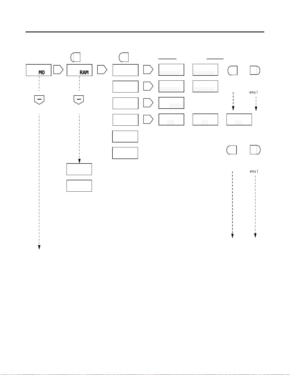
Eaton 57600-401 User manual

INSTALLATION AND OPERATION
MANUAL Number 57600-901-05
N A E D
ASSOCIATE
•Six Digit, Single Preset Counter
•1/Tau Rate Meter
•Counter and Rate Meter Scaling
•Four User-Configurable Control Inputs
•One Output Relay
•Two Solid State Outputs
•RS-485 Serial Communications
•Choice of Green or Red Display
TABLE OF CONTENTS
1 Introduction
3 Front Panel Features
4 Run Mode Operation
5 Programming
12 Scale Factors
13 Rear Terminal Description
15 Wiring Diagrams
18 Serial Communications
24 Diagnostics and Troubleshooting
26 Specifications
27 Parts and Accessories
Durant
®
AMBASSADOR SERIES COUNT CONTROL
MODELS:
57600-401 (10-15 VDC)
57601-401 (115 VAC)
57602-401 (230 VAC)
5760X-451 (Red Display)
Durant
Durant
®
EXIT ENT
HELP
RST
CLR RUN
PGM
SEL
C 123456
P1 10000

1
INTRODUCTION
MENU PROGRAMMING
AnotheruniquefeatureoftheAmbassadorfamilyofcounters
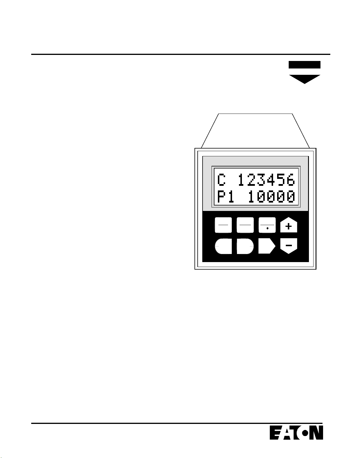
isthemenudrivenprogramming.Thetwolinealpha-numeric
display prompts programming choices, thus eliminating the
need to remember or look up programming codes. A non-
volatile memory retains programming choices, presets, and
count values while power is removed.
APPLICATION
To better understand the features and capabilities of the
Ambassador, review the simplified block diagram at the top
of the next page and the programming diagrams on pages 6
through 9. Because of the Ambassadors’s versatility, both
programmingandwiringdecisionsmustbemadebeforethe
counter can be operated. The following sequence of activi-
ties is recommended:
1. Answer the following questions:
What should the count register represent?
What should each output control or do?
What effect should the preset have on the outputs?
What should cause the count register to reset?
Which control signals should affect outputs (resets,
programmable inputs, output timers, etc.)?
What engineering units should the rate represent?
2. Gothroughtheprogrammingsectionandmarkthechoices
required for the application.
3. Go through the wiring section and lay out the wiring
required. Remember that wiring is affected by program-
ming.
4. Wire and program the counter as determined in steps 2
and 3 above.
GENERAL DESCRIPTION
The Durant Ambassador 5760X-401 is a six digit single
preset count control device with four programmable inputs,
threeoutputs,andabuilt in rate meter.Thecounterhasnine
countinputmodes, and maybeusedto controlcutlength,fill
quantity, or number of pieces/container. Each of the inputs
may be programmed for one of six functions. Each of the
outputs are independent and have separate pick-up, drop-
out, time, latch, and reverse functions.
RATE METER
In addition to count/control capabilities, a rate meter is
provided to monitor the speed of the incoming count signal.
Thisratefeatureusesthe1/taumethod(eventtimemeasure-
ment)andcancalculateandscaletheratesothatevenalow
count speed (.1 Hz) can yield accurate rates in engineering
units (ft./sec., gal/min., etc.). The rate feature operates
simultaneously with the count/control functions.
PROGRAMMABLE I/O
One of the unique features of the Ambassador family of
counters is the programmability of the inputs and outputs.
Eachofthefourinputscanbeindependentlyprogrammedto
perform one of six functions. The user can also select which
events (counter preset outputs, counter reset inputs, serial
commands, output timers, and output control inputs) will
cause each of the three outputs (1 relay and 2 transistor) to
pick-up and drop-out. Any input(s) may be programmed for
output control, however, multiple output control inputs are
paralleled into a single output control channel in the unit.
DISPLAY
AllAmbassadorCount/Controlsareavailableingreenbacklit
LCD display and reverse image red LCD display versions.

2
BLOCK DIAGRAM/OVERVIEW
COUNT SCALER
Receives the up or down signals and adds or subtracts the
scale factor value to/from the current scaler remainder. The
scaler outputs the integer result as up or down pulses. The
fractionalportionofacountremainingisstoredinthescaler’s
memory.
COUNTER
Counts the up and down pulses from the scaler. Every two
milliseconds, the counter checks if its value has passed
through the preset value (coincidence). For coincidence to
occur, the counter must count up to the preset in the reset to
zero mode and count down to zero in the reset to preset
mode. Ifcoincidencehasoccurred,themaincounteroutputs
a pulse on the preset output. The main counter counts in the
opposite direction if it is programmed to reset to preset.
PROGRAMMABLE INPUTS
The Ambassador unit has five programmable inputs (RST/
CLR key and four terminals). The user may program each
input for one of six functions (see INPUTS, page 10).
RELAY AND TRANSISTOR OUTPUT LOGIC
Theseblocksact like latchingrelays.Whenthe pick-upinput
receivesapulse,theoutputturnsonandstaysonuntilittimes
out or until the dropout input receives a pulse.
RATE METER BLOCK
TheRateMeterBlockmeasuresthetimedurationofa pulse
or group of pulses received at input A. It uses this measure-
ment along with the rate scaler to calculate the rate in
meaningful units. Internal logic resets the rate meter if the
count direction reverses.
Count
Signal
From
Sensor(s)
COUNT
SCALER COUNTER
RATE METER
(Rate Scaling)
Pick
Up
Drop
Out
Pick
Up
Drop
Out
RELAY 1
OUTPUT
LOGIC
TRANSISTO
R
2 OUTPUT
LOGIC
R1
T2
Preset
Pick
Up
Drop
Out
T1
TRANSISTO
R
1 OUTPUT
LOGIC
Inp 1
Inp 2
Inp 3
Inp 4
R/P
C
RS
T
CL
R

3
FRONT PANEL FEATURES
Two line LCD Display - Shows
count,preset,andratevalueswhen
unit is in the run mode. Displays
programminginformationwhenthe
unit is in the program mode.
RST
CL
R
EXIT
ExitKey- Inthepreseteditingmodethiskey
allowsthepreseteditingprocesstobeexited
withoutalteringthepreviouspresetvalue. In
the program mode this key exits program
changesthathavebeenselectedbutnotyet
entered.
ENT
HELP
SEL
Key Functions
Help/Key - In the run mode this key causes
the Help Screens to be displayed. In the
program mode this key is used to set the
decimal point positions for count and rate
scaler displays.
UpArrow/Plus(+)Key- Intherunmodethis
key is used to scroll up through the three
different display screens. In the preset edit-
ing mode this key adds 1 (increments) to the
value of the selected digit each time it is
pressed. In the program mode this key is
used to step vertically up through the menus
and increment the value of selected digits
when changing numeric values.
Reset/Clear Key - In the run mode this key
canbeprogrammedtoresetcountvalues. In
the preset editing mode this key zeros pre-
sets that are being changed. In the program
mode it zeros numeric data that is selected
for editing.
Enter Key - Intherunmodethiskeycauses
presetchanges totakeeffect.Intheprogram
mode it causes the displayed program
changes to be entered.
Select Key - Inrunmodethiskeyallowsthe
editingofpresetsandselectsindividualdigits
of the preset. In program mode this key is
used to move into more detailed menus and
selects the digits of numeric values needed
for programming.
Down Arrow/Minus (-) Key - In the run
mode this key is used to scroll down through
the three different display screens. In the
preset editing mode this key subtracts 1
(decrements) from the value of the selected
digit each time it is pressed. In the program
mode this key is used to step vertically down
through the menus and decrement the value
of selected digits when changing numeric
values.
RU
N
PG
M
Run/Program Key - Press this key followed
by the Enter key (ENT) to enter the program
mode.Pressingthiskey while intheprogram
mode returns the control to the run mode.
Durant
®
EXIT ENT
HELP
RST
CLR RUN
PGM
SEL
C 123456
P1 10000

4
SEL
C 123456
P 25000
RATE
600.0
C 123456
R 600.0
Count & Preset 1
1
C 123456
P 25000
1
SEL selects digit to be programmed
from left to right. +and - add 1 and
subtract 1 from the selected digit.
RUN MODE PRESET EDIT MODE
Data field flashes press
to return
one men
u
level
pres
s
to enter
data and
return on
e
menu lev
e
pres
s
to scroll
down Rate Indicator
Count and Rate
ENTEXIT
RUN MODE OPERATION
SELECTING DISPLAY INFORMATION
This Ambassador control has three available run mode
displays. Use the up and down arrow keys to select the
desired display.
Theselecteddisplaywillremainonuntiloneofthearrowkeys
is pressed to cause a change.
The screen selected for display during run-mode only pro-
vides information to the operator and does not affect the
operation of the control.
If power is removed and restored, the unit will power-up with
the display that was last selected.
RUN MODE MENUS
The keystroke sequence used to access all of the available
run mode screens and change preset values is shown in a
menu format below.
CHANGING PRESET VALUES
The preset value is set as follows:
1. Use the up and down arrow keys to select the preset
screen.
2. Press theSELkeyto enter the preset change mode. The
display will show all digits of the preset value. The left-
most digit will flash indicating that it is currently selected.
To set the preset to zero, press the RST/CLR key.
3. Use the SEL key to select the digit to be changed. Each
time the key is pressed, the next digit to the right is
selected.Thedigitvaluecanthenbechangedusingtheup
and down arrow keys.
4. Press the ENT key to enter the new preset value and
returntotherunmodescreens.PresstheEXITkeyat any
time to abort preset changes.
All count and control functions continue to operate when
preset value is being changed.
Run Mode Menu Illustration

5
PROGRAM MODE
INTRODUCTION TO MENU PROGRAMMING
The menu programming format used by the Ambassador
series eliminates the need to memorize or look up program-
ming options. Program prompting is provided on the 2 line
alphanumeric display.
The programming menus are organized in a manner much
likeanoutline.Themainmenuitemsarelocatedouttothefar
left column and each successive subdivision of these main
items is located one column further to the right.
The keystroke sequences to select all of the programmable
optionsareshownintheprogrammingchartsonpages7-10.
The seven main menus are shown below.
RU
N
PG
M
Then
ENT
To enter
program
mode
The ENT key must be pressed within five seconds,
otherwisethedisplaywillreturntothelastrunmodemenu.
ENTERING THE PROGRAM MODE
Press
Overview of Main Menus
Select count mode, reset to zero or
reset to preset and auto-recycle op-
erations.
Select the input function to be per-
formed by each to the four program-
mable inputs.
Selectnormalorreverselogic,latched
orpulsed,pick-upanddrop-outevents.
Select the unit I.D. number, baud rate,
parity, and transmission delay.
Enter count scale factor and decimal
point, rate scale factor and decimal
point.
PROGRAM
SCALERS
PROGRAM
COUNT I
N
PROGRAM
INPUTS
PROGRAM
OUT MODE
PROGRAM
SER PORT
PROGRAM
SER OUT
PROGRAM
OPTIONS
press
to scroll
down
press
to scroll
up
+
Selectthedataitemstobetransmitted
when a serial group print command
(RCD7) is received.
Select the run mode function of the
front panel RST/CLR key. Restore
factory programming.
Caution: enteringtheProgramModewillcauseall
outputs to turn off. Make sure process is stopped
before entering the Program Mode.
!

6
PROGRAMMING SCALERS AND COUNT INPUTS
See pages 10-11 for detailed description of
programming options.
CONTACT
ADD/ADD
CONTACT
C/DIR
CONTACT
ADD/SUB
C SCALER
1.00000
C DEC PT
------
R SCALER
1.0000
R DEC PT
------
SEL
PROGRAM
SCALERS SEL
SEL
SEL
SEL
C SCALER
1.00000
MAIN MENU SUB MENU EDIT MENU
C DEC PT
------
R SCALER
1.0000
R DEC PT
------
Data field flashes SEL selects digit to be programmed
from left to right. +and - add 1 and
subtract 1 from the selected digit.
SEL selects digit to be programmed
from left to right. +and - add 1 and
subtract 1 from the selected digit.
HELP/• programs decimal point.
SEL selects decimal point position.
HELP/• programs decimal point.
SEL selects decimal point position.
HELP/• programs decimal point.
Select Count Input mode using the
UP and DOWN cursors to scroll thru
this menu.
CONTACT
ADD/SUB
SEL
PROGRAM
COUNT IN SEL
RESET TO
ZERO SEL RESET TO
ZERO
RESET TO
P1 ()
AUTO CYC
DISABLED SEL AUTO CYC
DISABLED
AUTO CYC
P1 (0)
Select Reset to Zero
or
Select Reset to Preset
Select Auto Cycle Disabled
or
Select Auto Cycle on P1
PROGRAM INPUTS
press
to return
one menu
level
press to exit to
main menu
press
to scroll
down
press
to scroll
down
press
to scroll
down
press
to scroll
down
press
to enter
data and
return one
menu level
SOLID ST
QUAD x1
SOLID ST
QUAD x2
SOLID ST
Cx2/DIR
SOLID ST
Cx1/DIR
SOLID ST
ADD/ADD
SOLID ST
ADD/SUB
ENT
EXIT
EXIT

7
PROGRAMMING CONTROL INPUTS
See pages 10-11 for detailed description of
programming options.
MAIN MENU SUB MENU EDIT MENU
Data field flashes
INPUT 1
DISABLED
SEL
PROGRAM
INPUTS
SEL
Define input function from the
list provided. Repeat for
INPUT 2, INPUT 3, INPUT 4.
INPUT 1
OUT CTRL
INPUT 1
RS C EDG
INPUT 1
RS C LVL
Output Control
Reset Counter,
Edge triggered
Reset Counter,
Level sensitive
INPUT 1
LOCK ALL
INPUT 1
STOP CNT
INPUT 1
LOCK PGM
INPUT 2
DISABLED
INPUT 3
DISABLED
INPUT 4
DISABLED
Count Inhibit
Lock Program
mode.
Lock Program &
Preset edit mode
Repeated as above for INPUT 1.
PROGRAM
OUTPUTS
press
to return
one menu
level
press
to enter
data and
return one
menu level
press to exit to
main menu
press
to scroll
down
press
to scroll
down
ENT
EXIT
INPUT 1
DISABLED
EXIT

8
See pages 10-11 for detailed description of
programming options.
PROGRAMMING OUTPUTSPROGRAMMING CONTROL INPUTS
Data field flashes
RELAY 1
PROGRAM
SEL
PROGRAM
OUT MODE
SEL
RELAY 1
NORMAL
RELAY 1
LATCHED
RELAY
PUL 1.00
RELAY 1
P1 NA
SEL
RELAY 1
NORMAL
RELAY 1
LATCHED
RELAY
PUL 1.00
RELAY 1
P1 NA
or
or
or
RELAY 1
REVERSE
RELAY 1
PULSED
RELAY 1
P1 PU or
No Action Pick Up output
RELAY 1
P1 D0
Drop Out output
Enter output pulse time
XX . XX seconds
SEL
SEL
SEL
MAIN MENU SUB MENU VIEW MENU EDIT MENU
PROGRAM
SERIAL
PORT
Preset 1
press
to return
one menu
level
press
to enter
data and
return one
menu level
press to exit to
sub menu
press
to scroll
down
press to exit to
main menu
press
to return
one menu
level
press
to enter
data and
return one
menu level
press
to scroll
down
ENT
ENT
EXIT
EXIT
EXIT
EXIT
RELAY 1
OCTRL NA
RELAY 1
RS C NA
Selection repeats as
for P1 above
Selection repeats as
for P1 above
TRANS 1
PROGRAM
TRANS 2
PROGRAM
Repeats as for RELAY 1 above.
Output
Control In
Front panel
and Remote
Counter Rst

9
PROGRAMMING SERIAL PORT AND OPTIONS
See pages 10-11 for detailed description of
programming options.
Data field flashes
MAIN MENU SUB MENU EDIT MENU
SER PORT
ID 00
BAUD
4800
PARITY
NONE
Tx DELAY
0.002
SEL
PROGRAM
SER PORT SER PORT
ID 00
BAUD
4800
PARITY
NONE
Tx DELAY
0.002
SEL
Program two digit serial port address.
(Must be in a range from 00-99)
Select 4800, 2400, 1200 or 300 BAUD.
Select Parity bit as NONE, ODD or EVEN.
Select either 0.002 sec or 0.100 sec Transmit
Delay.
SEL
SEL
SEL
SEL
PROGRAM
SER OUT COUNT
SKIP SEL COUNT
SKIP
Select SKIP or SEND for each data block to be
transmitted when requested by the host
computer.
press
to return
one menu
level
press to exit to
main menu
press
to scroll
down
RATE
SKIP
P1
SKIP
RATE
SKIP
P1
SKIP
SEL
SEL
press
to scroll
down
press
to scroll
down
PROGRAM
OPTIONS RST KEY
DISABLED
SEL SEL RST KEY
DISABLED
RST KEY
RS C EDG
RST KEY
RS C LVL
Define the function of the front panel RST/CLR
key.
Reset Counter, Edge triggered
Reset Counter, Level sensitive
USER
PROGRAM USER
PROGRAM DEFAULT
PROGRAM
SEL
or Load DEFAULT forces
the control to the factory
programmed state.
press
to scroll
down
press
to scroll
down
roll around to
PROGRAM
SCALERS
press
to enter
data and
return one
menu level
ENTEXIT
EXIT

10
DESCRIPTION OF PROGRAM OPTIONS
SCALERS
CSCALER—thecountscalerdeterminesthevalue of each
input pulse. The counter displays whole numbers only. The
count scale factor affects the counter but does not affect the
ratemeter.Thecountscaler’sdecimalpointpositionisfixed.
C DEC PT — sets the decimal point position for the counter.
The decimal point position and scale factor value are inde-
pendent.
RSCALER—theratescaleris used to adjust the ratemeter
reading and compensate for the number of input pulses per
item. The rate scaler's decimal point is programmable. The
rate scaler and count scaler are independent.
R DEC PT — sets the decimal point position for the rate
display. The rate decimal point position and scale factor
value are independent.
COUNT INput
CONTACT ADD/SUB — input A adds counts and input B
subtracts counts. This mode includes input filtering to
debounce mechanical contacts.
CONTACT ADD/ADD — inputs A and B both add counts.
This mode includes input filtering to debounce mechanical
contacts.
CONTACT C/DIR — count with direction control. Input A
adds counts when the B input is high. Input A subtracts
counts when the B input is low.
SOLID ST QUAD x1 — requires a quadrature signal input.
Thismodeprovidesdirectioncontrolandisusedtoeliminate
false counts due to jitter or vibration. The count direction
depends on the phase relationship of inputs A and B.
SOLID ST QUAD x2 — same as the quadrature x1 mode
aboveexceptthatcountsoccuronbothedgesofinputsignal.
Thisallowsincreasedresolutionfromthesamepulsesource.
SOLID ST ADD/SUB — same as the contact add/subtract
mode but can be used with high speed count signals.
SOLID ST ADD/ADD — same as the contact add/add mode
but can be used with high speed count signals.
SOLID ST C x1/DIR — same as contact count/direction but
can be used with high speed count signals.
SOLID ST C x2/DIR — same as above except counts occur
on both edges of input signal for increased resolution.
RESET TO ZERO — the counter resets to zero when a
counter reset occurs. The normal count direction is up and
the counter outputs respond only when counting up.
RESET TO P1 ( ) — the counter resets to the preset value
when a counter reset occurs. Preset coincidence occurs
when the counter reaches zero. The normal count direction
is down and the counter preset output responds only when
counting down.
AUTO CYC DISABLED — the counter does not automati-
cally reset when it reaches the preset value.
AUTO CYC P1(0) — the counter automatically resets as
programmed when it reaches the preset coincidence value.
The preset coincidence value is zero when in the reset to
preset mode.
INPUTS
INPUT1DISABLED—input1doesnotperformanyfunction
when turned on.
INPUT 1 OUT CTRL — when input 1 is turned on, an output
control signal occurs (edge sensitive). While more than one
inputmaybeprogrammedforoutputcontrol,onlyoneoutput
control channel is available in the unit.
INPUT 1 RS C EDG — the counter resets when input 1 is
turnedon(edgesensitive).Ifinput1remainson, the counter
can still count.
INPUT 1 RS C LVL — the counter is held at the reset value
while input 1 is on (level sensitive).
INPUT 1 STOP CNT — all count functions stop (inhibited)
while input 1 is on (level sensitive).
INPUT 1 LOCK PGM — all program editing is disabled
(keyboard and serial) while input 1 is on (level sensitive).
Preset values can still be changed serially or from the
keyboard.
INPUT 1 LOCK ALL — all programming and preset editing
functions (keyboard and serial) are disabled while input 1 is
on (level sensitive). The user can still select different run
mode displays from the keyboard.
Eachoftheabovefunctions are repeated forinputs2,3,and
4 respectively.

11
DESCRIPTION OF PROGRAM OPTIONS
OUTput MODE
RELAY 1 NORMAL — relay 1 turns on when it receives a
pick-up signal and turns off when it receives a drop-out
signal.
RELAY 1 REVERSE — relay 1 turns on when it receives a
drop-out signal and turns off when it receives a pick-up
signal. The relay always powers-up in the off state.
RELAY1LATCHED—relay1turnson(offifreversed)when
itreceivesapick-upsignalandstayson(offifreversed)until
it receives a drop-out signal.
RELAY 1 PULSED — relay 1 turns on (off if reversed) when
it receives a pick-up signal and automatically turns off (on if
reversed) after the time specified below.
RELAY1PUL — enter the desired time for relay 1 to stay on
(00.01to99.99seconds).Thisscreenisnotdisplayedunless
pulsed is selected in the menu above.
RELAY 1 P1 — relay 1 can be programmed for no action,
pick-up or drop-out when the main counter reaches the
preset.
RELAY 1 OCTRL — relay 1 can be programmed for no
action, pick-up or drop-out when an output control signal
occurs. One of the inputs must be programmed for output
control before a RELAY 1 OCTRL can occur.
RELAY 1 RS C — relay 1 can be programmed for no action,
pick-up or drop-out when a reset counter signal occurs. The
reset key or one of the inputs must be programmed to reset
the main counter before a RELAY 1 RS C can occur.
Eachofthesefunctionsisrepeatedfortransistoroutput1and
transistor output 2 sub-menus.
SERial PORT
SERPORTID—enterthedesiredtwodigitserialIDnumber
(00-99 decimal). All communications to the control must
containthisnumber(inhexadecimal).Eachunitmusthavea
unique ID#.
BAUD — selects the serial port transmit and receive baud
rate. Allowable rates are 19200*, 9600*, 4800, 2400, 1200,
and 300.
*Version 5 firmware or later. To check firmware version,
pressHelpkeytwicefrom run mode. Firsttwodigits(topleft)
should read "25" or greater for version 5 or later.
PARITY — the user may select none, odd, or even parity. If
none (no parity) is selected, the counter transmits space
parity and does not check received parity.
Tx DELAY — The user may select a transmission delay of
either 2 or 100 milliseconds. The counter waits for this time
periodbeforerespondingtoanyserialcommands.Thisdelay
is provided to allow a host computer time to switch from the
transmit to receive mode.
SERial OUT
These options determine which items are sent when the
counter receives the RCD7 command.
OPTIONS
RSTKEYDISABLED—theRST/CLRkey does not perform
any function.
RST KEY RS C EDG — the counter resets when the RST/
KEY is pressed (edge sensitive). If the RST/KEY is held on,
the counter can still count.
RST KEY RS C LVL — the counter is held at the reset value
while the RST/KEY is pressed (level sensitive).
USER/DEFAULT PROGRAM — If the user selects default,
the counter returns all program mode options to the factory
setvalues(firstchoiceshowninmenus).Counterandpreset
values are not affected. This screen shows USER PRO-
GRAM if any options have been changed from the default
settings.

12
CALCULATING SCALE FACTORS
RATE SCALING
The 1/Tau rate meter calculates rate by measuring the time
interval between input pulses, converting to frequency, and
multiplying by the rate scaler. The rate scaler is user pro-
grammedtoconvertthecount input pulse frequency into the
desiredunitsfordisplay(feet/minute,inches/second, boxes/
hour, etc.).
Rate Scaler Range: 0.00001 to 99999
Default Rate Scaler: 1.0000
Rate Scaler (RS) formula:
SEC x DPF
RS =
PPI
where:
SEC is the number of seconds in the rate time unit (items/
minute = 60, items/hour = 3600, etc.).
DPF is the decimal point factor determined by the desired
decimal point position on the rate meter display:
DISPLAY DPF DISPLAY DPF
XXXXXX = 1 XXX.XXX = 1,000
XXXXX.X = 10 XX.XXXX = 10,000
XXXX.XX = 100 X.XXXXX = 100,000
(Use the rate decimal point menu to select the desired
decimal point position for the rate meter.)
PPI is the number of pulses per item from the sensor (times
2 if doubled count mode).
Example 1: A sensor produces 1 pulse per foot of material
travel. Display rate in whole feet per minute (XXXXX).
60 x 1
RS = = 60.000
1
Example 2: A flow sensor produces 400 pulses per gallon.
Display flow rate in tenths of a gallon per minute (XXXX.X).
60 x 10
RS = = 1.5000
400
(Select the XXXXX.X position on the rate decimal point
menu.)
COUNT SCALING
The count scaler is a user programmable number which
determines the count value of each input pulse. It is used to
correct for a known amount of error (wheel wear, viscosity,
etc.) or to convert the incoming count signal into the desired
units of measure on the display (feet, gallons, yards, etc.).
The main counter and totalizer show whole (integer) counts;
the scaler retains fractional counts.
Count Scaler Range: 0.00001 to 9.99999
Default Count Scaler: 1.00000
Count Scaler (CS) Formula:
DPF
CS =
PPI
where:
DPF is the decimal point factor determined by the desired
decimal point position on the main counter and totalizer
display:
DISPLAY DPF DISPLAY DPF
XXXXXX = 1 XXX.XXX = 1,000
XXXXX.X = 10 XX.XXXX = 10,000
XXXX.XX = 100 X.XXXXX = 100,000
(Use the counter decimal point menu to select the desired
decimal point position for the main counter and totalizer.)
PPI is the number of pulses per item from the sensor (times
2 if doubled count mode).
Example1: Asensorproduces20pulsesperinchofmaterial
travel. Calculate the count scaler required to indicate mate-
rial used in whole inches (XXXXXX).
1
CS = = 0.05000
20
Example 2: An encoder produces 120 pulses per foot.
Calculate the count scaler required to indicate material
usage in 1/100’s of feet (XXXX.XX).
100
CS = = 0.83333
120
(Select the XXXX.XX position on the counter decimal point
menu).

13
+12 Volt DC
DC Common
DC Common
Ground
No Connection
No Connection
No Connection
Relay 1 N.C.
Relay 1 Com.
Relay 1 N.O.
AC Power Neut
AC Power Hot
Transistor 2 Output
Transistor 1 Output
Input 1
Input 2
Input 3
Input 4
Count Input B
Count Input A
Communication +
Communication -
RS-485 communication con-
nector, RJ-11 modular tele-
phone style.
1
12
2
3
4
5
6
7
8
9
10
11
13
14
15
16
17
18
19
20
21
22
4
3
2
1
TERMINAL DESCRIPTIONS
1-Onmodels57601and57602thisterminal isthe+12 VDC
power output. It is used to supply 12 VDC (+/- 25% 100 mA
max)foraccessories.DCCommonisthenegativesideofthis
supply.
On the model 57600 this terminal is used for the 10-15 VDC
powerinput.Connectthepositiveleadofthepowersupplyto
terminal 1 and the negative lead to DC Common.
The DC POWER OUTPUT contains a series Positive Tem-
perature Coefficient (PTC) resistor that undergoes a large
and abrupt increase in resistance when an over-current
condition occurs. This resistance change limits the fault
currenttoseveralmilliamps. ThePTCdevicewillreset when
theunit power has been removed for atime sufficient to cool
the device. The overload condition should be removed be-
fore unit power is reapplied.
2, 3 and 4 -DCCommon: Theseterminalsareconnectedto
the negative side of the counter’s internal DC power supply.
Count inputs must be referenced to DC Common. Control
inputs are on when connected to DC Common. Transistor
outputs conduct to DC Common when picked up. For maxi-
mumnoiseimmunity,thegroundterminalmustbeconnected
to a good earth ground. All shielded signal cables should be
connected to earth ground or ground on the counter.
5, 6 and 7 - Not used
8, 9 and 10 - Relay 1 contacts: The relay output consists of
oneelectricallyisolatedformCsetofcontacts.Theusermust
supply power through a contact to the external load. The
contacts remain in the normal state until a pick-up signal
occurs. The relay remains picked up (on) until a drop out
signaloccurs(see output programming diagrampage8and
block diagram page 2).
11 and 12 - AC Power Inputs:
Model 57601-401 115VAC
Model 57602-401 230VAC
Model 57600-401 Not used
13, 14 - Transistor Outputs 2 and 1: These terminals are
separateopencollectorNPNtransistor outputs.Eachoutput
conducts to DC Common when picked up (see output pro-
gramming diagram page 8 and block diagram page 2).
15, 16, 17, and 18 - Inputs 1, 2, 3, and 4: Programmable
inputs. The user can assign one of six functions to each
individual input. The inputs require a current sinking signal
(contact or solid state) to DC Common (see input program-
ming diagram page 7 and block diagram page 2).
19, 20 - Count Inputs B and A: Connect the count input
signal(s)totheseterminals.Thecount inputcanoperatewith
either a current sinking signal (contact or solid state) to DC
Common or a current sourcing signal. (See specifications,
programming diagram page 6, and block diagram page 2.)
Rate calculations are made from count pulses into Input A
only.
21, 22 - RS-485 serial I/O port: Connect terminal 21 to the
positive lead of the communications bus. Connect terminal
22 to the negative lead of the communications bus.
REAR TERMINAL DESCRIPTION

14
Switch 2: Input B sink/source
Off: input B requires a current sinking input signal.
On: input B requires a current sourcing input signal.
Switch 3: Input A threshold level
Off: high threshold level — use with DC sensors.
On: low threshold level — use with mag pickups. Turn
switch 1 on.
Switch 4: Input B threshold level
Off: high threshold level — use with dc sensors.
On: low threshold level — use with mag pickups. Turn
switch 2 on.
Dip switches may be set through an opening on the bottom
of the unit. It is located towards the rear of the control.
PANEL MOUNTING
The panel mounting kit includes:
(1) mounting gasket, (2) mounting clips and (4) screws.
Refer to the dimension diagram on page 28 for a drawing of
the correct installation of these parts.
The mounting gasket is coated on one side with a contact
adhesive and a paper backing. Care should be taken during
thegasketinstallationthatthegasketbecorrectlypositioned
onthepanel atthefirstattempt.Attemptingtore-position the
gasketoncetheadhesivehascomeincontactwiththepanel
is likely to deform or tear the gasket. This may result in an
improper seal. For best results, follow these directions:
1. StandtheAmbassador counteronadeskortablewith its
display down, screw terminals up.
2. Remove and discard the center square of the gasket at
thescribemarksin the gasketandpaperbacking.Do not
remove the backing from the remaining outer rim.
3. Slide the gasket down the unit until it is in position at the
rear of the unit's front bezel. The paper backing side
should be up.
4. Insertthe tip of a knife between thepaper and the gasket
and, while holding the gasket down to the unit with the
knife, peel off the paper backing.
5. Slide the unit through the panel cutout until the gasket
firmly adheres to the panel.
6. Install the mounting clips and screws as shown in the
diagram on page 28. Do not overtighten the mounting
screws.Thescrews should be tight enough to firmly hold
theunitin place,butnotsotightasto squeezethegasket
out from behind the front bezel.
7. A switch shall be included in the building installation:
•It shall be in close proximity to the equipment and
within easy reach of the operator.
•It shall be marked as the disconnecting device for the
equipment.
•Switches and circuit breakers in Europe must comply
with IEC 947.
REAR TERMINAL DESCRIPTION CONTINUED
!
MODULAR COMMUNICATION JACK
ThemodularphonejackisanalternateconnectiontotheRS-
485 communications port. Pin 2 is positive and is the same
as terminal 21. Pin 3 is negative and is the same as terminal
22. Pins 1 and 4 are connected to DC Common and should
be used for any shield connections.
Note: This jack is intended only for connection to Ambassa-
dor and other RS-485 communication networks. It
should not be connected to any telephone sys-
tem - damage or hazard may result.
TERMINAL BLOCKS
Connections to the Ambassador are made through deplug-
able, screw terminal blocks to allow for ease of wiring and
removal of the counter. The terminals can accommodate
stranded,solidorfusedwire(preferred)from14to22gauge.
To remove the terminal block, remove AC power and pry
gently underneath each end of the terminal block with small
screwdriver. Press straight on to re-install.
GENERAL WIRING PRACTICES
1. Disconnect all power before wiring terminals. A safety
hazard exists if this precaution is not observed.
Treat all control and count inputs as hazardous
since they may carry line voltage.
2. Use shielded cables for count signals, control input and
communicationssignals.Connectshieldtocommon(ter-
minal 2, 3 or 4) of counter to terminate properly.
3. Keep all signal lines as short as possible.
4. Do NOT bundle or route signal lines with power or
machine control wiring. Use separate conduit for power
and signal wires.
5. Provide "clean" power to the counter. In severe cases,
powermayhavetobefilteredoraseparatepowersource
used.Donotusethesamepowersourcethatissupplying
the loads.
6. Use 18 ga. minimum (0.97mm2, 600V) and 14 ga.
maximum (2.1mm2, 600V) wire for AC power wiring.
7. Seepage15,topdrawing,forthecorrectfusetobeused
in the power input wiring.
DIP SWITCH FUNCTIONS
Switch 1: Input A sink/source
Off: input A requires a current sinking input signal.
On: input A requires a current sourcing input signal.

15
AC WIRING/CONTACT INPUT WIRING
AC Power Input
(AC Models Only)
N
eutra
l
H
ot
AC
P
ower
I
n
El
ectr
i
ca
l
Ground
Terminal 4 (Ground) and terminals
2 and 3 (Com) are internally
connected.
Terminal 4 (Ground) and terminals
2 and 3 (Com) are internally
connected.
10-15
VDC
I
nput +
DC Power Input
(DC Models Only)
Check part number on counter
label to verify correct voltage
rating.
57601-40X: 115 VAC
57602-40X: 230 VAC
Check part number on counter
label to verify correct voltage
rating.
57600-40X: 10-15 VDC
1
12
2
3
4
5
6
7
8
9
10
11
13
14
15
16
17
18
19
20
21
22
1
12
2
3
4
5
6
7
8
9
10
11
13
14
15
16
17
18
19
20
21
22
To prevent multiple counts, use one
of the contact count modes. See
programming diagram.
All dip switches OFF.
P
us
h
b
utton
limit switch,
relay contact,
etc.
Contact Count Input
1
12
2
3
4
5
6
7
8
9
10
11
13
14
15
16
17
18
19
20
21
22
D
otte
d
li
nes
i
n
di
cate w
hi
c
h
inputs may be wired in this
manner. Typically a separate
sensor is used for each input.
Control inputs (terminals
15-18) may be wired in the
same manner.
-
Use slow blow fuses for all voltages.
Use 1/2 amp slow blow fuse.
(Does not include external
transducer load.)
Fuse Size
AC Power In
115 V, 60 Hz
115 V, 50 Hz
230 V, 60 Hz
230 V, 50 Hz
U.S.
1/8 amp
1/4 amp
1/16 amp
1/8 amp
European
T125 mA, 250 V
T250 mA, 250 V
T 60 mA, 250 V
T125 mA, 250 V

16
COUNT INPUT WIRING
Do not connect Term 1 if sensor is
powered from another power
supply.
Wire colors shown correspond to
Cutler-Hammer inductive proximity
and photo sensors.
All dip switches OFF.
Current Sinking Sensor
Count Input
C
urrent s
i
n
ki
ng
(
open
collector NPN transistor)
sensor output
Bl
ac
k
+12
VDC
B
rown
DC
C
om
Bl
ue
C
ount
Signal
AC Signal Count Input
17 VAC RMS 48 V Peak-to-Peak
maximum into 2.3 KΩload
impedance. Use an external
resistor (R) in series with the count
input signal for input voltages (V)
greater than 17 VAC.
R = (V x 230) - 2300
Dip switches 3 and/or 4 ON (AC
mode).
Dip switches 1 and 2 ON.
1
12
2
3
4
5
6
7
8
9
10
11
13
14
15
16
17
18
19
20
21
22
1
12
2
3
4
5
6
7
8
9
10
11
13
14
15
16
17
18
19
20
21
22
DC
C
om
D
otte
d
li
nes
i
n
di
cate w
hi
c
h
inputs may be wired in this
manner. Typically a separate
sensor is used for each input.
Control inputs (terminals
15-18) may be wired in the
same manner.
Do not connect Term 1 if sensor is
powered from another power
supply.
Wire colors shown correspond to
Cutler-Hammer inductive proximity
and photo sensors.
Dip switches 1 and/or 2 ON to
select current source mode,
switches 3 and 4 OFF.
Current Sourcing Sensor
Count Input
C
urrent sourc
i
ng
sensor output
Th
e output vo
l
tage o
f
t
hi
s
sensor must be between
3.5 and 17 VDC (100%
duty cycle) into a 2300Ω
load. Use an external
resistor (R) in series with
the count signal for
voltages (V) greater than
17 VDC.
R = (V x 230) - 2300
Bl
ac
k
+12
VDC
B
rown
DC
C
om
Bl
ue
C
ount
Signal
1
12
2
3
4
5
6
7
8
9
10
11
13
14
15
16
17
18
19
20
21
22
Caution:
The unit requires 1.2 V P-to-P
minimum signal amplitude to
count. Magnetic pickups produce
an output voltage directly
proportional to the speed of the
ferrous material passing the
pickup. At low speeds, or at
starting or stopping, the output
voltage from the pickup may not
be great enough to cause the
counter to count. For magnetic
pickup signals in the range of 50
mV to 400 V P-to-P, a signal
conditioner (Durant part no.
48160-400) is recommended.

17
ENCODER WIRING/OUTPUT WIRING
Relay Contact Output Wiring
Shaft Encoder Wiring
XXX
=
N
um
b
er o
f
pu
l
ses per revo
l
ut
i
on
60,100, 120, 600 Standard
Y
e
ll
ow
+12
VDC
R
e
d
DC
C
om
Bl
ac
k
(Encoder Pin D)
Sh
a
f
t
E
nco
d
er
Durant Pt #
3815
X
-
XXX
or
4837X-XXX
Bl
ue
(Encoder Pin E)
(E
nco
d
er
Pi
n
A)
(E
nco
d
er
Pi
n
B)
1
12
2
3
4
5
6
7
8
9
10
11
13
14
15
16
17
18
19
20
21
22
1
12
2
3
4
5
6
7
8
9
10
11
13
14
15
16
17
18
19
20
21
22
Do not connect Term 1 if sensor is
powered from another power
supply.
Wire colors shown are for
quadrature encoder, do not connect
the yellow wire for a single channel
encoder.
All dip switches OFF.
This wiring example shows the load
being controlled from the normally
open contacts of Relay 1. Wiring for
the normally closed contacts (8,9)
would be done in the same manner.
Wiring for the Relay 2 contacts
(5,6,7) is also done in the same
manner.
L
oa
d
AC
or
DC
P
ower
Source for Load (275
VAC, 150 VDC Max.)
Wiring DC Loads to
Transistor Outputs 1
12
2
3
4
5
6
7
8
9
10
11
13
14
15
16
17
18
19
20
21
22
The load must not draw more than
200 mA of current.
The counter's internal DC supply
can be used to power DC loads.
The total current drawn from
terminal 1 cannot exceed 100 mA.
Use external diode suppression in
parallel with inductive loads.
1
+
L
oa
d
s
DC
P
ower
f
or
L
oa
d
30 VDC, 200 mA
maximum.
+
2
3
1
2
3
3

18
INTRODUCTION TO SERIAL COMMUNICATIONS
Theadvancedcommunicationcapabilityofthe Ambassador
controlallowsahostcomputertoreadandresetthe counter,
read and write the preset, inhibit and enable counts, turn
outputs on and off, lock and unlock the keyboard, and read
and program all setup parameters.
The Control uses ASCII code with the RS-485 serial specifi-
cation and Opto-22 compatible protocol. This allows bi-
directional communications and addressing of multiple con-
trols on a single two-wire communication bus. Each unit is
individually addressed via a user programmable ID number.
Up to 100 counters can be connected directly to the bus.
Interconnect kits and bulk RS-485 communication cable are
available; see accessory parts list.
Serial Command Summary
ESP: Enter Serial STP: Stop Count
programming WP1: Write Preset 1
LAL: Lock All WPI: Write Program
LPG: Lock Program Item
OCL: Output Control UAL: Unlock All
RCD: Read Counter Data UPG: Unlock Program
RDV: Read Device Value XSP: Exit Serial Pro-
RPI: Read Program Item gramming
RSC: Reset Counter
Example Ambassador Serial Communication Network
SERIAL COMMAND FORMAT
The general command format is shown below. Spaces are
used for clarity only and must not be transmitted.
> ID# COMMAND [numeric data] CHECKSUM (cr)
Example:
To cause unit# 10 to transmit the value of the counter, send
the RCD command as follows:
1. Message start character (ASCII 62). Required for all
transmissions to the control.
2. Two digit serial port ID# in hexadecimal. Required for all
transmissions to the control. Unit ID# 10 (decimal) is unit
ID# 0A (hexadecimal). Capital letters must be used.
3. RCD (Read Counter Data) command. All serial com-
mandsconsistofthreecharacters. Lettersmaybeupper
or lower case. (See pages 19 - 21 for description of all
commands.)
NO. 00 NO. 01 NO. 02 NO. 31
NO. 32
NO. 33NO. 34
NO. 63
NO. 64 NO. 64 NO. 65 NO. 99
RS-485 TO
RS-232
CONVERTER
HOST COMPUTER
> 0A RCD 2 7C (CR)
1 2 3 4 5 6

19
SERIAL COMMAND/RESPONSE FORMAT
4. NumericdatarequiredwiththeRCDcommandtospecify
counterorpresetto beread.Uptoeight numericcharac-
ters are required for some commands. Most commands
do not require any numeric characters (see pages 19
through 21 for list of all commands).
5. Two digit hexadecimal checksum of the ASCII values of
the ID number, command, and any required numeric
characters. Required for all transmissions to the control.
Checksum Calculation:
Thechecksumisthelasttwohexadecimalcharacters—
7A. Upper or lower case letters may be used. The > start
characterandcarriagereturnarenotusedincalculation.
6. ASCII carriage return (13 decimal). Required at the end
of all commands.
SERIAL RESPONSE FORMAT
The counter does not respond to a command unless the
transmittedIDnumbermatchesitsprogrammedID number.
If the ID numbers match and the command and checksum
are valid, the control executes the command and transmits
a response as shown below:
A [data] [checksum] (cr) where:
A is the acknowledge character (ASCII 65) sent when any
valid command is received and executed.
[data] is sent in response to the RCD, RDV, or RPI com-
mands which request data. Data is not transmitted for
other commands.
[checksum] issentonlywhen dataisrequested(RCD,RDV
or RPI commands). The checksum is calculated by
adding the ASCII values of all preceding characters
(includingthespaces,butnotincludingtheacknowledge
character "A"). The checksum is the two least significant
digits of this sum in hexadecimal.
(cr)istheASCIIcarriage return (13 decimal).Transmittedat
the end of all responses.
EXAMPLES:
A(cr) No data requested
ACT 337914 52(cr) Count data requested
If the ID numbers match but the command is not valid or
cannot be executed, the counter ignores the command and
responds by sending an ASCII “N” (not acknowledged)
followedbyaonecharactererrorcodeandacarriagereturn.
Error Codes:
00 - PowerupError—Whenpowerisappliedtotheunit,or
the program mode is exited, the unit performs a pwoer
up self test. The first valid command received by the
unit following the self test is not executed and not
acknowledged.
10 - Lock input is on — cannot change preset values or
enter serial program mode until lock input is removed.
02 - Checksumerror—receivedchecksumdoesnotmatch
calculated checksum.
01 - Command not found in table or invalid command —
WPI, RPI, XSP received when not in serial program
mode.
05 - Invalid data — incorrect number of digits or illegal
character received in data field.
11 - Preset edit in progress on keyboard — serial preset
cannot be sent if preset is being changed on the
keyboard.
12 - Command is valid for this family but not this counter or
commandisnotvalidwiththisprogramconfiguration—
cannot change output time if output is set to latch.
13 - Keyboardprogrammingmodeisactive—cannotenter
serial program mode if in keyboard program mode.
EXAMPLES: N05(cr) Invalid data
N10(cr) Lock input is on
SERIAL RUN-MODE COMMANDS
RCD(n) — Read Counter Data
Thiscommandmust befollowedbya number(n)from0to7.
Thenumberdetermineswhichvaluethecountersends. The
requested value is preceded by a two character counter or
presetabbreviation. Thecounterformatsitsresponseina12
characterfield. Thecountersendsanyprogrammeddecimal
points in the correct location. Leading zeros are sent as
spaces.
EXAMPLE COMMAND: >1BRCD37F(cr) Reads rate indi-
cator from unit 27.
EXAMPLE RESPONSES:
(n) Value Sent Response Formats with Different
Decimal Points
0 Counter ACT 123456 4C(cr)
3 Rate ART 123456 5B(cr)
4 Preset 1 AP1 123456 36(cr)
0 Counter ACT 123.456 5A (cr)
3 Rate ART 123.456 69 (cr)
4 Preset 1 AP1 123.456 44 (cr)
0 A R C D 2
48 + 65 + 82 + 67 + 68 + 50 = 380 (dec.)
This manual suits for next models
3
Table of contents
Other Eaton Cash Counter manuals

Eaton
Eaton E5524E0402 User manual

Eaton
Eaton Durant Courier Series User manual

Eaton
Eaton E5-148-C1400 User manual

Eaton
Eaton Durant AMBASSADOR Series User manual

Eaton
Eaton MN05401014E User manual

Eaton
Eaton Durant Ambassador 57600-400 User manual

Eaton
Eaton Durant AMBASSADOR Series User manual

Eaton
Eaton E5-648-C446 Series Manual

Eaton
Eaton E5-648-C242 Series Manual

Eaton
Eaton xComfort CIZE-02/01 User manual