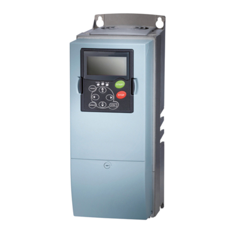
9000X AF Drives User Manual
MN04001004E
For more information visit:
www.eaton.com
iii
June 2009
List of Figures
Figure 2-1: Mounting Space Requirements. . . . . . . . . . . . . . . . . . . . . . . . . . . . . . . . . . . . . 2-1
Figure 3-1: Input Power and Motor Cable Stripping and Wire Lengths . . . . . . . . . . . . . . 3-8
Figure 3-2: Wiring Plate . . . . . . . . . . . . . . . . . . . . . . . . . . . . . . . . . . . . . . . . . . . . . . . . . . . . 3-9
Figure 3-3: Ground Terminal Locations . . . . . . . . . . . . . . . . . . . . . . . . . . . . . . . . . . . . . . . . 3-10
Figure 3-4: Cable Protection Plate . . . . . . . . . . . . . . . . . . . . . . . . . . . . . . . . . . . . . . . . . . . . 3-10
Figure 3-5: Principle Wiring Diagram of SVX9000/SPX9000 Power Unit,
FR4 to FR5 and FR6 . . . . . . . . . . . . . . . . . . . . . . . . . . . . . . . . . . . . . . . . . . . . . . . . . . . . . 3-11
Figure 3-6: Principle Wiring Diagram of SVX9000/SPX9000 Power Unit,
FR6, FR7 and FR8 . . . . . . . . . . . . . . . . . . . . . . . . . . . . . . . . . . . . . . . . . . . . . . . . . . . . . . 3-12
Figure 3-7: Principle Wiring Diagram of SVX9000/SPX9000 Power Unit,
FR9 to FR10 . . . . . . . . . . . . . . . . . . . . . . . . . . . . . . . . . . . . . . . . . . . . . . . . . . . . . . . . . . . 3-13
Figure 3-8: FR4 Power and Motor Wiring Terminals . . . . . . . . . . . . . . . . . . . . . . . . . . . . . 3-14
Figure 3-9: FR5 Power and Motor Wiring Terminals . . . . . . . . . . . . . . . . . . . . . . . . . . . . . 3-15
Figure 3-10: FR6 Power and Motor Wiring Terminals . . . . . . . . . . . . . . . . . . . . . . . . . . . . 3-16
Figure 3-11: FR7 Power and Motor Wiring Terminals . . . . . . . . . . . . . . . . . . . . . . . . . . . . 3-17
Figure 3-12: FR8 Power and Motor Wiring Terminals . . . . . . . . . . . . . . . . . . . . . . . . . . . . 3-18
Figure 3-13: FR9 Power and Motor Wiring Terminals . . . . . . . . . . . . . . . . . . . . . . . . . . . . 3-19
Figure 4-1: Option Board Slots . . . . . . . . . . . . . . . . . . . . . . . . . . . . . . . . . . . . . . . . . . . . . . . 4-1
Figure 4-2: Option Board A9 Wiring Diagram . . . . . . . . . . . . . . . . . . . . . . . . . . . . . . . . . . . 4-3
Figure 4-3: Option Board A9 Jumper Location and Settings . . . . . . . . . . . . . . . . . . . . . . 4-5
Figure 4-4: Option Board A2 Wiring Diagram . . . . . . . . . . . . . . . . . . . . . . . . . . . . . . . . . . . 4-5
Figure 4-5: Option Board A2 Terminal Locations . . . . . . . . . . . . . . . . . . . . . . . . . . . . . . . . 4-6
Figure 4-6: Positive/Negative Logic . . . . . . . . . . . . . . . . . . . . . . . . . . . . . . . . . . . . . . . . . . . 4-6
Figure 5-1: Keypad and Display . . . . . . . . . . . . . . . . . . . . . . . . . . . . . . . . . . . . . . . . . . . . . . 5-1
Figure 5-2: Main Menu Navigation . . . . . . . . . . . . . . . . . . . . . . . . . . . . . . . . . . . . . . . . . . . 5-4
Figure 5-3: Parameter Menu Structure Example . . . . . . . . . . . . . . . . . . . . . . . . . . . . . . . . 5-5
Figure 5-4: Keypad Control Menu . . . . . . . . . . . . . . . . . . . . . . . . . . . . . . . . . . . . . . . . . . . . 5-6
Figure 5-5: Active Fault Display Example . . . . . . . . . . . . . . . . . . . . . . . . . . . . . . . . . . . . . . 5-7
Figure 5-6: Sample Fault History Display . . . . . . . . . . . . . . . . . . . . . . . . . . . . . . . . . . . . . . 5-9
Figure 5-7: System Menu Structure . . . . . . . . . . . . . . . . . . . . . . . . . . . . . . . . . . . . . . . . . . . 5-10
Figure 5-8: Expander Board Menu Structure . . . . . . . . . . . . . . . . . . . . . . . . . . . . . . . . . . . 5-18
Figure 5-9: Digital Inputs — DIN1, DIN2, DIN3 Status . . . . . . . . . . . . . . . . . . . . . . . . . . . . 5-19
Figure 5-10: Digital Inputs — DIN4, DIN5, DIN6 Status . . . . . . . . . . . . . . . . . . . . . . . . . . . 5-19
Figure 5-11: Digital and Relay Outputs — DO1, RO1, RO2 Status . . . . . . . . . . . . . . . . . . 5-19
Figure 5-12: Operate Menu Navigation . . . . . . . . . . . . . . . . . . . . . . . . . . . . . . . . . . . . . . . . 5-21
Figure 6-1: Open Loop Tuning . . . . . . . . . . . . . . . . . . . . . . . . . . . . . . . . . . . . . . . . . . . . . . . 6-6
Figure 6-2: Motor Current after V/f-Curve Tuning . . . . . . . . . . . . . . . . . . . . . . . . . . . . . . . . 6-8
Figure 6-3: Motor Equivalent Circuit . . . . . . . . . . . . . . . . . . . . . . . . . . . . . . . . . . . . . . . . . . 6-9
Figure 6-4: Left: OL Speed Control Off. Right: OL Speed Control ON. . . . . . . . . . . . . . . . 6-10
Figure 6-5: Closed Loop Motor Voltage . . . . . . . . . . . . . . . . . . . . . . . . . . . . . . . . . . . . . . . . 6-12
Figure 6-6: Closed Loop Current Limit . . . . . . . . . . . . . . . . . . . . . . . . . . . . . . . . . . . . . . . . 6-13
Figure A-1: SVX9000/SPX9000 Block Diagram . . . . . . . . . . . . . . . . . . . . . . . . . . . . . . . . . . A-2
Figure A-2: Power Loss as Function of Switching Frequency —
3/4 – 3 hp 230V, 1 – 5 hp 480V . . . . . . . . . . . . . . . . . . . . . . . . . . . . . . . . . . . . . . . . . . . . A-7
Figure A-3: Power Loss as Function of Switching Frequency —
5 – 7-1/2 hp 230V, 7-1/2 – 15 hp 480V . . . . . . . . . . . . . . . . . . . . . . . . . . . . . . . . . . . . . . A-8
Figure A-4: Power Loss as Function of Switching Frequency —
10 – 15 hp 230V, 20 – 30 hp 480V . . . . . . . . . . . . . . . . . . . . . . . . . . . . . . . . . . . . . . . . . . A-8
Figure A-5: Power Loss as Function of Switching Frequency —
20 – 30 hp 230V, 40 – 60 hp 480V . . . . . . . . . . . . . . . . . . . . . . . . . . . . . . . . . . . . . . . . . . A-9
