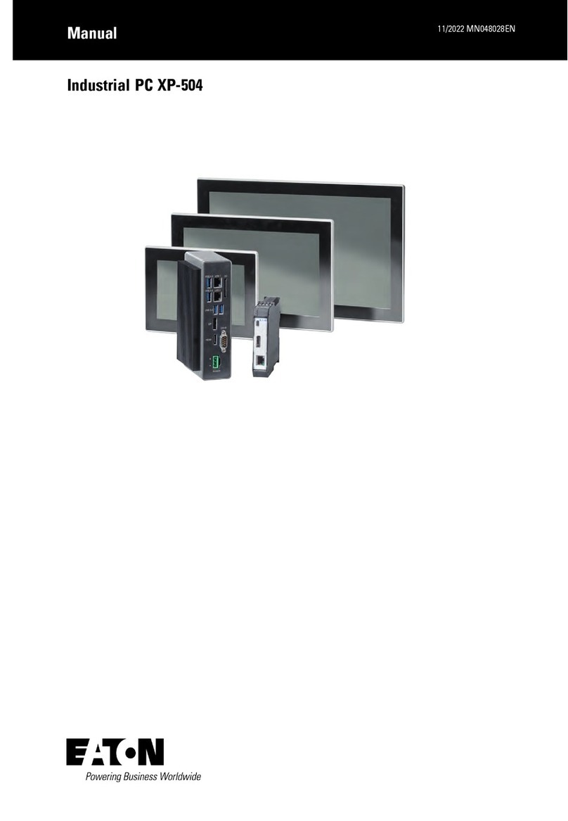
Eaton XP-504-10-A10-A01-2B User manual

Manual 04/2022 MN048028EN
XP-504 Manual

Company information
All brand and product names are trademarks or registered trademarks of their respective own-
ers.
Service
For service and support, please contact your local sales team.
Contact info. Eaton.com/contact
Service page: Eaton.com/aftersales
Original Operating Instructions
is the German-language edition of this document
Publication date
04/2022 3rd edition
Copyright
© 2021 Eaton Automation GmbH, CH-9008 St. Gallen
Author/Editor: Antje Nonnen
Eaton Industries GmbH, Hein-Moeller-Straße 7-11, D-53115 Bonn
All rights, including those of translation, reserved.
No part of this manual may be reproduced, stored in a retrieval system, or transmitted in any
form or by any means, whether electronic, mechanical, photocopying, micro-filming, record-
ing, or otherwise, without the prior written permission of Eaton Industries GmbH, Bonn.
Subject to alteration.

Before starting with the installation
I
lInstallation requires qualified electrician
lDisconnect the power supply of the device.
lSecure against retriggering
lVerify isolation from the supply
lGround and short-circuit
lCover or enclose any
neighboring live parts.
lFollow the engineering instructions (IL) of the
device concerned.
lOnly suitably qualified personnel in accordance
with EN 50110-1/-2 (VDE 0105 part 100) may work on
this device/system.
lBefore installation and before touching the device
ensure that you are free of electrostatic charge.
lThe functional earth (FE) must be connected to the
protective earth (PE) or to the equipotential bon-
ding. The system installer is responsible for imple-
menting this connection.
lConnecting cables and signal lines should be instal-
led so that inductive or capacitive interference
does not impair the automation functions.
lInstall automation devices and related operating
elements in such a way that they are well protected
against unintentional operation.
lSuitable safety hardware and software measures
should be implemented for the I/O interface so that
a line or wire breakage on the signal side does not
result in undefined states in the automation devi-
ces.
lDeviations of the mains voltage from the nominal
value must not exceed the tolerance limits given in
the specifications, otherwise this may result in mal-
function and hazardous states.
lEmergency-Stop devices complying with IEC/EN
60204-1 must be effective in all operating modes of
the automation devices. Unlatching the emergency
switching off devices must not result in an auto-
matic restart.
lBuilt-in devices for enclosures or cabinets must
only be run and operated in an installed state;
desktop devices and portable devices only when
the housing is closed.
lMeasures should be taken to ensure the proper
restarting of programs interrupted after a voltage
dip or outage. This should not result in dangerous
operating states even for a short time. If necessary,
emergency switching off devices should be imple-
mented.
lWherever faults in the automation system may
cause damage to persons or property, external
measures must be implemented to ensure a safe
operating state in the event of a fault or malfunction
(for example, by means of separate limit switches,
mechanical interlocks, etc.).
DANGER!
Hazardous electrical voltage!


Table of Contents
XP-504 Manual 1
Company information 2
Before starting with the installation I
Table of Contents 5
0.1 About this documentation 10
0.1.1 List of revisions 10
0.1.2 Target group 11
0.1.3 Legal disclaimer 12
0.1.4 Device designations and abbreviations 12
0.1.5 Writing conventions 13
0.1.5.1 Warning labels 13
0.1.5.2 Additional user information 14
1. Description 15
1.1 Use as intended 17
1.2 Device models 17
1.2.1 Features on XP-504 PCs 17
1.2.2 Configuration of the XP-504-Widescreen terminal 18
1.2.3 Device variants 18
1.2.3.1 XP-504 series visualization software 18
1.2.3.2 Widescreen terminal sizes 18
1.2.3.3 Interfaces 19
1.3 Nameplate 20
1.4 What the different parts of the part number mean 21
1.5 Accessory devices 23
1.6 Support 23
1.7 Conditions for Underwriters Laboratories Inc. (UL) listing 24
1.7.1 Panel-PC 24
1.7.2 Terminal 24
1.7.3 Terminal with Extender RX 25
1.8 Conditions for Underwriters Laboratories Inc. (UL) listing in haz-
ardous locations - UL-EX 26
XP-504 04/2022 MN048028EN Eaton.com 5

1.9 Use in hazardous locations - ATEX 27
1.10 Marine approvals 28
2. Safety regulations 29
2.1 Basics 29
2.2 Mandatory requirements, personnel requirements 29
2.2.1 Occupational safety 29
2.2.2 Personnel qualifications 29
2.2.3 Information on how to use the device 30
2.2.4 Installation, maintenance, and disposal 30
2.2.5 Prerequisites for proper operation 31
2.3 Device-specific hazards 32
3. Installation 39
3.1 Temperatures 40
3.1.1 Aeration and de-aeration 40
3.2 Installation position 42
3.2.1 Panel-PC, Terminal and Terminal with Extender RX 42
3.2.1.1 Mounting position 42
3.2.1.2 Mounting position 42
3.2.2 Box-PC 44
3.2.2.1 Mounting position 44
3.2.2.2 Mounting position 44
3.2.3 Extender TX 44
3.2.3.1 Mounting position 44
3.2.3.2 Mounting position 44
3.3 Unpacking and checking the equipment supplied 46
3.4 Mounting 49
3.4.1 Panel-PC, Terminal and Terminal with Extender RX 49
3.4.1.1 Preparations 50
3.4.1.2 Installing the Panel-PC and Terminals 53
3.4.2 Box-PC 54
3.4.2.1 Rail mounting 54
3.4.2.2 Mounting wall 55
3.4.3 Extender TX 56
6XP-504 04/2022 MN048028EN Eaton.com

3.5 Preparing the device for operation 57
3.5.1 E lectrical connection 58
3.5.1.1 Functional earthing Widescreen terminal 60
3.5.1.2 Functional earthing Box-PC and Extender TX 62
3.5.2 Power supply via plug connector 63
3.5.2.1 Power supply Panel-PC, Terminal and Terminal with Extender
RX 64
3.5.2.2 Power supply Box-PC 65
3.5.2.3 Power supply Extender TX 66
4. Using peripheral devices - External connections 67
4.1 Layout of interfaces 68
4.1.1 Panel-PC 68
4.1.2 Box-PC 69
4.1.3 Terminal 70
4.1.4 Terminal with Extender RX 70
4.1.5 Extender TX 71
4.2 SD card 72
4.3 USB interfaces 74
4.3.1 USB Host 74
4.3.2 USB-B 75
4.3.3 Mini USB-B 76
4.4 Ethernet 77
4.5 Display interfaces 78
4.5.1 DisplayPort (DP) 78
4.5.2 High Definition Multimedia Interface (HDMI) 79
4.6 Serial interfaces RS232/RS422/RS485 80
4.7 DVI-I 81
5. Commissioning 83
5.1 Initial commissioning 84
5.1.1 Connecting peripheral devices 84
5.2 Running the XP-504 85
6. Operation Touch display 87
6.1 Safety Instructions 87
XP-504 04/2022 MN048028EN Eaton.com 7

6.2 Handling 89
6.3 Touch setup 90
7. Operating System 91
7.1 Windows 91
7.2 Windows 10 Enterprise LTSC 93
7.2.1 Updates 93
7.2.2 Common Functions 93
7.2.3 Dedicated features 93
7.2.3.1 Protect Mode (Operated with two drives, C:\ and D:\) 93
7.2.3.2 Protect-Mode data organization 94
7.2.4 Managing users and configuring the XP-504 95
7.2.5 Modifying an Account Name or Password 96
7.2.6 Device start without user login dialog box 96
7.2.7 License Eaton Galileo-Open Runtime 96
7.2.8 License Eaton Visual Designer Runtime 96
7.2.9 Enabling / disabling IIS communication for Visual Designer 97
7.2.10 Enabling / disabling the automatic screen lock 97
8. Faults 99
9. Maintenance 101
9.1 Cleaning and maintenance 101
9.1.1 Cleaning Multi-touch touch panel 101
9.1.2 Replacing the Battery Panel-PC and Box-PC 101
9.2 Repairs 106
9.3 Storage, transport and disposal 107
9.3.1 Storage and transport 107
9.3.2 Disposal 109
Appendix 110
A.1 Technical data 111
A.1.1 Data sheet 111
A.1.2 Dimension and weight specifications 112
A.1.2.1 XP-504-10-... Panel-PC 112
A.1.2.2 XP-504-15-... Panel-PC 113
8XP-504 04/2022 MN048028EN Eaton.com

A.1.2.3 XP-504-21-... Panel-PC 114
A.1.2.4 XP-504-BOXPC-... Box-PC 115
A.1.2.5 XP-504-10-...Terminal 116
A.1.2.6 XP-504-15-...Terminal 117
A.1.2.7 XP-504-21-...Terminal 118
A.1.2.8 XP-504-10-...Terminal with Extender RX 119
A.1.2.9 XP-504-15-...Terminal with Extender RX 120
A.1.2.10 XP-504-21-...Terminal with Extender RX 121
A.1.2.11 XP-504-EXT module 122
A.1.3 General data 123
A.1.4 Information on the power supply 126
A.1.5 Approvals and declarations 127
A.2 Further usage information 129
Alphabetical index 131
XP-504 04/2022 MN048028EN Eaton.com 9

0.1 About this documentation
This Manual contains all the information you will need in order to use the XP-504
safely and effectively.
The Manual XP-504 manual is considered an integral part of the device and must
always be readily available in the device's close proximity so that users have access
to it.
This Manual describes all of the devices' lifecycle stages: transportation, installation,
commissioning, operation, maintenance, storage, and disposal.
It does not, however, go over the corresponding operating system or application soft-
ware.
Make sure to always use the latest documentation for your device.
The latest version of this documentation, as well as additional references, is availa-
ble for download on the Internet. → Section "Further usage information", page 129
Please send any comments, recommendations, or suggestions regarding this docu-
0.1.1 List of revisions
The following significant amendments have been introduced since previous issues:
Publication
date Page Keyword New Modification Deleted
09/2021 New edition, panel-PC, CE, UKCA ✓
01/2022 Panel-PC, UL approval ✓
04/2022 Device series expanded with box PC,
extender module, terminal, and terminal
with extender
✓
10 XP-504 04/2022 MN048028EN Eaton.com

0.1 About this documentation
0.1.2 Target group
This manual XP-504 is intended for engineers, electricians, and automation tech-
nicians. Electrical engineering and physics-related knowledge and skills will be requi-
red in order to be able to commission the corresponding devices.
CAUTION
Installation requires qualified electrician
Follow the safety instructions for the XP-504!
The section on safety instructions must be read and understood by
everyone who will be working with the XP-504 before the actual work
is performed Human-machine interface.
WARNING
Incomplete documents
Working with individual pages taken out from the information for use
may lead to bodily injury and property damage due to failure to
observe relevant safety information.
Always work with the latest and full document.
XP-504 04/2022 MN048028EN Eaton.com 11

0.1 About this documentation
0.1.3 Legal disclaimer
All the information in this manual has been prepared to the best of our knowledge
and in accordance with the state of the art. However, this does not exclude the pos-
sibility of there being errors or inaccuracies. We assume no liability for the cor-
rectness and completeness of this information. In particular, this information does
not guarantee any particular properties.
Do not use the XP-504 before reading and understanding this manual.
Hazards posed by the XP-504 cannot be eliminated if the safety instructions are not
observed – especially if the XP-504 is installed and commissioned by unqualified per-
sonnel and/or is used improperly. Eaton assumes no liability for any damages resul-
ting from cases such as these.
0.1.4 Device designations and abbreviations
The following general terms are used throughout this manual:
Short designation Explanation
Human-machine interface Human Machine Interface
XP-504 all XP-504 devices
Panel-PC Industrial PC with integrated multi-touch screen for flush mounting
Box-PC Industrial PC for installation on DIN-rail
Terminal Capacitive multi-touch screen for operating HMIs
Extender TX Transmitter module
Terminal with Extender RX Capacitive multi-touch screen for operating HMIs with receiver
For the exact designation for your XP-504, please refer to the→ "Name-
plate", page 20.
12 XP-504 04/2022 MN048028EN Eaton.com

0.1 About this documentation
0.1.5 Writing conventions
Award Description
Bold text Used for all graphical user interface elements
Text Used for the button labels
Menu/command Used for menus and commands on the device
<name> Angle brackets are used to indicate variable values
that you must replace with your own values
0.1.5.1 Warning labels
Risk of personal injury warning.
DANGER
Warns of hazardous situations that result in serious injury or death.
WARNING
Warns of the possibility of hazardous situations that could result in
serious injury or even death.
DANGER!
Dangerous Electrical Voltage!
CAUTION
Warns of the possibility of hazardous situations that can cause injury.
Property damage warning
CAUTION
Warns about the possibility of material damage.
Prohibited uses, actions, etc.
Explains the prohibition
Bid
Explains the instruction
XP-504 04/2022 MN048028EN Eaton.com 13

0.1 About this documentation
Notes
Indicates useful tips.
Indicates instructions to be followed
Additional information, background information,
information worth knowing, useful additional information
0.1.5.2 Additional user information
Documents (such as manuals) are listed after the icon together with the cor-
responding name and Eaton number.
Publication title For identifying the Eaton publication code
External Internet addresses. They will be shown after the icon.
Destination address
14 XP-504 04/2022 MN048028EN Eaton.com

1. Description
1. Description
XP-504 devices can be used as control and monitoring devices.
XP-504 devices are the answer to the growing demand of machine and system manu-
facturers for high-precision, cost-effective HMI solutions with industrial-grade capa-
citive multi-touch technology. Accordingly, the XP-504 series offers Widescreen
terminals with sizes of 10.1", 15.6", and 21.5". Their slim design, featuring a non-reflec-
tive glass front, delivers a modern look. Finally, the robust, scratch-resistant front and
open device concept on XP-504 devices make them suitable for use in virtually all
branches of industry related to mechanical and plant engineering.
The XP-504 series features a modular design that makes it possible to put together
custom solutions out of standard components:
Fig. 1: XP-504 devices
lPanel-PC: PC with integrated Multi-touch touch panel
lBox-PC: Compact DIN-rail PC
lTerminal: Remote Multi-touch touch panel
lExtender TX: Transmitter module for transmitting video and USB data
lTerminal with Extender RX: Remote Multi-touch touch panel with integrated video
and USB data receiver
The II 3D Ex tc IIIC T70°C U ATEX certification applies to devices with a Widescreen
terminal:
Panel-PCs, Terminals, and Terminal with Extender RX.
Panel-PC
Terminal
Terminal with Extender RX
Box-PC Extender TX
XP-504 04/2022 MN048028EN Eaton.com 15

1. Description
Fig. 2: Series overview
Combining XP-504 devices with each other
Each PC can be connected to a maximum of two terminals.
Each Panel-PC or Box-PC can be expanded with two Terminals, two Terminal with
Extender RX, or one Terminal and one Terminal with Extender RX.
When choosing devices, it is necessary to take into account the distances between
the devices and the connections between them. An Extender TX module needs to be
used for distances greater than 1.8 m.
Fig. 3: Device concept overview
16 XP-504 04/2022 MN048028EN Eaton.com

1. Description
1.1 Use as intended
1.1 Use as intended
The devices of the XP-504 series are primarily intended for use in machine and sys-
tem building applications.
They are suitable for use in industrial environments and are typically used indoors for
automation purposes.
Any other use must be discussed and agreed upon with the manufacturer in
advance.
Using the device in a way not specified by the manufacturer may negatively affect
the protection provided by the device.
Bid
Each device in the XP-504 series must be used only in locations for
which this series of devices is approved. Make sure to read and fol-
low the information and labels on the nameplate for the devices, as
well as section Approvals and declarations in the appendix.
Prohibited uses, actions, etc.
It is strictly prohibited to use the device in order to implement safety-
relevant functions (in the sense of personal and machine protection).
1.2 Device models
1.2.1 Features on XP-504 PCs
The PCs' computer core is always the same. Every Panel-PC and every Box-PC fea-
tures:
1. Powerful CPU, processor Intel Atom QuadCore E3950 2GHz
2. MSATA memory 64 GB mSATA
3. SD memory card slot for 8 GB SD card
4. Operating System Windows 10 Enterprise LTSC, IoT, 64 bit, 8GB DDR3 RAM
5. Integrated interfaces:
l2 x Ethernet ports (1000/100/10 Mbps Ethernet / GbE-Ethernet) for use as a
communication or field bus interface
l4x USB 3.0
lOne RS232/RS422/RS485 (COM) port for communicating with PLCs or devi-
ces,
l1x DisplayPort
l1x HDMI
XP-504 04/2022 MN048028EN Eaton.com 17

1. Description
1.2 Device models
Up to two Widescreen terminal terminals of the XP-504 series can be connected to
each XP-504 PC.
1.2.2 Configuration of the XP-504-Widescreen terminal
In addition, every Widescreen terminal is a Color display, TFT and can be used with
gestures (Multi-touch touch panel).
In order for this functionality to work properly, you must press on the Projected
Capacitive Touch (PCT) display with a finger or stylus.
The USB Type-B port on the Terminal is required for the touch func-
tionality and cannot be used for anything else.
1.2.3 Device variants
1.2.3.1 XP-504 series visualization software
The Panel-PC and Box-PC configurations differ from each other in terms of the run-
time license for the optional visualization software – Galileo Open or Visual Designer.
1.2.3.2 Widescreen terminal sizes
Panel-PCs, Terminals, and Terminal with Extender RX are available in various display
sizes.
lXP-504-10-... - Screen diagonal 10.1" (25.65 cm),
Screen mode: 16:10, visible screen area 216.96 mm x 135.26 mm, 1280 x 800 px
lXP-504-15-... - Screen diagonal 15.6" (39.6 cm),
Screen mode: 16:9, visible screen area 344.23 mm x 193.54 mm, 1366 x 768 px
lXP-504-21-... - Screen diagonal 21.5" (54.6 cm),
Screen mode: 16:9, visible screen area 476.06 mm x 276.79 mm, 1920 x 1080 px
Fig. 4: Display size comparison
18 XP-504 04/2022 MN048028EN Eaton.com

1. Description
1.2 Device models
1.2.3.3 Interfaces
The number and type of interfaces on the devices in the XP-504 series varies.
Panel-PC/
Box-PC Terminal Terminal with
Extender RX Extender TX
2 x Ethernet,
4 x USB3.0,
1 x
RS232/RS422/485,
1 x HDMI,
1 x DP,
Slot for SD card
1 x USB Type-B (used by the
touch functionality)
1 x DVI-I,
1 x DP
1 x RJ45 (Extender
RX)
1 x RJ45 (Extender TX),
1 x Mini USB-B,
1 x DP
XP-504 04/2022 MN048028EN Eaton.com 19

1. Description
1.3 Nameplate
1.3 Nameplate
The device has a nameplate on rear.
This nameplate includes the following information:
Fig. 5: Example: nameplate on Panel-PC
lManufacturer
lPart number
lPart-No.
lPower supply requirement
lSerial-No.
lType approval and certification marks and information
lLayout of interfaces
To get fast and effective support, make sure to always provide Customer Service
with the following information from the nameplate:
lArticle No. (part No. or article No.)
lSerial No.
20 XP-504 04/2022 MN048028EN Eaton.com
This manual suits for next models
15
Table of contents
Other Eaton Industrial PC manuals
Popular Industrial PC manuals by other brands

SYSTEM Electronics
SYSTEM Electronics COPILOT PB user manual

Siemens
Siemens SIMATIC IPC547J operating instructions

AXIOMTEK
AXIOMTEK IPC932-230-FL Series Quick installation guide

Siselectron
Siselectron SNM2410 manual

IPCOMM
IPCOMM IPC191V2WIN Operating, maintenance and installation manual

Neousys Technology
Neousys Technology SEMIL-1700GC Series Quick installation guide