Eaton xStorage Compact 20 kW User manual

xStorage Compact
Eaton xStorage Compact
Energy Storage System
20 kW–40 kW
Installation Manual

EATON XSTORAGE COMPACT INSTALLATION MANUAL P-16400097 - September 2020 www.eaton.com 2
This manual contains important instructions that must be followed during the installation of Eaton
xStorage® Compact energy storage system. All instructions must be read before installing and operating
the equipment. Save this manual for future reference.
Note that xStorage systems must only be installed by certied Eaton personnel, that is, an Eaton
customer service engineer or Eaton’s certied installer, and that there are no user serviceable parts in
the Eaton xStorage Compact system. If these requirements are violated, the warranty provided will not
apply and Eaton will not be held legally accountable.
This product is intended only for commercial and industrial applications. The contents of this manual are
the copyright of the publisher and may not be reproduced (even extracts) without the written approval of
Eaton. Every care has been taken to ensure the accuracy of the information contained in this manual,
but no liability can be accepted for any errors or omission. The right to make design modications is
reserved.
Compatibility
This document is compatible with Eaton xStorage battery and power conversion system documentation.
Approvals and version history
REVISION DATE DESCRIPTION OF CHANGE APPROVED BY
001 23.09.2020 First issue Eugene van Rooyen
These are the original instructions.

EATON XSTORAGE COMPACT INSTALLATION MANUAL P-16400097 - September 2020 www.eaton.com 3
Contents
1 How to read this manual..................................................................................................................... 5
1.1 Safety-related signs ................................................................................................................... 5
1.2 Symbols and abbreviations........................................................................................................ 5
1.3 Conventions used in this document ........................................................................................... 7
2 Safety instructions .............................................................................................................................. 8
2.1 General safety instructions......................................................................................................... 8
2.2 Warnings and cautions related to logistics................................................................................. 8
2.3 Warnings and cautions related to installation............................................................................. 9
2.4 Battery installation re safety ................................................................................................... 11
3 Introduction to Eaton xStorage Compact ......................................................................................... 12
3.1 System description and main components .............................................................................. 12
3.1.1 Electrical system diagram ............................................................................................ 13
3.2 Looking inside the Eaton xStorage Compact 20 kW - 40 kW .................................................. 14
3.3 Battery system ......................................................................................................................... 14
3.4 External battery rack ................................................................................................................ 16
3.5 System controller and communication box .............................................................................. 17
3.6 Application controller................................................................................................................ 17
4 Site requirements and unpacking..................................................................................................... 19
4.1 Location and cooling requirements .......................................................................................... 19
4.2 Dimensions .............................................................................................................................. 20
4.3 Unpack the xStorage Compact system.................................................................................... 21
5 Installation and cabling..................................................................................................................... 25
5.1 Before you start........................................................................................................................ 25
5.2 Install the xStorage Compact unit ............................................................................................ 25
5.3 Install battery packs ................................................................................................................. 25
5.4 AC and DC cabling of the energy storage system ................................................................... 29
5.4.1 AC and DC cable connections ..................................................................................... 30
5.4.2 AC and DC cable cross-section requirements ............................................................. 30
5.4.3 Minimum recommended fuse sizes ............................................................................. 31
5.5 Install a remote EPO switch..................................................................................................... 31
5.6 Communication interface connections ..................................................................................... 31
5.6.1 Customer communication interface ............................................................................. 32
5.6.2 Remote access for Eaton technical support ................................................................ 33
5.6.3 Digital signal inputs and outputs .................................................................................. 33
5.6.4 General alarm relay output .......................................................................................... 33
5.6.5 Internal communication connections............................................................................ 33
5.6.6 Battery breaker wiring .................................................................................................. 33
5.7 CAN cabling of internal battery packs...................................................................................... 33
5.8 Installing the external battery rack ........................................................................................... 35
5.9 Installation and cabling of grounding ....................................................................................... 40
5.9.1 Earth cabling inside the energy storage system .......................................................... 41
5.9.2 Earth cabling inside the external battery rack .............................................................. 43
5.10 Wiring parallel xStorage Compact energy storage systems .................................................... 45
5.11 Install the interface connections............................................................................................... 45
5.12 First time system start-up......................................................................................................... 46
6 Technical data .................................................................................................................................. 47
6.1 About technical data................................................................................................................. 47

EATON XSTORAGE COMPACT INSTALLATION MANUAL P-16400097 - September 2020 www.eaton.com 4
6.2 Eaton xStorage Compact 20 kW - 40 kW energy storage system, technical specications .... 47
6.3 Battery pack, technical specications ...................................................................................... 50
APPENDIX A: Example of xStorage Compact connected to TN-C earthing system.................................... 53
EATON XSTORAGE COMPACT INSTALLATION MANUAL P-16400097 - September 2020 www.eaton.com 5
1 How to read this manual
1.1 Safety-related signs
These are the safety-related signs used in this document.
DANGER
DANGER indicates a hazard with a high level of risk which, if not avoided, will result
in serious injury or death.
WARNING
WARNING indicates a hazard with a medium level of risk which, if not avoided,
could result in serious injury or death, or damage to the machine.
CAUTION
CAUTION indicates a hazard with a low level of risk which, if not avoided, could
result in minor or moderate injury, or damage to the machine.
NOTE: Notes are used to indicate important information and useful tips.
1.2 Symbols and abbreviations
Hazard symbols
These symbols indicate a hazardous situation or action. Symbols are used to warn of situations, which
can cause environmental damage and personal injury.
General warning sign
Fire hazard
Battery hazard
Corrosive hazard
Electrical hazard

EATON XSTORAGE COMPACT INSTALLATION MANUAL P-16400097 - September 2020 www.eaton.com 6
Prohibited action symbols
These symbols are used in warnings and notications to indicate an action that should not be taken. The
prohibited action symbols are shown below.
No smoking
Limited or restricted access
General symbol for prohibited action
Do not touch
Mandatory action symbols
These symbols are used in warnings and notications to indicate an action that must be taken. The
mandatory action symbols are shown below.
Wear eye protection
General symbol for mandatory action
Read the manual or instructions
Disconnect from power source
First aid

EATON XSTORAGE COMPACT INSTALLATION MANUAL P-16400097 - September 2020 www.eaton.com 7
Pb
Batteries marked with this sign must be recycled
1.3 Conventions used in this document
This document uses the following type conventions:
Bold type highlights important concepts in discussions, key terms in procedures and menu options, or
represents a command or option that you type or enter at a prompt.
Italic type highlights notes and new terms when they are dened.
Screen type represents information that appears on the screen or LCD.

EATON XSTORAGE COMPACT INSTALLATION MANUAL P-16400097 - September 2020 www.eaton.com 8
2 Safety instructions
2.1 General safety instructions
DANGER
Important safety instructions. Keep these instructions.
These safety guidelines contain essential information that you must obey during the installation of
the xStorage® Compact Energy Storage System (ESS). Carefully read and understand these safety
instructions before you operate the ESS unit and the battery packs/racks.
The ESS is designed for indoor applications, and contains safety shields behind the door and front
panels. However, the ESS is a sophisticated power system and should be handled with appropriate
care. Install xStorage Compact ESS only in a dry, indoor environment, free of conductive contaminant.
Installation can be done only by Eaton customer service engineer or Eaton’s certied installer who must
fully understand and apply provided safety instructions to avoid electric hazard shock, potential death
and severe product damage. Certied installer must be an electrician who has national authorization
to make electrical installations in that particular country. Commissioning can be done only by Eaton
customer service engineer or Eaton’s certied partner who has completed xStorage Compact ESS
service training.
You can install the xStorage battery packs only within the Eaton xStorage battery rack and connect them
with the Eaton xStorage energy storage systems. Install the rack only on a non-ammable oor.
2.2 Warnings and cautions related to logistics
WARNING
Do not lift any of the packed or unpacked units without help or an adequate
machine lifter. There is a risk of injury.
If a package falls to the oor, it causes irreversible damage to the product. A
package falling on the handler of the unit could lead to death.
When you load, lift, store and deliver products, avoid uncontrolled product
movements. These could harm both the product and the handler of the units.
Pack the products carefully to prevent any product damage during the transport.
Transport the battery pack in its original packaging, in an upright position.
Compliant, non-ammable material must be used to protect the battery pack from
impact damage.
When transporting battery packs, do not pack more than 2 pallets with products
on top of each other. A single pallet contains 3 rows of products, that is, 3 packed
on top of each other, distributed in 2 side-to-side columns. If the stocked number
of packages exceeds the dened number, there is a higher risk of damaging the
products.
EATON XSTORAGE COMPACT INSTALLATION MANUAL P-16400097 - September 2020 www.eaton.com 9
CAUTION
The battery packs and ESS units are heavy. Wear safety shoes and preferably use
an adequate machine lifter for handling operations.
It is recommended that at least two persons work together for all handling opera-
tions such as loading, lifting, moving packed units through the warehouse, and also
delivery and unloading.
Always store packages in a dry and humidity-controlled environment (a storage
temperature of 20 °C and humidity of 50 % - 60 % is recommended). Store the
packages away from leaking liquids.
Make sure that no foreign objects penetrate the battery pack packaging.
If you drop the packaging, report it immediately to the responsible personnel. The
responsible personnel must then carry out a product quality control check and make
sure that the fall or impact did not cause any damage to the product.
Do not leave packed products outside. Extreme weather might cause severe
product damage.
2.3 Warnings and cautions related to installation
DANGER
The xStorage Compact ESS must be installed in a temperature and humidity-con-
trolled indoor environment that is free of conductive contaminants. Never install the
xStorage Compact ESS in an airtight room, or in the presence of ammable gases,
or in an environment that exceeds the specications. Never install the xStorage
Compact ESS outdoors as the system is not intended for outdoor use. Excessive
amount of dust in the operating environment of the xStorage Compact ESS may
cause damage or lead to malfunction.
The allowed ambient temperature range for the system is from 0 °C to +35 °C (+30
°C for Gen1 and Gen2 batteries). The ambient temperature must not exceed 35 °C,
especially for 10 or more consecutive days.
Do not install and operate the xStorage Compact ESS near water or in places with
excessive humidity, for example, where the maximum relative humidity is 95 %.
Prior to starting any installation or service work, disconnect all AC and DC power
sources. Also ensure system grounding/PE continuity.
Do not open or mutilate the ESS or the battery pack.
If you accidentally drop a battery pack, immediately move to minimum safe distance
of ve meters. Prepare foam re extinguishers in case the battery pack cells ignite
from the impact. Immediately inform your Eaton technical support representative.
In case of re, immediately contact the re brigade. Keep a safe distance from
the hazard scene due to the potential risk of being exposed to toxic fumes. Avoid
inhaling smoke and inform all the people in the near vicinity not to enter the hazard
area.
DANGER
In case of spillage incidents (battery pack leakage), move at least ve meters away
from the leakage point. Inform your Eaton technical support representative and the
re brigade. Keep away from the hazard area. The disposal of the battery must be
handled by certied personnel.
In the event of electrolyte contamination by exposure to uncovered battery material
(for example, electrolyte or powder), immediately ush the skin and eyes with plenty
of clean water and immediately remove any contaminated clothing. Also, request
immediate medical assistance.
EATON XSTORAGE COMPACT INSTALLATION MANUAL P-16400097 - September 2020 www.eaton.com 10
WARNING
Before you energize the installed xStorage Compact ESS and battery packs, make
sure that the battery - or + terminals are not accidentally grounded in any part of the
system. Make sure that each battery pack chassis, the Eaton xStorage battery rack
and the ESS have properly installed grounding according to instructions.
Never block the natural air ow around the system. After installation, do not place
anything on top of the system or near the sides of the system.
Never expose the xStorage Compact ESS and battery packs to direct sunlight or to
any heat source.
If you need to store the xStorage Compact ESS and battery packs prior to installa-
tion, make sure to store them in a dry place away from exposure to sun and rain.
Make sure that you secure the ground line to the ground of the grid. Make sure that
you do not confuse the line and neutral with ground.
Do not attempt to alter any battery pack wiring or connectors. Attempting to alter the
wiring can cause injury and will void the warranty of the system.
CAUTION
The battery pack and other xStorage Compact ESS components are heavy. Wear
safety shoes and preferentially use a vacuum lifter for handling operations.
All handling operations require at least two persons for unpacking, lifting and instal-
lation.
Carefully unpack battery packs and avoid any excessive movements which might
lead to product damage and severe injury.
Obey all the necessary handling precautions. Wear rubber gloves, boots and use
adequate installation tools.
Do not place tools, metal parts or anything else on top of the unpacked or mounted
battery pack.
Make sure that you install battery packs only in the Eaton xStorage battery rack.
CAUTION
High touch current.
Maximum touch current in the PE conductor exceeds the limit of 3.5 mA.
CAUTION
Compatibility with residual current-operated protective devices (RCDs).
This product can cause a DC current in the PE conductor. Where a residual current-
operated protective device (RCD) is used for protection against electrical shock,
only an RCD of Type B is allowed on the supply side of this product.
WEAR PROTECTION GEAR
Wear suitable eye protection when working with or around lithium batteries.

EATON XSTORAGE COMPACT INSTALLATION MANUAL P-16400097 - September 2020 www.eaton.com 11
2.4 Battery installation fire safety
WARNING
Battery hazard.
WARNING
Fire hazard.
The risk of battery re for xStorage battery pack installations is extremely limited by the design of the
batteries and the operation of the system. The UN38.3 tests, carried out on individual battery modules
and the entire battery pack, conrm the resistance of our equipment at low pressures, at extreme
temperatures [-40 °C to 72 °C], shock and vibration as well as external short circuit or overloads or
discharges outside specication. However, the risk of re exists and toxic compounds related to lithium-
ion technology can be released during the combustion of batteries as written in the battery safety sheet.
Eaton recommends the installation of energy storage systems in rooms closed to the public, not subject
to ooding, having a certain reproof capacity, as well as appropriate ventilation to allow fumes to escape
into a safe area (not occupied by the public). Make sure that there is an active automatic re detection
system in place with early warning smoke detection and appropriate extinguishers for re suppression.
In the unlikely event of a thermal runaway by a battery, Eaton recommends leaving the battery room,
closing doors, access, or windows while ensuring that ventilation is turned on and the xStorage
Compact energy storage system is shut down. It is recommended to let the battery burn and not to try to
extinguish it with the standard means provided (water or re extinguisher) because the increase of risk to
the people or the equipment.
If the source of the re is caused by a battery, the re should extinguish by itself, relatively quickly. It is
important to notify the emergency services. The emergency services are the only authority to determine
whether the battery part is safe again and that the cleaning and replacement can be done by qualied,
responsible parties. Eaton recommends a waiting time of one hour between the end of the smoke and
entry into the battery room.
In the event of a building re that extends into the battery room, it is important to inform the emergency
services of the presence of an energy storage system with lithium-ion batteries. Indeed, if the re
protection services were to ght the re in the battery room, it should be equipped with hazardous
material protection to guard against potential releases of toxic compounds according to the procedures
in force during re involving electric cars.
EATON XSTORAGE COMPACT INSTALLATION MANUAL P-16400097 - September 2020 www.eaton.com 12
3 Introduction to Eaton xStorage Compact
This chapter describes the main components and sub-system of the Eaton xStorage Compact Energy
Storage System (ESS).
3.1 System description and main components
The Eaton xStorage Compact 20 kW - 40 kW is a single rack energy storage system (ESS). It is a
modular and scalable solution for various energy storage applications in high-end residential, commercial
and light industrial buildings.
The Eaton xStorage Compact 20 kW - 40 kW consists of several subsystems and components:
• Power conversion system (PCS)
The bi-directional inverter drives AC load and charges DC batteries from the grid. The inverter
discharges the DC battery and supplies power into the AC grid when required.
• Battery system
The xStorage Compact ESS includes one string of internal batteries, consisting of ve battery
packs: one primary battery pack and four battery packs. A distributed battery management system
(BMS) controls charging and discharging of the battery modules, protecting the unit from operating
outside its safety limits in terms of voltage, current and temperature. For more battery capacity, you
can add an external 42U high battery rack to the xStorage Compact ESS. You can install up to 10
battery packs (one primary battery pack + 9 battery packs) in the external battery rack.
• Communication box
The communication box consist of all necessary components for the overall system control and
management, internal and external communication interfaces and auxiliary power supplies.
• Application controller
A touch screen display and control panel for operating and conguring the system.
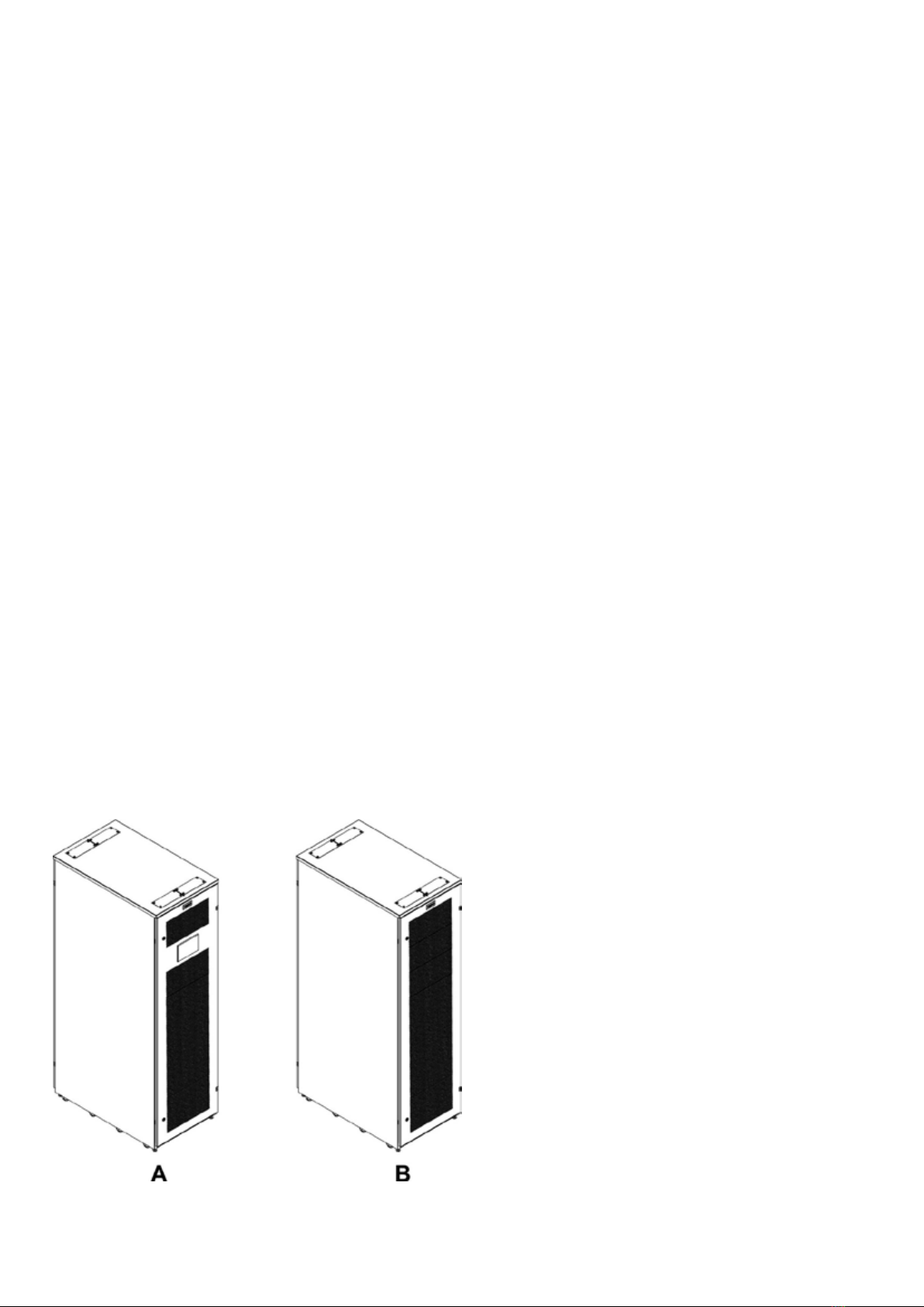
Figure 1. Eaton xStorage Compact Energy Storage System (ESS)
A Eaton xStorage Compact 20 kW - 40 kW
B External battery rack
EATON XSTORAGE COMPACT INSTALLATION MANUAL P-16400097 - September 2020 www.eaton.com 13
3.1.1
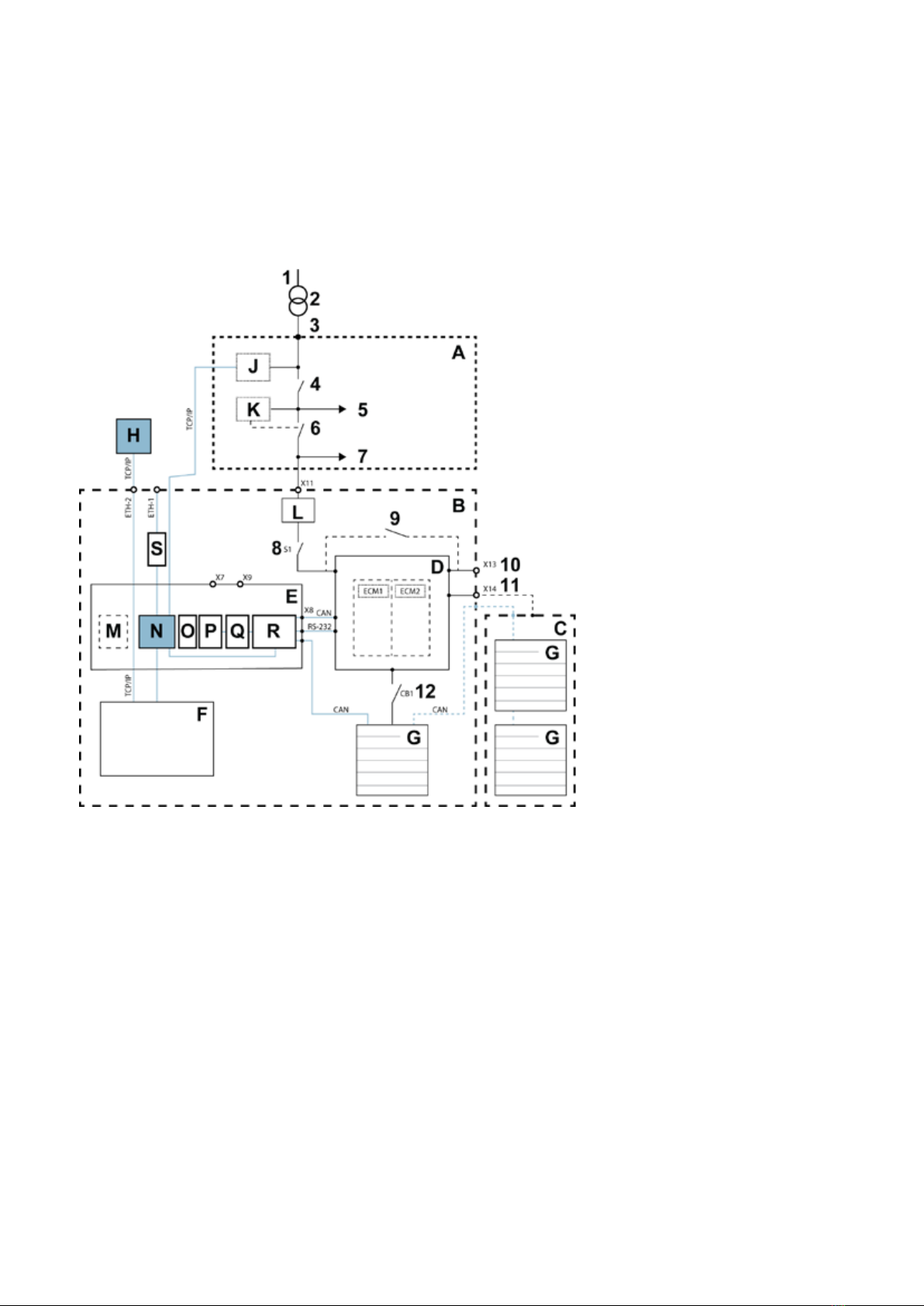
Electrical system diagram
The diagram describes electrical connections to a distribution network, loads and communication
interfaces at the generating plant.
Figure 2. Electrical connections and communication interfaces for xStorage Compact power conversion system and
external battery rack
1 Distribution network G Battery string
2 Medium Voltage/Low Voltage transformer H Customer connectivity gateway
3 Point of connection J External power meter
4 Main switch of a generating plant K Interface protection relay
5 Generating plant non-island operation (option) L Surge protection device
6 Interface switch M Ground fault detection (option)
7 Generating plant island operation (option) N Ethernet switch
8 Input switch S1 O Auxiliary power supply units (PSUs)
9 Maintenance bypass switch (MBS) (optional) P I/O module
10 Connection to the critical load (back-up) Q Relay module
11 Connection to the external battery cabinet R System controller
12 Battery breaker CB1 S Service gateway
A Generating plant LV switchgear ETH-1 Service gateway connection
B xStorage Compact cabinet ETH-2 Customer gateway connection
C External battery rack X7 Interface protection and customer I/Os
DPower Conversion System unit (ECM = energy
conversion module) X8 Internal communication connections
E Communication box X9 Battery breaker status signals
F Application controller/control panel X11 Mains connection to the grid

EATON XSTORAGE COMPACT INSTALLATION MANUAL P-16400097 - September 2020 www.eaton.com 14
3.2 Looking inside the Eaton xStorage Compact 20 kW - 40 kW
Figure 3. Front view of the the Eaton xStorage Compact 20 kW - 40 kW
1 Door latch 7 20 kW ECM power modules
2 Application controller touch screen display 8 Maintenance bypass switch (MBS) (optional)
3 Communication box (system controller) 9 230Vac Aux. voltage, F1 and F2
4 Front panel of the communication box 10 Battery breaker, CB1 (internal)
5 Communication interfaces 11 Primary battery pack
6 Mains switch 12 Battery pack
3.3 Battery system
The battery system includes:
• internal batteries (1 battery string)
• external batteries (external battery rack with up to 2 battery strings)
A string includes 4 battery packs and 1 primary battery pack, a total of 5 packs in series. The xStorage
Compact unit contains 1 battery string. The external battery rack can contain 1 or 2 strings (1 primary
battery pack and 4 or 9 battery packs). With the external battery rack, the energy capacity can be tripled,
see Table 2. Number of battery strings based on energy capacity.
Each battery pack is a combination of several battery modules, fuse and sensors internally connected to
a battery management system (BMS). The BMS manages the complete battery pack by monitoring its
state, voltage, current and temperature, calculating secondary data, SOC, reporting that data, protecting
the battery, monitoring its environment and balancing cells.
The main difference between the primary battery pack and a battery pack is the capability to open the
string contactor in case of alarms/events on a string of battery packs. The primary battery pack has two
independent contactors for two parallel battery strings.
EATON XSTORAGE COMPACT INSTALLATION MANUAL P-16400097 - September 2020 www.eaton.com 15
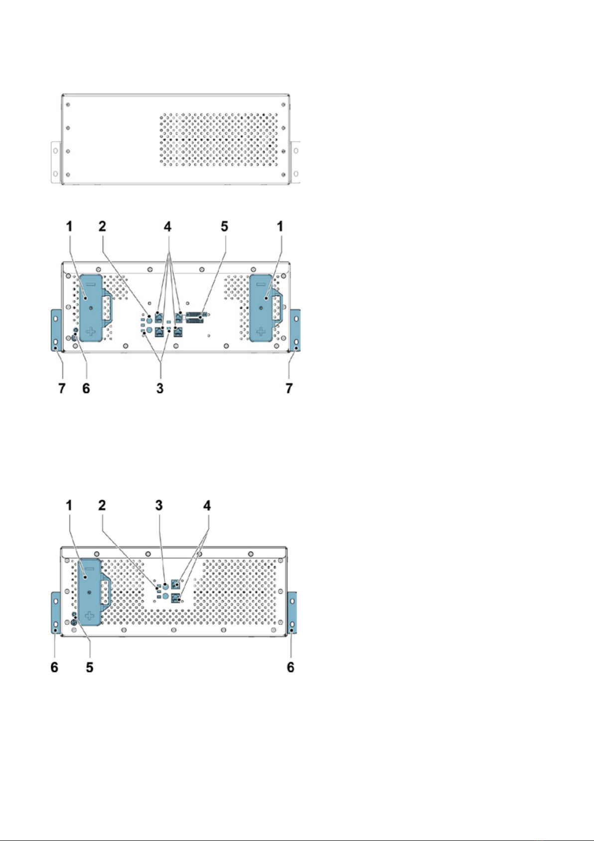
Figure 4. Battery pack, back side
Figure 5. Primary battery pack, front side
1 Battery terminals 5 System connectors
2 Battery ID rotary switches 6 Grounding screw hole
3 LED status 7 Mounting brackets
4 CAN terminals (RJ45)
Figure 6. Battery pack, front side
1 Battery terminals 4 CAN terminals (RJ45)
2 LED status 5 Grounding screw hole
3 Battery ID rotary switches 6 Mounting brackets
EATON XSTORAGE COMPACT INSTALLATION MANUAL P-16400097 - September 2020 www.eaton.com 16
3.4 External battery rack
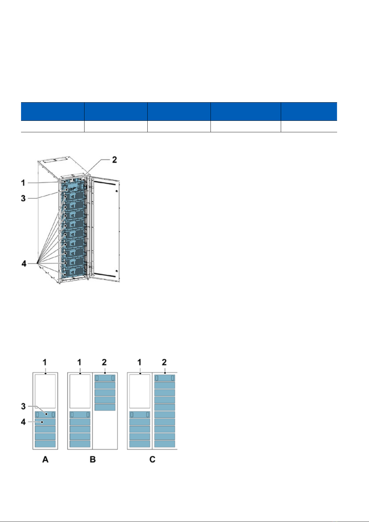
The external battery rack consists of a nineteen inches wide rack mount 42U high cabinet with multiple
mounting slots designed to house the battery packs secured in place with screws.
Table 1. Battery rack dimensions
Width (mm) Depth (mm) Height (mm) Weight (kg) (without
battery packs) Rack units
600 1000 1987 150 42U
Figure 7. External battery pack with battery packs installed
1 Battery breaker for lower string 3 Primary battery pack
2 Battery breaker for upper string 4 Battery pack
One battery string (1 primary battery pack and 4 battery packs) is installed in the Eaton xStorage
Compact 20 kW - 40 kW unit. Up to 2 battery strings (1 primary battery pack and 4 or 9 battery packs)
can be installed in the external battery rack for more energy capacity.
Figure 8. Battery power options A, B and C
1Eaton xStorage Compact 20 kW - 40 kW unit with PCS
electronics module 3 Primary battery pack
2 External battery rack 4 Battery pack

EATON XSTORAGE COMPACT INSTALLATION MANUAL P-16400097 - September 2020 www.eaton.com 17
The number of battery strings is determined by the energy capacity (kWh) requirements of the project.
Table 2. Number of battery strings based on energy capacity
Battery technology
Number of strings / Battery power options
1
Option A
2
Option B
3
Option C
Nominal capacity
(kWh)
GEN1 (2nd life) 21 42 63
GEN2 30 60 90
GEN4 50 100 150
3.5 System controller and communication box
The system controller and its related components are physically placed in the communication box. The
system controller enables the communication and monitoring of data.
The main components in the communication box are:
• System controller unit (Eaton XC-303)
• Relay output and I/O modules (Eaton XN322) that offer digital inputs for monitoring the breaker and
relay status, auxiliary relay outputs to activate battery pack wake-up signals, and circuit breaker
tripping
• Ethernet switch (Eaton PXE 6-port switch 10/100 Mb) that connects the xStorage system with the
external communication and management system
• 24 Vdc and 12 Vdc auxiliary power supplies to feed the system controller and the related compo-
nents
• Terminal blocks to ensure proper connections
The system controller is based on the Eaton XC-303 modular PLC hardware. It is expanded centrally by
XN322 slice modules. The system controller enables the communication and monitoring of data from the
different devices connected to the internal CAN bus.
The main functionality of the system controller unit is to:
• acquire, consolidate and monitor available data from the battery packs and power conversion
system (PCS)
• control PCS operation
• control battery system operation
• manage various grid connection functions
• enable connectivity with the application controller or client controller
3.6 Application controller
The control panel of the Eaton xStorage Compact system is a 7-inch color touch screen. It is a dual-
purpose device, providing both a local user interface for the control of the single xStorage Compact unit,
and the means to manage application-specic functions of the larger energy storage system.
As default, the control panel is placed on the front door of the system cabinet. As an option, the xStorage
Compact system is also available without the control panel.
In systems with multiple parallel Eaton xStorage Compact units, only a single application controller is
needed to manage all units.

EATON XSTORAGE COMPACT INSTALLATION MANUAL P-16400097 - September 2020 www.eaton.com 18
The application controller offers several standard control algorithms, for example:
• measurement reading from power meters
• control and monitoring of PV systems
• storage control, for example self-consumption or peak shaving on a user-dened programmable
schedule
• customizable control functionality
• conguration of several grid connection parameters
The application controller can monitor and control a generating plant of up to 5 parallel connected
xStorage Compact systems. For more information, refer to the Eaton xStorage C&I Application controller
user guide.

EATON XSTORAGE COMPACT INSTALLATION MANUAL P-16400097 - September 2020 www.eaton.com 19
4 Site requirements and unpacking
4.1 Location and cooling requirements
The xStorage Compact ESS installation requires a TN-S, TN-C-S, TN-C or TT power distribution system.
The ESS installation must meet the following guidelines:
• The system must be installed on a level oor. The oor must be suitable for heavy weight and
wheeling.
• The system must be installed in a temperature and humidity controlled indoor area that is free of
conductive contaminants.
• The cabinet can be installed in line-up-and-match or standalone congurations. If you do not obey
these guidelines the warranty may become void.
Table 3. Location and environmental requirements
Requirement Value
Ambient temperature range From 0 °C to 35 °C
Recommended operating range From 20 °C to 25 °C
Maximum relative humidity 95 %, non-condensing
Maximum altitude 2,000 m
For ventilation requirements, see xStorage Compact heat rejection in Table 4. Air conditioning or ventila-
tion requirements of the xStorage Compact 20 kW and 40 kW ESS during full load operation.
Table 4. Air conditioning or ventilation requirements of the xStorage Compact 20 kW and 40 kW ESS during full load
operation.
Heat rejection (kW)
Internal batteries xStorage Compact 20 kW xStorage Compact 40 kW
GEN 1 (2nd life) 1.15 2.12
GEN 2 1.15 2.16
GEN 4 1.2 2.77
The total cooling requirements of an external battery rack must be calculated considering the cooling
requirements for each battery, see Table 5. Cooling requirements for an external battery rack (EBR)
including 10 battery packs.
Table 5. Cooling requirements for an external battery rack (EBR) including 10 battery packs
Battery technology
Maximum initial cooling requirement per battery rack at 1C (kW)
25 % load 50 % load 75 % load 100 % load
GEN1 (2nd life) 0.15 0.29 0.52 0.84
GEN2 0.15 0.31 0.56 0.92
GEN4 0.23 0.61 1.25 2.14
EATON XSTORAGE COMPACT INSTALLATION MANUAL P-16400097 - September 2020 www.eaton.com 20
4.2 Dimensions
Figure 9. Eaton xStorage Compact system and external battery rack dimensions
A Eaton xStorage Compact 20 kW – 40 kW
B External battery rack
Figure 10. Package dimensions with center of gravity marked
Table 6. xStorage Compact system and battery cabinet minimum clearances
Clearance Value (mm)
From front of rack 900
From back of the rack 200
From top of the cabinet minimum 300
Side to side 0
The xStorage Compact system and the external battery cabinet must be placed side by side.
This manual suits for next models
1
Table of contents
Other Eaton Storage manuals

Eaton
Eaton xStorage Home 3P User manual

Eaton
Eaton Cutler-Hammer SRAM PC104 User manual

Eaton
Eaton xStorage Home 3P User manual

Eaton
Eaton xStorage Home 3P User manual

Eaton
Eaton xStorage 400 User manual

Eaton
Eaton RE Series User manual

Eaton
Eaton C-632X User manual

Eaton
Eaton Cutler Hammer SRAM PC104 User manual

Eaton
Eaton xStorage Compact User manual

Eaton
Eaton xStorage Home 3P User manual


