The Specialist In Drum Handling Equipment
310 Series
Tilt-To-Load Drum Rotators
Operator’s Manual for Morse 310 Series Tilt-To-Load Drum Rotators
Serial Number 276434 to 283820
morsedrum.com
Copyright 2016 - Morse Mfg. Co., Inc. Form PL310 (276434-283820) (Updated March 26, 2018 3:09 PM) 3
Machine Description
The Morse 310 Series Tilt-to-Load Drum Rotators are
designed to receive an upright steel, plastic or ber drum
at oor level, hydraulically tilt up to clear the oor, and rotate
the drum “corner-over-corner” between 5 and 20 RPM (4
to 16 RPM with 50Hz models). The maximum full drum
capacity is 800 Lb. Capacity is derated to 400 Lb. for a half-
full drum. Half-full Capacity is an indication of the capacity
for tilting a bottom-heavy drum. A partially full drum with an
unbalanced and shifting load is harder to tilt than a full drum.
See VIDEO online
Controls
There are two powered functions for the operator to control.
Each function is controlled separately by levers mounted on the
control station (shown right).
The “LIFT” function, for vertical positioning of the drum1.
holder.Theleverontherightsideisthe“LIFT”controlvalve.
Raising the lever causes the drum holder to rise. Lowering
the lever will lower the drum holder.
The“ROTATE”function,ortherotationofthedrumholder.2.
The lever on the left side is the “ROTATE” control valve.
Raising this lever causes the drum holder to rotate. Lowering
the lever away from the operator will stop the drum holder
fromrotating.Therotationspeedcanbevariedwiththeow
controlvalve(item13onpage9).Turnthevalveclockwisetoincrease
speed up to a nominal 20 RPM, counterclockwise to decrease speed
down to a nominal 5 RPM.
Drum Holder
The drum holder is the component on the Tilt-To-Load Drum Rotator that
securely holds the drum for rotating. The drum holder features the web strap
and ratchet mechanism for tightening the drum at the middle and two top
clamps for holding the drum end-to-end.
Installation - Install hydraulic levers and reservoir breather BEFORE operation.
Tilt-To-Load Rotators are shipped lled with 5-gallons of hydraulic uid (Dexron 3 or
equivalent).Thebasehasfourholesspaced36”widex59-1/2”long.Morserecommends
therotator besecured tothe oorusing 5/8”x 3”lag bolts.Installall MorseRotators
inaccordancewithOSHArequirementsforenclosureandsafetyinterlock,etc.Drum
rotator must automatically turn off when enclosure door is opened.
Control Station - Making Connections:
Fortheairmotorpoweredrotator,alter,regulator,lubricatorismountedonthecontrolstation.Ashutoffballvalveisinstalledonthe•
inlet of the regulator. The air connection should be made at the inlet of this valve.
Ensurethatthesupplyairlinesareofsufcientsizetoprovideproperairvolume.Theairmotorrequires60scfm,and50–60psiof•
compressed air. The proper air pressure will depend on the weight of the drum (see AirMotorTechnicalInfoonline).
Important
Review the Material Safety Data Sheet(s) for the material(s) in the drum(s) and take all necessary precautions. Safety shoes, work1.
gloves, hard hat and other personal protective devices are recommended.
Please read all instructions thoroughly before attempting to operate your new Morse drum handler.2.
When loading, unloading, operating, or maintaining your MORSE drum handler, always use care and good judgment. Maintain3.
securefootingandarmhold.Keephandsandlooseclothingawayfromallmovingparts.Neverallowanyonetobebelowanypart
of a raised drum handler or drum. Read operating instructions and review the pictures in the sales brochure before operation.
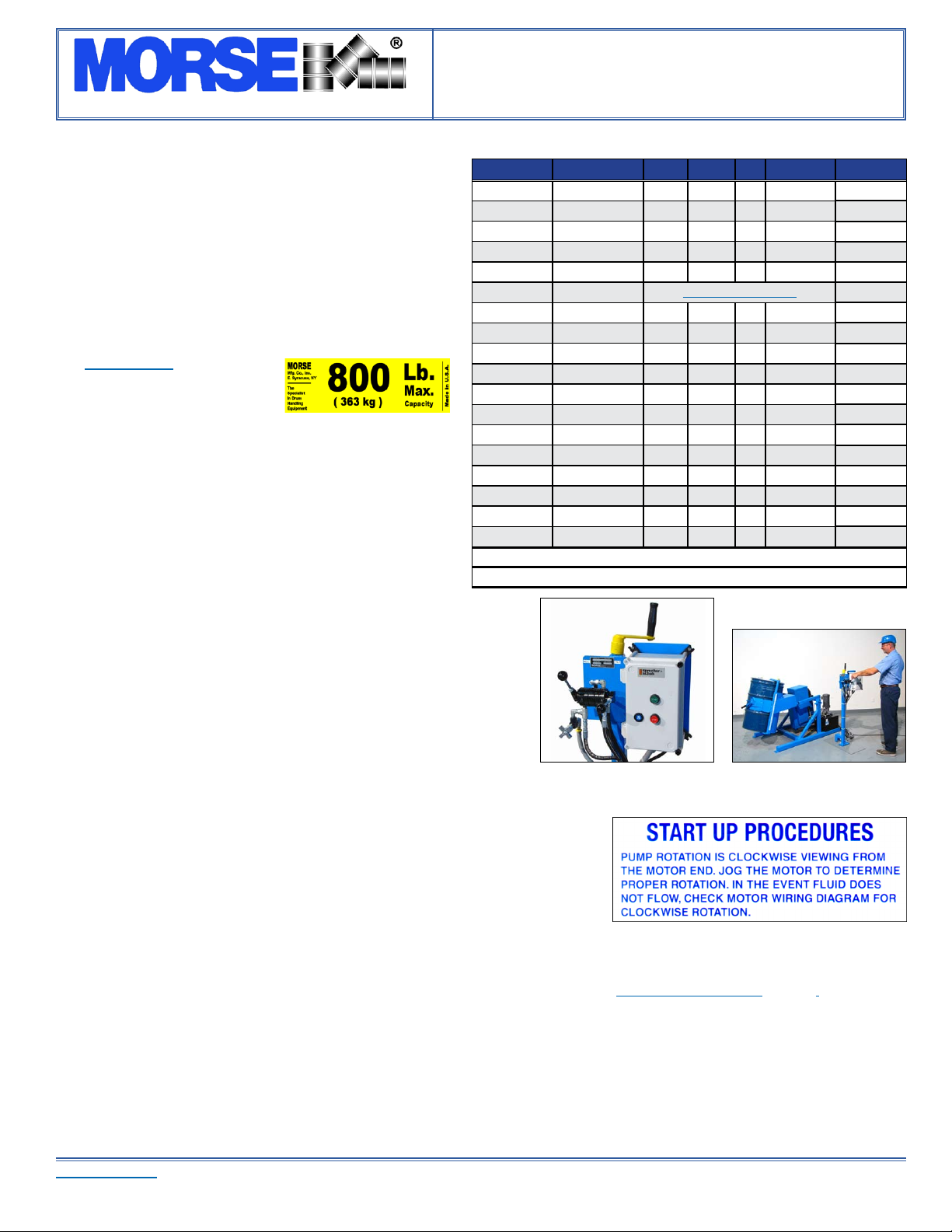
Model # Motor Style Phase Volts Hz Amp Draw Drum RPM
310-1-115 ** TEFC 1 115 60 23 5 to 20
310-1-230 TEFC 1 230 60 11.5 5 to 20
310-3-230 TEFC 3 230 60 5.8 5 to 20
310-3-460 TEFC 3 460 60 2.9 5 to 20
310-3-575 TEFC 3 575 60 2.2 5 to 20
310-A AirMotor AirMotorTechnicalInfo5 to 20
310-E1-115 Explosion Proof * 1 115 60 23 5 to 20
310-E1-230 Explosion Proof * 1 230 60 11.5 5 to 20
310-E3-230 Explosion Proof * 3 230 60 5.2 5 to 20
310-E3-460 Explosion Proof * 3 460 60 2.6 5 to 20
310-1-220-50 TEFC 1 220 50 9.7 4 to 16
310-3-220-50 TEFC 3 220 50 5.6 4 to 16
310-3-380-50 TEFC 3 380 50 3.2 4 to 16
310-3-440-50 TEFC 3 440 50 2.8 4 to 16
310-E1-220-50 Explosion Proof * 1 220 50 9.7 4 to 16
310-E3-220-50 Explosion Proof * 3 220 50 5.6 4 to 16
310-E3-380-50 Explosion Proof * 3 380 50 3.2 4 to 16
310-E3-440-50 Explosion Proof * 3 440 50 2.8 4 to 16
*ExplosionProofMotorsareratedforClassIGroupD,andClassIIGroupsFandG.
**Requires30Ampcircuit,andcanhavespikeshigherthanthat.
Control Station Man at Control Station